EP1580980B1 - Method and printing plate for adjusting exposure heads in an exposure unit for print data - Google Patents
Method and printing plate for adjusting exposure heads in an exposure unit for print data Download PDFInfo
- Publication number
- EP1580980B1 EP1580980B1 EP05100371A EP05100371A EP1580980B1 EP 1580980 B1 EP1580980 B1 EP 1580980B1 EP 05100371 A EP05100371 A EP 05100371A EP 05100371 A EP05100371 A EP 05100371A EP 1580980 B1 EP1580980 B1 EP 1580980B1
- Authority
- EP
- European Patent Office
- Prior art keywords
- test
- exposure
- recording
- fields
- area
- Prior art date
- Legal status (The legal status is an assumption and is not a legal conclusion. Google has not performed a legal analysis and makes no representation as to the accuracy of the status listed.)
- Expired - Lifetime
Links
- 238000007639 printing Methods 0.000 title claims description 48
- 238000000034 method Methods 0.000 title claims description 24
- 238000012360 testing method Methods 0.000 claims abstract description 113
- 239000000463 material Substances 0.000 claims description 27
- 238000012937 correction Methods 0.000 claims description 7
- 238000000926 separation method Methods 0.000 description 17
- 239000000976 ink Substances 0.000 description 10
- 238000011156 evaluation Methods 0.000 description 9
- 238000012216 screening Methods 0.000 description 7
- 229920000642 polymer Polymers 0.000 description 5
- 238000005259 measurement Methods 0.000 description 4
- 230000009467 reduction Effects 0.000 description 4
- 230000000007 visual effect Effects 0.000 description 4
- 239000003086 colorant Substances 0.000 description 3
- 238000001739 density measurement Methods 0.000 description 3
- 230000009471 action Effects 0.000 description 2
- 230000008859 change Effects 0.000 description 2
- 238000005516 engineering process Methods 0.000 description 2
- 230000012447 hatching Effects 0.000 description 2
- 230000003287 optical effect Effects 0.000 description 2
- 230000008569 process Effects 0.000 description 2
- 238000012545 processing Methods 0.000 description 2
- 238000005316 response function Methods 0.000 description 2
- 239000000758 substrate Substances 0.000 description 2
- 238000007651 thermal printing Methods 0.000 description 2
- PLXMOAALOJOTIY-FPTXNFDTSA-N Aesculin Natural products OC[C@@H]1[C@@H](O)[C@H](O)[C@@H](O)[C@H](O)[C@H]1Oc2cc3C=CC(=O)Oc3cc2O PLXMOAALOJOTIY-FPTXNFDTSA-N 0.000 description 1
- 241000393496 Electra Species 0.000 description 1
- 206010034972 Photosensitivity reaction Diseases 0.000 description 1
- 238000006243 chemical reaction Methods 0.000 description 1
- 238000010276 construction Methods 0.000 description 1
- 230000007423 decrease Effects 0.000 description 1
- 230000003247 decreasing effect Effects 0.000 description 1
- 230000002349 favourable effect Effects 0.000 description 1
- 238000003384 imaging method Methods 0.000 description 1
- 230000001788 irregular Effects 0.000 description 1
- 238000004519 manufacturing process Methods 0.000 description 1
- 239000011159 matrix material Substances 0.000 description 1
- 238000007649 pad printing Methods 0.000 description 1
- 230000036211 photosensitivity Effects 0.000 description 1
- 238000011002 quantification Methods 0.000 description 1
- 238000001226 reprecipitation Methods 0.000 description 1
- 238000012546 transfer Methods 0.000 description 1
- 230000007704 transition Effects 0.000 description 1
Images

Classifications
-
- H—ELECTRICITY
- H04—ELECTRIC COMMUNICATION TECHNIQUE
- H04N—PICTORIAL COMMUNICATION, e.g. TELEVISION
- H04N1/00—Scanning, transmission or reproduction of documents or the like, e.g. facsimile transmission; Details thereof
- H04N1/40—Picture signal circuits
- H04N1/407—Control or modification of tonal gradation or of extreme levels, e.g. background level
- H04N1/4076—Control or modification of tonal gradation or of extreme levels, e.g. background level dependent on references outside the picture
- H04N1/4078—Control or modification of tonal gradation or of extreme levels, e.g. background level dependent on references outside the picture using gradational references, e.g. grey-scale test pattern analysis
-
- G—PHYSICS
- G03—PHOTOGRAPHY; CINEMATOGRAPHY; ANALOGOUS TECHNIQUES USING WAVES OTHER THAN OPTICAL WAVES; ELECTROGRAPHY; HOLOGRAPHY
- G03G—ELECTROGRAPHY; ELECTROPHOTOGRAPHY; MAGNETOGRAPHY
- G03G15/00—Apparatus for electrographic processes using a charge pattern
- G03G15/04—Apparatus for electrographic processes using a charge pattern for exposing, i.e. imagewise exposure by optically projecting the original image on a photoconductive recording material
- G03G15/04036—Details of illuminating systems, e.g. lamps, reflectors
- G03G15/04045—Details of illuminating systems, e.g. lamps, reflectors for exposing image information provided otherwise than by directly projecting the original image onto the photoconductive recording material, e.g. digital copiers
- G03G15/04072—Details of illuminating systems, e.g. lamps, reflectors for exposing image information provided otherwise than by directly projecting the original image onto the photoconductive recording material, e.g. digital copiers by laser
-
- G—PHYSICS
- G03—PHOTOGRAPHY; CINEMATOGRAPHY; ANALOGOUS TECHNIQUES USING WAVES OTHER THAN OPTICAL WAVES; ELECTROGRAPHY; HOLOGRAPHY
- G03G—ELECTROGRAPHY; ELECTROPHOTOGRAPHY; MAGNETOGRAPHY
- G03G15/00—Apparatus for electrographic processes using a charge pattern
- G03G15/22—Apparatus for electrographic processes using a charge pattern involving the combination of more than one step according to groups G03G13/02 - G03G13/20
- G03G15/32—Apparatus for electrographic processes using a charge pattern involving the combination of more than one step according to groups G03G13/02 - G03G13/20 in which the charge pattern is formed dotwise, e.g. by a thermal head
- G03G15/326—Apparatus for electrographic processes using a charge pattern involving the combination of more than one step according to groups G03G13/02 - G03G13/20 in which the charge pattern is formed dotwise, e.g. by a thermal head by application of light, e.g. using a LED array
-
- H—ELECTRICITY
- H04—ELECTRIC COMMUNICATION TECHNIQUE
- H04N—PICTORIAL COMMUNICATION, e.g. TELEVISION
- H04N1/00—Scanning, transmission or reproduction of documents or the like, e.g. facsimile transmission; Details thereof
- H04N1/40—Picture signal circuits
- H04N1/401—Compensating positionally unequal response of the pick-up or reproducing head
- H04N1/4015—Compensating positionally unequal response of the pick-up or reproducing head of the reproducing head
-
- B—PERFORMING OPERATIONS; TRANSPORTING
- B41—PRINTING; LINING MACHINES; TYPEWRITERS; STAMPS
- B41C—PROCESSES FOR THE MANUFACTURE OR REPRODUCTION OF PRINTING SURFACES
- B41C1/00—Forme preparation
-
- B—PERFORMING OPERATIONS; TRANSPORTING
- B41—PRINTING; LINING MACHINES; TYPEWRITERS; STAMPS
- B41C—PROCESSES FOR THE MANUFACTURE OR REPRODUCTION OF PRINTING SURFACES
- B41C3/00—Reproduction or duplicating of printing formes
Definitions
- the invention relates to the field of electronic reproduction technology and relates to a method for aligning the exposure heads of an imagesetter, in particular an external drum imagesetter, which records artwork on printing plates. Furthermore, the invention relates to a test form for measuring and comparing the exposure intensities set in the exposure heads.
- print templates are created for printed pages containing all the elements to be printed, such as text, graphics and images.
- a separate print template is created for each ink, containing all the elements printed in each color.
- these are the inks cyan (C), magenta (M), yellow (Y), and black (K).
- C cyan
- M magenta
- Y yellow
- K black
- the printed originals separated by printing inks are also called color separations.
- the artwork is usually rasterized and exposed to a favorite on films, which then printing plates for high-volume printing produced.
- the print templates can be exposed directly on printing plates in special exposure devices or they are transferred directly as digital data to a digital printing press. There, the print data are then exposed to printing plates, for example, with an integrated into the printing unit exposure unit before immediately after the pad printing begins.
- the artwork is electronically reproduced. Images are scanned in a color scanner and stored in the form of digital data. Texts are created with word processing programs and graphics with drawing programs. With a layout program the image, text and graphic elements are combined to form a printed page. The data of several printed pages are combined with the data of further elements, such as registration marks, crop marks and folding marks as well as print control fields, to print templates for a printed sheet. After separation into the printing inks, the artworks are then in digital form. As data formats for describing the print templates, the page description languages Postscript and PDF (Portable Document Format) are widely used today.
- Postscript and PDF Portable Document Format
- the postscript or PDF data are converted before the recording of the print templates in a raster image processor (RIP) in a first step in color separation values for the color separations CMYK.
- RIP raster image processor
- the color separation values are a measure of the color densities with which the four printing colors cyan, magenta, yellow and black are printed on the substrate.
- spot colors In special cases where more than four colors are printed (spot colors), each pixel is described by as many color separation values as there are inks.
- the color separation values can be stored as data values with 8 bits per pixel and printing color, whereby the value range from 0% to 100% is subdivided into 256 tone value levels.
- Different tonal values of a color separation to be reproduced can only be reproduced in the print by a surface modulation of the applied printing inks, ie by screening.
- the area modulation of the printing inks can be carried out, for example, by a method for dot-screening in which the different tone levels of the color separation data are converted into screen dots of different sizes, which are arranged in a regular grid with periodically repeating grid cells.
- a raster cell for a typical 60 raster comprises a square with 1/60 cm edge length, ie a raster cell has the dimensions 166 ⁇ m ⁇ 166 ⁇ m.
- the halftone dots in the individual halftone cells are composed of exposure points which are an order of magnitude smaller than the halftone dots.
- a typical resolution of the exposure points is, for example, 1000 exposure points per centimeter, ie a Exposure point has the dimensions 10 microns ⁇ 10 microns.
- the artwork data of each color separation is described in the form of a high-resolution raster bit map containing one bit for each of the exposure points on the print area, indicating whether or not that exposure point is to be exposed.
- the tonal values are converted to a corresponding area coverage on the artwork, which is expressed as the tonal values in percent.
- the area coverage indicates what percentage of the area of a grid cell is exposed.
- an exposure beam is generated, for example a laser beam with a laser diode, formed by optical means and focused on the recording material and deflected by means of a deflection system point and line over the recording material.
- recording apparatuses which generate a bundle of laser beams to increase the exposure speed, for example with a separate laser light source for each laser beam, and simultaneously expose a plurality of recording lines of the printing form each time the recording material is scanned.
- the printing plates can be exposed to film material, so that so-called color separation films are formed, which subsequently serve by means of a photographic Umkopiervons for the production of printing plates.
- the printing plates themselves can be exposed in a platesetter or directly in a digital printing machine in which a unit for plate exposure is integrated.
- the recording material may be on a flat surface (flatbed imagesetter), in a cylindrical well (internal drum imagesetter) or on a drum (external drum imagesetter).
- Flatbed imagesetters operate predominantly with a fast rotating polygon mirror whose mirror surfaces direct the laser beam across the recording material while simultaneously moving the recording material perpendicular to the deflection direction of the laser beam. In this way, recording line for recording line is exposed. Since the length of the light path changes during the movement of the laser beam over the recording material, a complex imaging optics is required, which compensates for the resulting size changes of the exposure point.
- the material to be exposed is mounted on the inner surface of a partially open hollow cylinder and exposed to a laser beam directed along the cylinder axis onto a deflector which reflects the laser beam perpendicular to the material.
- the deflector a prism or a mirror, rotates at high speed during operation and is thereby moved in the direction of the cylinder axis, so that the deflected laser beam describes circular or helical recording lines on the material.
- the material to be exposed is mounted in the form of films or printing plates on a rotatably mounted drum.
- an exposure head is moved axially along the drum at a relatively short distance.
- the exposure head is moved in the feed direction by means of a feed screw with which it is positively connected and which is set in rotational motion by means of a feed drive.
- the exposure head focuses one or more laser beams onto the drum surface which sweep the drum surface in the form of helical lines. In this way, one or more recording lines are exposed to the recording material every drum revolution.
- external drum imagesetters preferably employ one or more exposure heads, each of which directs a bundle of N laser beams by means of an exposure optics as an axis of exposure of the exposure drum depict a linear array of exposure points on the surface of the recording material.
- the exposure heads are disposed on an exposure head carrier connected to the feed spindle so that all the exposure heads are moved together in the feed direction along the exposure drum by the rotational movement of the feed spindle.
- the exposure heads are spaced in the axial direction of the exposure drum at a distance that is a fraction of the axial drum length, for example three thirds of the axial drum length for three exposure heads.
- the exposure head carrier needs to be moved by means of the feed spindle only over a distance corresponding to the distance of the exposure heads.
- Each exposure head then exposes only one recording tape of the artwork.
- the recording time for the artwork is correspondingly short.
- the generated coverages must be equal within a narrow tolerance when the exposure heads are driven at the same tone value. Otherwise a disturbing leap in density occurs, for which the eye is particularly sensitive in a uniform area of the same tone value.
- the generated area coverage can be influenced within certain limits by changing the optical power of the laser beams in the exposure heads. In this way, the exposure heads can be matched to one another so that no density jump occurs during the transition from one recording band to the next.
- Such an alignment between two adjacent exposure heads could in principle be carried out with an iterative method in which the laser power of one exposure head remains unchanged and that of the other exposure head is changed stepwise. Each time, an area of the same tone is recorded and the record is visually assessed.
- EP-0529530-B1 A method for calibrating a multi-channel printer is described, which generates parallel laser beams with a plurality of laser diodes and focuses on a thermal recording material. With each laser diode, a test pattern is separately written, the laser diodes are driven with known tone values, and measured the density of the test pattern. From the comparison of the measured densities with the input tone values, corrected control values are calculated with which all laser diodes produce the same density value.
- the image outputs are pulsed laser diodes which are driven by a variable laser current and a variable pulse duration to produce different densities on a recording medium.
- a test pattern is exposed with several test fields of different nominal density, and then the recorded density of the test fields is measured.
- a response function is formed which records the recorded density in relation to the laser current and sets the pulse duration. Based on the difference between the measured densities and densities calculated after the response function, the drive values for the individual laser diodes are corrected, thereby reducing the recorded density variations between the laser diodes.
- Another object is to provide a test form with which the area coverage recorded by the individual exposure heads can be compared in a simple manner. The object is achieved by exposing one test form in each recording band associated with one exposure head and visually comparing the recorded arealities in contiguous recording bands. Without a density measurement, the test form allows the very precise quantification of the differences in the recorded area coverages, from which corresponding correction values for the laser powers in the exposure heads are derived. By means of the method according to the invention, the necessary correction values for all exposure heads can be determined simultaneously with a test exposure. Thus, the complete adjustment of the exposure heads can be achieved with only a few iterations.
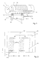
- Fig. 1 schematically shows the structure of an external drum imagesetter for exposing a printing original 15 on a recording material, in this example on a printing plate 3.
- An exposure drum 1 is rotatably mounted and can be offset with a rotary drive not shown in the direction of the rotation arrow 2 in a uniform rotational movement.
- an unexposed printing plate 3 is fixed by means of a clamping strip 9 at the front edge and by means of clamping pieces 10 at the trailing edge.
- the printing plate 3 is flat by means of a in Fig. 1 not shown, which sucks the pressure plate 3 through holes in the drum surface, held on the drum surface, so that the pressure plate 3 is not detached by the centrifugal forces in the rotation of the exposure drum 1.
- a plurality of exposure heads 11 arranged on a common exposure head carrier 16 are moved axially along the exposure drum 1 at a relatively short distance while the exposure drum 1 rotates.
- Each exposure head 11 focuses a bundle of exposure beams, in this example N laser beams 12, onto the drum surface, which sweep the drum surface in the form of helical lines.
- the exposure head carrier 16 is moved in the feed direction y (secondary scanning direction) by means of a feed screw 13, which is connected to the erformschiüssig and offset with a feed drive 14 in rotary motion becomes.
- the feed drive 14 is a stepper motor, wherein with the frequency of the motor supplied to the stepping motor clock, the feed rate can be accurately adjusted.
- the productivity of the imagesetter is increased, in particular for the exposure of large-format printing plates 3, since a printing plate 3 can be exposed in a shorter time.
- Fig. 1 There are two exposure heads 11, which are arranged in the feed direction at a distance W and each focus a bundle of N laser beams 12 on the pressure plate 3. The printing plate 3 is thereby exposed simultaneously with two groups of recording lines which cover the drum surface at an axial distance W.
- the distance W corresponds to half the maximum length that the imagesetter can record in the feed direction, one third of this maximum length in the case of three exposure heads 11, etc.
- the exposure head carrier 16 and thus all the exposure heads 11 have traveled the feed distance W, the exposure is Printing plate 3 regardless of the format of the recorded artwork 15 completed. The more exposure heads 11 are present, the shorter is the feed distance W and thus the exposure time, which is needed for recording.
- Fig. 2 illustrates the recording of the printing original 15, which results in the exposure with each N laser beams 12, on the unwound drum surface 20.
- the printing plate 3 is clamped, on which the printing original 15 is recorded.
- the recording takes place in each case in parallel with N laser beams 12, which are imaged as a feed direction oriented linear array of exposure points 21.
- Each exposure head 11 exposes Separate recording tape 23, each composed of the recording strip 22.
- the advancing speed of the exposure heads 11 is set to have moved in the advance direction by one drum revolution by the width of a recording tape 22, so that the recording stripes 22 exposed in each drum revolution seamlessly adjoin each other.
- the so-called interleave writing method the laser beams are not imaged as N exposure points spaced one record line at a time, but at a larger pitch which is a multiple of the width of a record line. With suitable combinations of line number N and line spacing, the gaps between the initially exposed recording lines are gradually filled with further recording lines in successive drum revolutions, so that finally a complete exposure of the recording material takes place.
- the last recording line of the first recording tape 23 adjoins the first recording line of the second recording tape 23 at the recording tape boundary 24.
- Visible jumps in density may occur at this boundary if the area coverage recorded by the neighboring exposure heads 11 at the same tone level does not coincide exactly.
- the eye is particularly sensitive, since even very small density changes can be perceived below 0.5%.
- the density jumps are caused by the fact that the exposure points 21 focused on the recording material by the laser beams 12 in the different exposure heads 11 may have slightly different diameters. These differences can be compensated by a corresponding adjustment of the laser power.
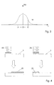
- the beam profile of a laser diode has the shape of a Gaussian bell curve as shown in FIG Fig. 3 is shown.
- the energy density H (r) has a maximum value in the middle of the beam and decreases with increasing radius r according to a Gaussian function.
- the print original is recorded on a so-called thermal printing plate, in which a polymer layer is imagewise destroyed and removed by the action of the laser energy.
- Such a printing plate is a positive-working printing plate, since the non-ink-bearing points are exposed imagewise.
- the term "positive” is derived from the comparison with the conventional reprecipitation of a positive color separation film on a printing plate, in which the printing plate is exposed through the transparent film areas, ie also at the non-ink-bearing points.
- Thermal printing plates which are exposed directly to a laser exhibit a threshold characteristic, ie the polymer layer is destroyed when the energy density H (r) exceeds a threshold value M and the polymer layer remains at a lower energy density ( Fig. 3 ). It follows immediately that the diameter D of the exposure points 21 can be increased as the laser energy is increased, and the diameter D of the exposure points 21 is reduced as the laser energy is reduced. Since it is a positive-working pressure plate, the area coverage of the ink-conducting areas changes inversely to the change in the diameter D, so that the area coverage is thus reduced by an increase in the laser energy and increased by a reduction of the laser energy.
- Fig. 4a schematically shows the position of the ink-carrying areas 25 of a positive pressure plate 3 relative to the exposed areas.
- Fig. 4b shows the same relation in a negative pressure plate.
- the correction values of the laser energy necessary for the adjustment of the exposure heads 11 are determined by simultaneously recording a special test form with all the exposure heads 11 after the laser energies of the laser beams 12 have first been set to a nominal operating point.
- a control device not explained here ensures that the N laser beams 12 within each exposure head 11 always emit the same laser energy once set.
- the laser units which generate the N laser beams 12 in each exposure head 11 as an array of exposure points 21 will also be referred to as a laser module.
- indications such as "changing the laser energy by ... mW" always refer to all laser beams 12 of a module, i. the energy of all laser beams is changed by the same amount.
- Fig. 5 shows the structure of the test form 50 according to the invention.
- the test form 50 is exposed in the feed direction y over the entire width W of a recording tape 23.
- the extent of the test mold 50 in the circumferential direction x is arbitrary.
- the test mold 50 includes a plurality of test pads 51 on a background surface 52.
- the background surface 52 is rasterized with a constant tone value, for example, with the tone value 70.0%. This tone value is particularly well suited for the visual assessment of the smallest density differences.
- One of the test fields 51 is rastered with the same tone as the background area 52, the remaining test fields 51 are rasterized with tone values, which in small steps both down and up from the tone value of the background area 52 differ, for example, in steps of 0.5%.
- test fields 51 is arbitrary, for example 21 test fields 51 in the tonal range of 65% to 75% can be provided.
- Fig. 5 For clarity, only seven test fields 51 are shown.
- the test fields 51 are arranged directly on the left edge of the test form 50, ie in the circumferential direction x of the recording.
- the nominal tonal values of the test fields 51 are indicated beside the test fields 51 by tonal values 53 which are also imprinted during the recording of the test form 50.
- a module designation 54 is also imprinted, which indicates with which laser module the test form 50 was recorded.
- the different screened tonal values of the test fields 51 and the background area 52 are in Fig. 5 characterized by differently dense hatching.
- the screening of the test fields 51 and the background area 52 can be carried out with an arbitrary screening method. Preferably, however, a frequency-modulated screening is used.
- Fig. 6 shows in high magnification examples with the tonal values 10% and 70%.
- the raster contains an irregular array of very small halftone dots, for example with a size of 20 ⁇ m, whose number increases with increasing tone value. Their size is not changed. With tonal values above 50%, more and more halftone dots touch each other, until finally, at high tonal values, a black area arises in which irregularly small "holes" are scattered.
- the frequency-modulated screening is more sensitive to changes in the laser power, ie the recorded area coverage changes more than in a conventional amplitude-modulated screening, in which regularly arranged halftone dots are varied in size. It is therefore better suited for the test form 50, which determines the setting values for the laser power in the exposure heads.
- the test mold 50 is recorded simultaneously with all the laser modules of the exposure heads 11.
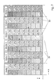
- Fig. 7 shows such a test exposure for an example in which six exposure heads 11 are present in an imagesetter and are to be matched.
- the test exposure thus contains six in Feed direction y juxtaposed test forms 50, which abut the recording tape boundaries 24 together. Since the laser powers are not yet balanced, the test forms 50 are recorded by the laser modules with a slightly different area coverage, which results in Fig. 7 again characterized by differently dense hatching.
- the test field 51 having the nominal 70.0% tone has the same areal coverage as the background area 52 of the same test form 50.
- the background area 52 of one test mold 50 and the test areas 51 of the adjacent one border Test form 50 directly to each other. This allows easy visual evaluation of the test exposure by comparing the module-exposed background area 52 to the test fields 51 exposed by the adjacent module. The visual comparison is more accurate than a density measurement that would have a measurement error of about 1% areal coverage. When compared visually differences in density of ⁇ 0.5% are still noticeable. In the test exposure, the test fields 51 exposed with the module 1 could also be omitted since they are not compared with any adjacent background area 52, ie for the module 1 it would be sufficient to expose only the background area 52.
- the test pattern 50 exposed to the module 2 has a somewhat larger areal coverage than the test pattern 50 exposed to the module 1, ie it is slightly darker overall. This is expressed by the fact that in the test form 50 of the module 2 the test field 51 with the nominal tone value 69.5% already reaches the same area coverage as the background area 52 in the test form 50 of the module 1 with the nominal tone value 70.0%. For a better overview, this match is in Fig. 7 marked with an arrow.
- the test form 50 of the module 3 is exposed overall somewhat brighter than the test form 50 of the module 2. Therefore, the area coverage of the background surface 52 of the module 2 is achieved by the module 3 only with the test field 51 with the nominal tone value 70.5%.
- the visual comparison is made at each recording tape boundary 24 between two modules, and the nominal ones Tone values of the test fields 51 whose area coverage coincides with the area coverage of the background of the preceding module or has the least difference are entered in the first line of an evaluation table.
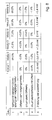
- Fig. 8 shows the evaluation table for the test exposure of Fig. 7
- the differences between the nominal tonal values of line 1 and the respective predecessor module are formed. These differences are then summed up by the module 1 beginning to the current module, and the sum is entered in a third line of the evaluation table.
- the values in line 3 thus indicate which area differences have the test forms 50 recorded with the respective modules with respect to the test form written with the module 1.
- correction values could already be calculated by which amounts the laser powers of the individual modules must be increased or decreased in order to align the exposure heads 11 with one another.
- the threshold value M is undershot, in which the polymer layer of the printing plate is reliably and completely removed ( Fig. 3 ), a common offset value is subtracted from the values in line 4 of the evaluation table so that no positive difference values occur.
- the offset values provided with the offset are entered in line 5 of the evaluation table. From these difference values, with the knowledge that, for example, an increase of the laser power by 3.6 mW causes a reduction of the area coverage by 1%, the power changes required for the adjustment can be calculated directly. These correction values are entered in line 5 of the evaluation table.
- test forms 50 In each case further test exposures are carried out with the corrected laser powers, the area coverages of background areas 52 and adjacent test areas 51 being compared again each time, and new correction values for the laser powers being calculated therefrom. After a few repetitions, typically after three iteration steps, the test forms 50 exposed with all the laser modules give the same area coverage, ie the adjustment of the Exposure heads 11 is completed. The accuracy of the adjustment can be further increased if, for the further iteration steps, a test form 50 is used in which the density levels between adjacent test fields 51 are chosen to be smaller, for example 0.25%.
- the process according to the invention was described using the example of a positive pressure plate. It can also be used for negative-working printing plates as well as for other recording materials, it being only necessary to pay attention to the direction in which the laser powers have to be changed in order, for example, to achieve a reduction of the area coverage or which threshold values or other limit values must be complied with. Also, the method and test form 50 are not limited to use in an external drum imagesetter, but they can be applied to any type of print original imagesetter that records a multiple exposure head artwork.
Landscapes
- Physics & Mathematics (AREA)
- Engineering & Computer Science (AREA)
- Multimedia (AREA)
- Signal Processing (AREA)
- General Physics & Mathematics (AREA)
- Optics & Photonics (AREA)
- Exposure And Positioning Against Photoresist Photosensitive Materials (AREA)
- Manufacture Or Reproduction Of Printing Formes (AREA)
- Accessory Devices And Overall Control Thereof (AREA)
- Facsimile Heads (AREA)
Abstract
Description
Die Erfindung bezieht sich auf das Gebiet der elektronischen Reproduktionstechnik und betrifft ein Verfahren zum Abgleichen der Belichtungsköpfe eines Belichters, insbesondere eines Außentrommelbelichters, der Druckvorlagen auf Druckplatten aufzeichnet. Weiterhin betrifft die Erfindung eine Testform zur Messung und zum Vergleich der in den Belichtungsköpfen eingestellten Belichtungsintensitäten.The invention relates to the field of electronic reproduction technology and relates to a method for aligning the exposure heads of an imagesetter, in particular an external drum imagesetter, which records artwork on printing plates. Furthermore, the invention relates to a test form for measuring and comparing the exposure intensities set in the exposure heads.
In der Reproduktionstechnik werden Druckvorlagen für Druckseiten erzeugt, die alle zu druckenden Elemente wie Texte, Grafiken und Bilder enthalten. Für den farbigen Druck wird für jede Druckfarbe eine separate Druckvorlage erzeugt, die alle Elemente enthält, die in der jeweiligen Farbe gedruckt werden. Für den Vierfarbdruck sind das die Druckfarben Cyan (C), Magenta (M), Gelb (Y) und Schwarz (K). Die nach Druckfarben separierten Druckvorlagen werden auch Farbauszüge genannt. Die Druckvorlagen werden in der Regel gerastert und mit einem Beliebter auf Filme belichtet, mit denen dann Druckplatten für das Drucken hoher Auflagen hergestellt werden. Alternativ können die Druckvorlagen in speziellen Belichtungsgeräten auch gleich auf Druckplatten belichtet werden oder sie werden direkt als digitale Daten an eine digitale Druckmaschine übergeben. Dort werden die Druckvorlagendaten dann beispielsweise mit einer in die Druckmaschine integrierten Belichtungseinheit auf Druckplatten belichtet, bevor unmittelbar anschließend der Auflagendruck beginnt.In reproduction technology, print templates are created for printed pages containing all the elements to be printed, such as text, graphics and images. For color printing, a separate print template is created for each ink, containing all the elements printed in each color. For four-color printing, these are the inks cyan (C), magenta (M), yellow (Y), and black (K). The printed originals separated by printing inks are also called color separations. The artwork is usually rasterized and exposed to a favorite on films, which then printing plates for high-volume printing produced. Alternatively, the print templates can be exposed directly on printing plates in special exposure devices or they are transferred directly as digital data to a digital printing press. There, the print data are then exposed to printing plates, for example, with an integrated into the printing unit exposure unit before immediately after the pad printing begins.
Nach dem heutigen Stand der Technik werden die Druckvorlagen elektronisch reproduziert. Dabei werden Bilder in einem Farbscanner gescannt und in Form von digitalen Daten gespeichert. Texte werden mit Textverarbeitungsprogrammen erzeugt und Grafiken mit Zeichenprogrammen. Mit einem Layoutprogramm werden die Bild-, Text- und Grafik-Elemente zu einer Druckseite zusammengestellt. Die Daten mehrerer Druckseiten werden mit den Daten weiterer Elemente, wie Passkreuzen, Schnittmarken und Falzmarken sowie Druckkontrollfeldern, zu Druckvorlagen für einen Druckbogen zusammengefasst. Nach der Separation in die Druckfarben liegen die Druckvorlagen dann in digitaler Form vor. Als Datenformate zur Beschreibung der Druckvorlagen werden heute weitgehend die Seitenbeschreibungssprachen Postscript und PDF (Portable Document Format) verwendet. Die Postscript- bzw. PDF-Daten werden vor der Aufzeichnung der Druckvorlagen in einem Raster-Image-Prozessor (RIP) in einem ersten Schritt in Farbauszugswerte für die Farbauszüge CMYK umgerechnet. Dabei entstehen für jeden Bildpunkt vier Farbauszugswerte als Tonwerte im Wertebereich von 0 bis 100%. Die Farbauszugswerte sind ein Maß für die Farbdichten, mit denen die vier Druckfarben Cyan, Magenta, Gelb und Schwarz auf dem Bedruckstoff gedruckt werden. In Sonderfällen, in denen mit mehr als vier Farben gedruckt wird (Schmuckfarben), ist jeder Bildpunkt durch so viele Farbauszugswerte beschrieben, wie es Druckfarben gibt. Die Farbauszugswerte können z.B. mit 8 bit je Bildpunkt und Druckfarbe als Datenwerte gespeichert sein, womit der Wertebereich von 0 % bis 100% in 256 Tonwertstufen unterteilt ist.According to the current state of the art, the artwork is electronically reproduced. Images are scanned in a color scanner and stored in the form of digital data. Texts are created with word processing programs and graphics with drawing programs. With a layout program the image, text and graphic elements are combined to form a printed page. The data of several printed pages are combined with the data of further elements, such as registration marks, crop marks and folding marks as well as print control fields, to print templates for a printed sheet. After separation into the printing inks, the artworks are then in digital form. As data formats for describing the print templates, the page description languages Postscript and PDF (Portable Document Format) are widely used today. The postscript or PDF data are converted before the recording of the print templates in a raster image processor (RIP) in a first step in color separation values for the color separations CMYK. This results in four color separation values for each pixel as tone values in the value range from 0 to 100%. The color separation values are a measure of the color densities with which the four printing colors cyan, magenta, yellow and black are printed on the substrate. In special cases where more than four colors are printed (spot colors), each pixel is described by as many color separation values as there are inks. For example, the color separation values can be stored as data values with 8 bits per pixel and printing color, whereby the value range from 0% to 100% is subdivided into 256 tone value levels.
Unterschiedliche Tonwerte eines zu reproduzierenden Farbauszugs lassen sich im Druck nur durch eine Flächenmodulation der aufgetragenen Druckfarben, d.h. durch eine Rasterung, wiedergeben. Die Flächenmodulation der Druckfarben kann beispielsweise nach einem Verfahren zur Punktrasterung erfolgen, bei dem die verschiedenen Tonwertstufen der Farbauszugsdaten in Rasterpunkte unterschiedlicher Größe umgewandelt werden, die in einem regelmäßigen Raster mit sich periodisch wiederholenden Rasterzellen angeordnet sind. Eine Rasterzelle für ein typisches 60er Raster umfasst ein Quadrat mit 1/60 cm Kantenlänge, d.h. eine Rasterzelle hat die Abmessungen 166 µm × 166 µm. Bei der Aufzeichnung der Farbauszüge auf eine Druckplatte werden die Rasterpunkte in den einzelnen Rasterzellen aus Belichtungspunkten zusammengesetzt, die um eine Größenordnung kleiner als die Rasterpunkte sind. Eine typische Auflösung der Belichtungspunkte ist beispielsweise 1000 Belichtungspunkte je Zentimeter, d.h. ein Belichtungspunkt hat die Abmessungen 10 µm × 10 µm. Die Umsetzung der Farbauszugswerte in Rasterpunkte geschieht in einem zweiten Schritt bei der weiteren Verarbeitung der Farbauszugsdaten im Raster-Image-Prozessor, wodurch die Farbauszugsdaten in hochaufgelöste Binärwerte mit nur zwei Helligkeitswerten (belichtet bzw. nicht belichtet) umgewandelt werden, die das Muster des modulierten Punktrasters bilden. Auf diese Weise werden die Druckvorlagendaten jedes Farbauszugs in Form einer hochaufgelösten Rasterbitmap beschrieben, die für jeden der Belichtungspunkte auf der Druckfläche ein Bit enthält, das angibt, ob dieser Belichtungspunkt zu belichten ist oder nicht. Die Tonwerte werden auf diese Weise in eine entsprechende Flächendeckung auf der Druckvorlage umgewandelt, die so wie die Tonwerte in Prozent angegeben wird. Die Flächendeckung gibt an, wie viel Prozent der Fläche einer Rasterzelle belichtet wird.Different tonal values of a color separation to be reproduced can only be reproduced in the print by a surface modulation of the applied printing inks, ie by screening. The area modulation of the printing inks can be carried out, for example, by a method for dot-screening in which the different tone levels of the color separation data are converted into screen dots of different sizes, which are arranged in a regular grid with periodically repeating grid cells. A raster cell for a typical 60 raster comprises a square with 1/60 cm edge length, ie a raster cell has the dimensions 166 μm × 166 μm. When recording the color separations on a printing plate, the halftone dots in the individual halftone cells are composed of exposure points which are an order of magnitude smaller than the halftone dots. A typical resolution of the exposure points is, for example, 1000 exposure points per centimeter, ie a Exposure point has the
In den Aufzeichnungsgeräten, die in der elektronischen Reproduktionstechnik zur Belichtung von Druckvorlagen eingesetzt werden, wird ein Belichtungsstrahl erzeugt, beispielsweise mit einer Laserdiode ein Laserstrahl, durch optische Mittel geformt und auf das Aufzeichnungsmaterial fokussiert und mittels eines Ablenksystems Punkt- und Linienweise über das Aufzeichnungsmaterial abgelenkt. Es gibt auch Aufzeichnungsgeräte, die zur Erhöhung der Belichtungsgeschwindigkeit ein Bündel von Laserstrahlen erzeugen, z.B. mit einer separaten Laserlichtquelle für jeden Laserstrahl, und mit jedem Überstreichen des Aufzeichnungsmaterials mehrere Aufzeichnungslinien der Druckform gleichzeitig belichten. Die Druckformen können auf Filmmaterial belichtet werden, so dass sogenannte Farbauszugsfilme entstehen, die anschließend mittels eines fotografischen Umkopierverfahrens zur Herstellung von Druckplatten dienen. Statt dessen können auch die Druckplatten selbst in einem Plattenbelichter oder direkt in einer digitalen Druckmaschine belichtet werden, in die eine Einheit zur Plattenbelichtung integriert ist. Das Aufzeichnungsmaterial kann sich auf einer ebenen Fläche befinden (Flachbettbelichter), in einer zylindrischen Mulde (Innentrommelbelichter) oder auf einer Trommel (Außentrommelbelichter).In the recording apparatuses used in the electronic reproduction technique for printing original documents, an exposure beam is generated, for example a laser beam with a laser diode, formed by optical means and focused on the recording material and deflected by means of a deflection system point and line over the recording material. There are also recording apparatuses which generate a bundle of laser beams to increase the exposure speed, for example with a separate laser light source for each laser beam, and simultaneously expose a plurality of recording lines of the printing form each time the recording material is scanned. The printing plates can be exposed to film material, so that so-called color separation films are formed, which subsequently serve by means of a photographic Umkopierverfahrens for the production of printing plates. Instead, the printing plates themselves can be exposed in a platesetter or directly in a digital printing machine in which a unit for plate exposure is integrated. The recording material may be on a flat surface (flatbed imagesetter), in a cylindrical well (internal drum imagesetter) or on a drum (external drum imagesetter).
Flachbettbelichter arbeiten überwiegend mit einem schnell rotierenden Polygonspiegel, dessen Spiegelflächen den Laserstrahl quer über das Aufzeichnungsmaterial lenken, während gleichzeitig das Aufzeichnungsmaterial senkrecht zur Ablenkrichtung des Laserstrahls bewegt wird. Auf diese Weise wird Aufzeichnungslinie für Aufzeichnungslinie belichtet. Da sich bei der Bewegung des Laserstrahls über das Aufzeichnungsmaterial die Länge des Lichtwegs ändert, ist eine aufwendige Abbildungsoptik erforderlich, die die dadurch bedingte Größenänderungen des Belichtungspunktes kompensiert.Flatbed imagesetters operate predominantly with a fast rotating polygon mirror whose mirror surfaces direct the laser beam across the recording material while simultaneously moving the recording material perpendicular to the deflection direction of the laser beam. In this way, recording line for recording line is exposed. Since the length of the light path changes during the movement of the laser beam over the recording material, a complex imaging optics is required, which compensates for the resulting size changes of the exposure point.
Bei einem Innentrommelbelichter wird das zu belichtende Material auf der Innenfläche eines teilweise offenen Hohlzylinders montiert und mit einem Laserstrahl belichtet, der entlang der Zylinderachse auf eine Ablenkvorrichtung gerichtet wird, die den Laserstrahl senkrecht auf das Material reflektiert. Die Ablenkvorrichtung, ein Prisma oder ein Spiegel, rotiert im Betrieb mit hoher Drehzahl und wird dabei in Richtung der Zylinderachse bewegt, so dass der abgelenkte Laserstrahl kreisförmige oder schraubenförmige Aufzeichnungslinien auf dem Material beschreibt.In an internal drum imagesetter, the material to be exposed is mounted on the inner surface of a partially open hollow cylinder and exposed to a laser beam directed along the cylinder axis onto a deflector which reflects the laser beam perpendicular to the material. The deflector, a prism or a mirror, rotates at high speed during operation and is thereby moved in the direction of the cylinder axis, so that the deflected laser beam describes circular or helical recording lines on the material.
Bei einem Außentrommelbelichter wird das zu belichtende Material in Form von Filmen oder Druckplatten auf eine drehbar gelagerte Trommel montiert. Während die Trommel rotiert, wird ein Belichtungskopf in einem relativ kurzen Abstand axial an der Trommel entlang bewegt. Der Belichtungskopf wird in der Vorschubrichtung mittels einer Vorschubspindel bewegt, mit der er formschlüssig verbunden ist und die mit einem Vorschubantrieb in Drehbewegung versetzt wird. Der Belichtungskopf fokussiert einen oder mehrere Laserstrahlen auf die Trommeloberfläche, die die Trommeloberfläche in Form von Schraubenlinien überstreichen. Auf diese Weise werden bei jeder Trommelumdrehung eine bzw. mehrere Aufzeichnungslinien auf das Aufzeichnungsmaterial belichtet.In an external drum imagesetter, the material to be exposed is mounted in the form of films or printing plates on a rotatably mounted drum. As the drum rotates, an exposure head is moved axially along the drum at a relatively short distance. The exposure head is moved in the feed direction by means of a feed screw with which it is positively connected and which is set in rotational motion by means of a feed drive. The exposure head focuses one or more laser beams onto the drum surface which sweep the drum surface in the form of helical lines. In this way, one or more recording lines are exposed to the recording material every drum revolution.
Um die Belichtungszeit zu verkürzen und damit die Wirtschaftlichkeit des Belichters zu erhöhen, arbeiten Außentrommelbelichter bevorzugt mit einem oder mehreren Belichtungsköpfen, die jeder ein Bündel von N Laserstrahlen mittels einer Belichtungsoptik als ein in Achsrichtung der Belichtungstrommel orientiertes lineares Array von Belichtungspunkten auf der Oberfläche des Aufzeichnungsmaterials abbilden. Wenn mehrere Belichtungsköpfe vorhanden sind, sind die Belichtungsköpfe beispielsweise auf einem Belichtungskopfträger angeordnet, der mit der Vorschubspindel verbunden ist, so dass durch die Drehbewegung der Vorschubspindel alle Belichtungsköpfe gemeinsam in Vorschubrichtung an der Belichtungstrommel entlang bewegt werden. Die Belichtungsköpfe sind in Achsrichtung der Belichtungstrommel in einem Abstand angeordnet, der ein Bruchteil der axialen Trommellänge ist, zum Beispiel bei drei Belichtungsköpfen ein Drittel der axialen Trommellänge. Um eine Druckvorlage über die gesamte Trommellänge aufzuzeichnen, braucht der Belichtungskopfträger mittels der Vorschubspindel nur über eine Strecke bewegt zu werden, die dem Abstand der Belichtungsköpfe entspricht. Jeder Belichtungskopf belichtet dann nur ein Aufzeichnungsband der Druckvorlage. Entsprechend kurz ist die Aufzeichnungszeit für die Druckvorlage.In order to shorten the exposure time and thus increase the economics of the imagesetter, external drum imagesetters preferably employ one or more exposure heads, each of which directs a bundle of N laser beams by means of an exposure optics as an axis of exposure of the exposure drum depict a linear array of exposure points on the surface of the recording material. For example, if there are multiple exposure heads, the exposure heads are disposed on an exposure head carrier connected to the feed spindle so that all the exposure heads are moved together in the feed direction along the exposure drum by the rotational movement of the feed spindle. The exposure heads are spaced in the axial direction of the exposure drum at a distance that is a fraction of the axial drum length, for example three thirds of the axial drum length for three exposure heads. To record a master copy over the entire length of the drum, the exposure head carrier needs to be moved by means of the feed spindle only over a distance corresponding to the distance of the exposure heads. Each exposure head then exposes only one recording tape of the artwork. The recording time for the artwork is correspondingly short.
An der Grenze zwischen den Aufzeichnungsbändern, die von den verschiedenen Belichtungsköpfen aufgezeichnet werden, müssen auch die erzeugten Flächendeckungen innerhalb einer engen Toleranz gleich sein, wenn die Belichtungsköpfe mit dem jeweils gleichen Tonwert angesteuert werden. Sonst entsteht ein störender Dichtesprung, für den das Auge in einer einheitlichen Fläche gleichen Tonwertes besonders empfindlich ist. Bei einem gleichbleibenden Tonwert kann die erzeugte Flächendeckung in bestimmten Grenzen durch die Veränderung der optischen Leistung der Laserstrahlen in den Belichtungsköpfen beeinflusst werden. Auf diese Weise können die Belichtungsköpfe so aufeinander abgeglichen werden, dass beim Übergang von einem Aufzeichnungsband zum nächsten kein Dichtesprung entsteht.Also, at the boundary between the recording tapes recorded by the different exposure heads, the generated coverages must be equal within a narrow tolerance when the exposure heads are driven at the same tone value. Otherwise a disturbing leap in density occurs, for which the eye is particularly sensitive in a uniform area of the same tone value. With a constant tone value, the generated area coverage can be influenced within certain limits by changing the optical power of the laser beams in the exposure heads. In this way, the exposure heads can be matched to one another so that no density jump occurs during the transition from one recording band to the next.
Ein solcher Abgleich zwischen zwei benachbarten Belichtungsköpfen könnte grundsätzlich mit einem iterativen Verfahren durchgeführt werden, bei dem die Laserleistung des einen Belichtungskopfes unverändert bleibt und die des anderen Belichtungskopfes schrittweise verändert wird. Jedes Mal wird eine Fläche mit dem gleichen Tonwert aufgezeichnet und die Aufzeichnung visuell beurteilt.Such an alignment between two adjacent exposure heads could in principle be carried out with an iterative method in which the laser power of one exposure head remains unchanged and that of the other exposure head is changed stepwise. Each time, an area of the same tone is recorded and the record is visually assessed.
Dies wird solange wiederholt, bis kein Dichtesprung mehr sichtbar ist. Dann wird in gleicher Weise der nächste Belichtungskopf abgeglichen, usw. Ein solches Verfahren wäre sehr zeitaufwendig, da die Belichtungsköpfe für jede Testbelichtung eine Vorschubstrecke durchlaufen müssen, die der Breite eines Aufzeichnungsbandes entspricht. Außerdem wäre der Verbrauch an Aufzeichnungsmaterial für die Testbelichtungen sehr hoch. Das iterative Verfahren kann durch eine zusätzliche Dichtemessung der aufgezeichneten Flächendeckungen beschleunigt werden. Wegen der Fähigkeit des Auges, auch sehr geringe Dichteänderungen unter 0,5% wahrzunehmen, und andererseits eines typischen Messfehlers von mehr als 1% reicht eine solchen Messung und eine daraus berechnete Änderung der Laserleistung allein für den optimalen Abgleich jedoch nicht aus. Die Messergebnisse können bestenfalls zum Auffinden günstiger Startwerte für die Iterationen herangezogen werden.This is repeated until no more density jump is visible. Then the next exposure head is adjusted in the same way, etc. Such a process would be very time consuming, since the exposure heads for each test exposure must pass through a feed distance corresponding to the width of a recording tape. In addition, the consumption of recording material for the test exposures would be very high. The iterative method can be accelerated by additional density measurement of the recorded areal coverage. However, due to the ability of the eye to perceive even very small density changes below 0.5%, and on the other hand a typical measurement error of more than 1%, such a measurement and a calculated change in laser power alone is not sufficient for the optimal alignment. At best, the measurement results can be used to find favorable starting values for the iterations.
In der
In der
Die bisher bekannten Verfahren zum Abgleichen der Belichtungsköpfe eines Belichters sind zeitaufwändig oder sie erreichen nicht die für die Anwendung in einem Druckvorlagenbelichter erforderliche hohe Genauigkeit.The previously known methods for aligning the exposure heads of an imagesetter are time consuming or they do not achieve the high accuracy required for use in a printing original imagesetter.
Es ist deshalb die Aufgabe der vorliegenden Erfindung, ein mit weniger Zeitaufwand arbeitendes sowie zuverlässiges und ausreichend genaues Verfahren zum Abgleichen der Belichtungsköpfe in einem Druckvorlagenbelichter anzugeben. Eine weitere Aufgabe ist es, eine Testform anzugeben, mit der die von den einzelnen Belichtungsköpfen aufgezeichneten Flächendeckungen in einfacher Weise verglichen werden können. Die Aufgabe wird gelöst, indem jeweils eine Testform in jedem Aufzeichnungsband, das einem Belichtungskopf zugeordnet ist, belichtet wird und die aufgezeichneten Flächendeckungen in aneinander grenzenden Aufzeichnungsbändern visuell verglichen werden. Die Testform ermöglicht ohne eine Dichtemessung die sehr genaue Quantifizierung der Unterschiede der aufgezeichneten Flächendeckungen, aus denen entsprechende Korrekturwerte für die Laserleistungen in den Belichtungsköpfen abgeleitet werden. Durch das erfindungsgemäße Verfahren können mit einer Testbelichtung die notwendigen Korrekturwerte für alle Belichtungsköpfe gleichzeitig festgestellt werden. Damit kann der vollständige Abgleich der Belichtungsköpfe mit nur wenigen Iterationsschritten erreicht werden.It is therefore the object of the present invention to provide a working with less time and reliable and sufficiently accurate method for adjusting the exposure heads in a Druckvorlagebelichter. Another object is to provide a test form with which the area coverage recorded by the individual exposure heads can be compared in a simple manner. The object is achieved by exposing one test form in each recording band associated with one exposure head and visually comparing the recorded arealities in contiguous recording bands. Without a density measurement, the test form allows the very precise quantification of the differences in the recorded area coverages, from which corresponding correction values for the laser powers in the exposure heads are derived. By means of the method according to the invention, the necessary correction values for all exposure heads can be determined simultaneously with a test exposure. Thus, the complete adjustment of the exposure heads can be achieved with only a few iterations.
Die Erfindung wird anhand der Figuren näher beschrieben.
Es zeigen:
- Fig. 1
- den Aufbau eines Außentrommelbelichters,
- Fig. 2
- die aufgezeichnete Druckvorlage auf einer abgewickelten Trommeloberfläche,
- Fig. 3
- das Strahlprofil eines Laserstrahls,
- Fig. 4
- die Wirkungsweise einer positiv arbeitenden und einer negativ arbeitenden Druckplatte,
- Fig. 5
- den Aufbau einer Testform,
- Fig. 6
- Beispiele für ein frequenzmoduliertes Raster,
- Fig. 7
- eine Testbelichtung mit mehreren Testformen,
und - Fig. 8
- eine Auswertungstabelle.
Show it:
- Fig. 1
- the construction of an external drum imagesetter,
- Fig. 2
- the recorded artwork on a unwound drum surface,
- Fig. 3
- the beam profile of a laser beam,
- Fig. 4
- the mode of action of a positive-working and a negative-working pressure plate,
- Fig. 5
- the structure of a test form,
- Fig. 6
- Examples of a frequency-modulated grid,
- Fig. 7
- a test exposure with several test forms,
and - Fig. 8
- an evaluation table.
Mehrere Belichtungsköpfe 11, die auf einem gemeinsamen Belichtungskopfträger 16 angeordnet sind, werden in einem relativ kurzen Abstand axial an der Belichtungstrommel 1 entlang bewegt, während die Belichtungstrommel 1 rotiert. Jeder Belichtungskopf 11 fokussiert ein Bündel von Belichtungsstrahlen, in diesem Beispiel N Laserstrahlen 12, auf die Trommeloberfläche, die die Trommeloberfläche in Form von Schraubenlinien überstreichen. Auf diese Weise werden bei jeder Trommelumdrehung eine bzw. mehrere Gruppen von N Aufzeichnungslinien in der Umfangsrichtung x (Hauptabtastrichtung) auf das Aufzeichnungsmaterial belichtet. Der Belichtungskopfträger 16 wird in der Vorschubrichtung y (Nebenabtastrichtung) mittels einer Vorschubspindel 13 bewegt, mit der erformschiüssig verbunden ist und die mit einem Vorschubantrieb 14 in Drehbewegung versetzt wird. Der Vorschubantrieb 14 ist ein Schrittmotor, wobei mit der Frequenz der dem Motor zugeführten Schrittmotortakte die Vorschubgeschwindigkeit genau eingestellt werden kann.A plurality of exposure heads 11 arranged on a common
Durch die Verwendung mehrerer Belichtungsköpfe 11 wird die Produktivität des Belichters erhöht, insbesondere für die Belichtung von großformatigen Druckplatten 3, da eine Druckplatte 3 in kürzerer Zeit belichtet werden kann. In dem Beispiel von
Am Ende des Vorschubwegs W schließt die letzte Aufzeichnungslinie des ersten Aufzeichnungsbandes 23 an die erste Aufzeichnungslinie des zweiten Aufzeichnungsbandes 23 an der Aufzeichnungsbandgrenze 24 an. An dieser Grenze kann es zu sichtbaren Dichtesprüngen kommen, wenn die bei gleichbleibendem Tonwert von den benachbarten Belichtungsköpfen 11 aufgezeichneten Flächendeckungen nicht exakt übereinstimmen. Für solche Dichtesprünge in einer einheitlichen Fläche gleichen Tonwertes ist das Auge besonders empfindlich, da auch sehr geringe Dichteänderungen unter 0,5% wahrgenommen werden können. Die Dichtesprünge werden dadurch verursacht, dass die von den Laserstrahlen 12 in den verschiedenen Belichtungsköpfen 11 auf das Aufzeichnungsmaterial fokussierten Belichtungspunkte 21 geringfügig unterschiedliche Durchmesser haben können. Diese Unterschiede können durch eine entsprechende Anpassung der Laserleistung ausgeglichen werden.At the end of the feed path W, the last recording line of the
Die Rasterpunkte werden bei der Belichtung der Druckvorlagen aus vielen kleinen Belichtungspunkten zusammengesetzt, z.B. mit einer Auflösung von 1000 Belichtungspunkten/cm. Um diese Auflösung zu erreichen, müssen die Aufzeichnungslinien einen Abstand a = 10 µm haben. Ob der Durchmesser der Belichtungspunkte ebenfalls auf D = 10µm eingestellt werden muss, hängt vom Strahlprofil des Laserstrahls und von den Belichtungseigenschaften des Aufzeichnungsmaterials ab. Das Strahlprofil einer Laserdiode hat die Form einer Gauß-Glockenkurve, wie sie in
Für die weitere Erläuterung eines Ausführungsbeispiels der Erfindung wird angenommen, dass die Druckvorlage auf eine sogenannte Thermal-Druckplatte aufgezeichnet wird, bei der eine Polymerschicht bildmäßig durch die Einwirkung der Laserenergie zerstört und abgetragen wird. Die verbleibenden Bereiche der Polymerschicht sind später in der Druckmaschine die farbführenden Bereiche, d.h. sie nehmen die Druckfarbe an und übertragen sie auf den Bedruckstoff. Eine solche Druckplatte ist eine positiv arbeitende Druckplatte, da die nicht farbführenden Stellen bildmäßig belichtet werden. Die Bezeichnung "positiv" wird aus dem Vergleich mit dem konventionellen Umkopieren eines positiven Farbauszugfilms auf eine Druckplatte abgeleitet, bei dem die Druckplatte durch die transparenten Filmbereiche hindurch belichtet wird, d.h. auch an den nicht farbführenden Stellen. Thermal-Druckplatten, die direkt mit einem Laser belichtet werden, weisen eine Schwellencharakteristik auf, d.h. die Polymerschicht wird zerstört, wenn die Energiedichte H(r) einen Schwellwert M überschreitet und die Polymerschicht bleibt bei einer geringeren Energiedichte erhalten (
Nach dem erfindungsgemäßen Verfahren werden die für den Abgleich der Belichtungsköpfe 11 notwendigen Korrekturwerte der Laserenergie ermittelt, indem mit allen Belichtungsköpfen 11 gleichzeitig eine besondere Testform aufgezeichnet wird, nachdem die Laserenergien der Laserstrahlen 12 zunächst auf einen nominellen Arbeitspunkt eingestellt wurden. Eine hier nicht erläuterte Regelungseinrichtung sorgt dafür, dass die N Laserstrahlen 12 innerhalb jedes Belichtungskopfes 11 stets die gleiche einmal eingestellte Laserenergie abstrahlen. Im folgenden werden die Lasereinheiten, die in jedem Belichtungskopf 11 die N Laserstrahlen 12 als Array von Belichtungspunkten 21 erzeugen, auch als Lasermodul bzw. Modul bezeichnet. Weiterhin beziehen sich Angaben wie "Veränderung der Laserenergie um ... mW" immer auf alle Laserstrahlen 12 eines Moduls, d.h. die Energie aller Laserstrahlen wird um den gleichen Betrag verändert.According to the method according to the invention, the correction values of the laser energy necessary for the adjustment of the exposure heads 11 are determined by simultaneously recording a special test form with all the exposure heads 11 after the laser energies of the
Die Rasterung der Testfelder 51 und der Hintergrundfläche 52 kann mit einem beliebigen Rasterverfahren erfolgen. Bevorzugt wird jedoch eine frequenzmodulierte Rasterung verwendet.
Die Testform 50 wird mit allen Lasermodulen der Belichtungsköpfe 11 gleichzeitig aufgezeichnet.
In dem Beispiel von
Das erfindungsgemäße Verfahren wurde am Beispiel einer positiv arbeitenden Druckplatte beschrieben. Es kann ebenso für negativ arbeitende Druckplatten sowie für andere Aufzeichnungsmaterialien verwendet werden, wobei nur zu beachten ist, in welche Richtung die Laserleistungen verändert werden müssen, um beispielsweise eine Verringerung der Flächendeckung zu bewirken, bzw. welche Schwellwerte oder andere Grenzwerte eingehalten werden müssen. Das Verfahren und die Testform 50 sind auch nicht auf die Anwendung in einem Außentrommelbelichter beschränkt, sondern sie können bei jeder Bauform eines Druckvorlagenbelichters eingesetzt werden, der eine Druckvorlage mit mehreren Belichtungsköpfen aufzeichnet.The process according to the invention was described using the example of a positive pressure plate. It can also be used for negative-working printing plates as well as for other recording materials, it being only necessary to pay attention to the direction in which the laser powers have to be changed in order, for example, to achieve a reduction of the area coverage or which threshold values or other limit values must be complied with. Also, the method and
Claims (10)
- Method of calibrating the exposure heads (11) of an exposure device including a number of exposure heads (11) for recording originals (15) on a recording material in terms of the recorded area coverage, wherein- every exposure head (11) includes a laser module that generates at least one laser beam (12) and focuses the laser beam onto the recording material,- the laser beams (12) scan the recording material in a main scanning direction (x) while the exposure heads (11) are moved along the recording material in a secondary scanning direction (y), and- wherein each exposure head (11) records a recording strip (23),characterized by
the facts that(a) a test exposure is made in which each exposure head (11) records a test form (50) including test fields (51) and a background area (52) in its recording strip (23)(b) the recorded area coverage of the background surface (52) is visually compared to the recorded area coverages of the test fields (51) in an adjacent test form (50),(c) the area coverages of those test fields (51) are determined that correspond to the area coverage of the background of the previous module or exhibit the lowest degree of deviation,(d) area coverage differences of adjacent test forms are determined by forming the differences of the determined area coverages relative to the respective previous module, and(e) that correcting values for the laser output of the laser modules in the exposure heads (11) are calculated from the differences of the area overages in adjacent test forms (50). - Method according to Claim 1, characterized by the fact that the test fields (51) of a test form (50) and the background area (52) of a neighbouring test form (50) are directly adjacent to each other.
- Method according to one of Claims 1 or 2, characterized by the fact that the test fields (51) and the background area (52) of a test form (60) are rastered with a frequency-modulated rastering.
- Method according to one of Claims 1 to 3, characterized by the fact that the background area (52) of a test form (50) is rastered with a first tonal value and the test fields (51) of the same test form (50) are rastered with tonal values that vary in small steps around the first tonal value.
- Method according to Claim 4, characterized by the fact that the first tonal value amounts to 70.0% and the tonal values of the test fields (51) vary in steps of 0.5% in a range from 65% to 75%.
- Method according to one of Claims 1 to 4, characterized by the fact that the test exposure and the correction of the laser output are iteratively repeated until the recorded area coverages are the same in all test forms (50) of a test exposure.
- Method according to Claim 6, characterized by the fact that for the further iterations of the test exposure, a test form (50) is used in which the tonal value steps between the test fields (51) are selected to be smaller than for the first test exposures.
- Printing plate including several test forms (50) that are exposed in accordance with an original (15) to be used in calibrating exposure heads (11) of an exposure device that records an original (15) on a recording material in adjacent recording strips (23) of multiple exposure heads (11) in terms of the recorded area coverage,
characterized by
the fact that each test form includes a background area (52) that is rastered with a first tonal value and several test fields (51) that are rastered with tonal values that vary in small steps about the first tonal value, the test fields (51) being arranged at an edge of the test form (50) that extends in the main scanning direction (x) and corresponds to the recording strip border (24) of two exposure heads (11), the test fields in the secondary scanning direction (y) being smaller than the width of the test form (50) in the secondary scanning direction so that the background area (52) of a test form (50) and the test fields (51) of the adjacent test form (50) are directly adjacent to each other. - Test form (50) according to Claim 8, characterized by the fact that the first tonal value is 70.0% and the tonal values of the test fields vary in steps of 0.5% in a range from 65% to 75%.
- Test form (50) according to one of Claims 8 or 9, characterized by the fact that the test field (51) and the background area (52) are rastered with a frequency-modulated rastering.
Applications Claiming Priority (2)
| Application Number | Priority Date | Filing Date | Title |
|---|---|---|---|
| DE102004008074 | 2004-02-19 | ||
| DE102004008074A DE102004008074A1 (en) | 2004-02-19 | 2004-02-19 | Method and test form for adjusting the exposure heads in an imagesetter for printing originals |
Publications (3)
| Publication Number | Publication Date |
|---|---|
| EP1580980A2 EP1580980A2 (en) | 2005-09-28 |
| EP1580980A3 EP1580980A3 (en) | 2010-01-20 |
| EP1580980B1 true EP1580980B1 (en) | 2011-12-28 |
Family
ID=34853522
Family Applications (1)
| Application Number | Title | Priority Date | Filing Date |
|---|---|---|---|
| EP05100371A Expired - Lifetime EP1580980B1 (en) | 2004-02-19 | 2005-01-21 | Method and printing plate for adjusting exposure heads in an exposure unit for print data |
Country Status (5)
| Country | Link |
|---|---|
| US (1) | US7289137B2 (en) |
| EP (1) | EP1580980B1 (en) |
| JP (1) | JP4215730B2 (en) |
| AT (1) | ATE539550T1 (en) |
| DE (1) | DE102004008074A1 (en) |
Families Citing this family (7)
| Publication number | Priority date | Publication date | Assignee | Title |
|---|---|---|---|---|
| JP4558464B2 (en) * | 2004-11-30 | 2010-10-06 | 株式会社リコー | Image forming apparatus and image forming method |
| JP4938783B2 (en) * | 2005-10-26 | 2012-05-23 | マイクロニック レーザー システムズ アクチボラゲット | Writing apparatus and writing method |
| US8122846B2 (en) * | 2005-10-26 | 2012-02-28 | Micronic Mydata AB | Platforms, apparatuses, systems and methods for processing and analyzing substrates |
| EP2972589B1 (en) | 2013-03-12 | 2017-05-03 | Micronic Mydata AB | Mechanically produced alignment fiducial method and alignment system |
| WO2014140047A2 (en) | 2013-03-12 | 2014-09-18 | Micronic Mydata AB | Method and device for writing photomasks with reduced mura errors |
| CN108353111B (en) | 2015-10-30 | 2020-03-17 | 惠普发展公司有限责任合伙企业 | Print inconsistency quantification |
| US11169463B2 (en) * | 2017-08-25 | 2021-11-09 | Hp Indigo B.V. | Adjusting power levels to compensate for print spot size variation |
Family Cites Families (16)
| Publication number | Priority date | Publication date | Assignee | Title |
|---|---|---|---|---|
| US5323179A (en) * | 1991-08-23 | 1994-06-21 | Eastman Kodak Company | Method of calibrating a multichannel printer |
| US5598272A (en) * | 1994-04-07 | 1997-01-28 | Imation, Inc. | Visual calibrator for color halftone imaging |
| US5638117A (en) | 1994-11-14 | 1997-06-10 | Sonnetech, Ltd. | Interactive method and system for color characterization and calibration of display device |
| US6034711A (en) * | 1996-03-06 | 2000-03-07 | Hewlett-Packard Company | Self-indicating test page for use in setting density level and color balance in a color laser printer |
| US5838117A (en) * | 1997-02-28 | 1998-11-17 | General Electric Company | Ballast circuit with synchronization and preheat functions |
| US6128090A (en) * | 1996-12-11 | 2000-10-03 | Agfa Gevaert N.V. | Visual control strip for imageable media |
| US6721061B1 (en) * | 1997-02-13 | 2004-04-13 | Agfa Corporation | Method and apparatus for display of banding |
| US5933578A (en) * | 1997-04-08 | 1999-08-03 | Barco Graphics, N.V. | Method and device for determining the color appearance of color overprints |
| WO1999023605A1 (en) * | 1997-11-03 | 1999-05-14 | Imation Corp. | Method and device for calibrating an imaging apparatus having multiple imaging outputs |
| US6268932B1 (en) * | 1998-04-23 | 2001-07-31 | Internatiaonal Business Machines Corporation | Gray scale calibration tool for setting the density of a printer |
| US6215562B1 (en) * | 1998-12-16 | 2001-04-10 | Electronics For Imaging, Inc. | Visual calibration |
| EP1199881A1 (en) * | 2000-10-18 | 2002-04-24 | Ricoh Company, Ltd. | Image forming apparatus adjusting concentration of gray with improved reference and test patterns |
| US6832552B2 (en) * | 2001-06-26 | 2004-12-21 | Creo Inc. | Method of automated setting of imaging and processing parameters |
| US7034968B2 (en) * | 2001-08-31 | 2006-04-25 | Hewlett-Packard Development Company, L.P. | Color calibration chart |
| JP3820979B2 (en) * | 2001-12-17 | 2006-09-13 | ブラザー工業株式会社 | Patch forming apparatus and program |
| AP2004003112A0 (en) | 2002-02-14 | 2004-09-30 | Ranbaxy Lab Ltd | Formulations of atorvastatin stabilised with alkali metal additions |
-
2004
- 2004-02-19 DE DE102004008074A patent/DE102004008074A1/en not_active Withdrawn
-
2005
- 2005-01-21 EP EP05100371A patent/EP1580980B1/en not_active Expired - Lifetime
- 2005-01-21 AT AT05100371T patent/ATE539550T1/en active
- 2005-02-21 JP JP2005044747A patent/JP4215730B2/en not_active Expired - Fee Related
- 2005-02-22 US US11/062,998 patent/US7289137B2/en not_active Expired - Fee Related
Also Published As
| Publication number | Publication date |
|---|---|
| US7289137B2 (en) | 2007-10-30 |
| DE102004008074A1 (en) | 2005-09-15 |
| JP2005234586A (en) | 2005-09-02 |
| ATE539550T1 (en) | 2012-01-15 |
| JP4215730B2 (en) | 2009-01-28 |
| EP1580980A3 (en) | 2010-01-20 |
| US20050185161A1 (en) | 2005-08-25 |
| EP1580980A2 (en) | 2005-09-28 |
Similar Documents
| Publication | Publication Date | Title |
|---|---|---|
| DE2262824C3 (en) | Process for the rasterized reproduction of colored halftone images in single or multi-color printing | |
| DE2809338C3 (en) | Density control arrangement for inkjet printers | |
| DE60119612T2 (en) | More ray exposure device | |
| DE10306104B4 (en) | Apparatus and method for detecting the edge of a recording material | |
| DE2720782A1 (en) | ELECTRONIC HALFTONE GENERATOR | |
| EP0074422A1 (en) | Method for the production of printing plates by means of printing irregularly distributed points | |
| EP0719434B1 (en) | Arrangement for generating a matrix image on a photosensitive recording medium | |
| WO1981000466A1 (en) | Autotypical analysis process of toning values | |
| EP1580980B1 (en) | Method and printing plate for adjusting exposure heads in an exposure unit for print data | |
| DE10353029B3 (en) | Displacement spindle length variation measuring method, for printing plate exposure device, uses measurement of stepping motor clock pulses for displacement of exposure head carrier along reference path | |
| EP1530151B1 (en) | Process for correcting the recording skew when illuminating a printing master | |
| DE69326646T2 (en) | Method and device for improving resolution and contrast through oversampled illumination with intensity control in a two-dimensional micro-addressable printer | |
| EP1450210B1 (en) | Apparatus and method for detecting the edge of a recording material | |
| DE69714197T2 (en) | Visible control strip for imaging media | |
| DE4007716C2 (en) | ||
| DE2219442A1 (en) | Image transmission device, in particular facsimile writer | |
| EP2177356B1 (en) | Compensation of errors in an imaging device | |
| DE4303081C2 (en) | Method and device for exposure calibration of recording devices | |
| DE3010880C2 (en) | Raster conversion process for engraving printing forms | |
| DE3046397C2 (en) | Digital photo typesetting machine | |
| EP0029561A1 (en) | Method and device for arriving at desired values, especially for the automatic presetting of printing machines | |
| DE69617200T2 (en) | Halftone reproduction by recording individual points using several laser beams | |
| DE3615126C2 (en) | ||
| EP1832924B1 (en) | Process sensitometric strip and recording method | |
| EP0753960B1 (en) | Method for producing grey-scale designs |
Legal Events
| Date | Code | Title | Description |
|---|---|---|---|
| PUAI | Public reference made under article 153(3) epc to a published international application that has entered the european phase |
Free format text: ORIGINAL CODE: 0009012 |
|
| AK | Designated contracting states |
Kind code of ref document: A2 Designated state(s): AT BE BG CH CY CZ DE DK EE ES FI FR GB GR HU IE IS IT LI LT LU MC NL PL PT RO SE SI SK TR |
|
| AX | Request for extension of the european patent |
Extension state: AL BA HR LV MK YU |
|
| PUAL | Search report despatched |
Free format text: ORIGINAL CODE: 0009013 |
|
| AK | Designated contracting states |
Kind code of ref document: A3 Designated state(s): AT BE BG CH CY CZ DE DK EE ES FI FR GB GR HU IE IS IT LI LT LU MC NL PL PT RO SE SI SK TR |
|
| AX | Request for extension of the european patent |
Extension state: AL BA HR LV MK YU |
|
| RIC1 | Information provided on ipc code assigned before grant |
Ipc: H04N 1/407 20060101ALI20091214BHEP Ipc: H04N 1/401 20060101AFI20050729BHEP |
|
| 17P | Request for examination filed |
Effective date: 20100720 |
|
| 17Q | First examination report despatched |
Effective date: 20100813 |
|
| AKX | Designation fees paid |
Designated state(s): AT BE BG CH CY CZ DE DK EE ES FI FR GB GR HU IE IS IT LI LT LU MC NL PL PT RO SE SI SK TR |
|
| GRAP | Despatch of communication of intention to grant a patent |
Free format text: ORIGINAL CODE: EPIDOSNIGR1 |
|
| RTI1 | Title (correction) |
Free format text: METHOD AND PRINTING PLATE FOR ADJUSTING EXPOSURE HEADS IN AN EXPOSURE UNIT FOR PRINT DATA |
|
| RIN1 | Information on inventor provided before grant (corrected) |
Inventor name: LIEBIG, NORBERTC/O HEIDELBERGER DRUCKMASCHINEN |
|
| GRAS | Grant fee paid |
Free format text: ORIGINAL CODE: EPIDOSNIGR3 |
|
| GRAA | (expected) grant |
Free format text: ORIGINAL CODE: 0009210 |
|
| AK | Designated contracting states |
Kind code of ref document: B1 Designated state(s): AT BE BG CH CY CZ DE DK EE ES FI FR GB GR HU IE IS IT LI LT LU MC NL PL PT RO SE SI SK TR |
|
| REG | Reference to a national code |
Ref country code: GB Ref legal event code: FG4D Free format text: NOT ENGLISH |
|
| REG | Reference to a national code |
Ref country code: CH Ref legal event code: EP |
|
| REG | Reference to a national code |
Ref country code: AT Ref legal event code: REF Ref document number: 539550 Country of ref document: AT Kind code of ref document: T Effective date: 20120115 |
|
| REG | Reference to a national code |
Ref country code: IE Ref legal event code: FG4D |
|
| REG | Reference to a national code |
Ref country code: NL Ref legal event code: T3 |
|
| REG | Reference to a national code |
Ref country code: DE Ref legal event code: R096 Ref document number: 502005012265 Country of ref document: DE Effective date: 20120322 |
|
| PG25 | Lapsed in a contracting state [announced via postgrant information from national office to epo] |
Ref country code: LT Free format text: LAPSE BECAUSE OF FAILURE TO SUBMIT A TRANSLATION OF THE DESCRIPTION OR TO PAY THE FEE WITHIN THE PRESCRIBED TIME-LIMIT Effective date: 20111228 |
|
| LTIE | Lt: invalidation of european patent or patent extension |
Effective date: 20111228 |
|
| PG25 | Lapsed in a contracting state [announced via postgrant information from national office to epo] |
Ref country code: GR Free format text: LAPSE BECAUSE OF FAILURE TO SUBMIT A TRANSLATION OF THE DESCRIPTION OR TO PAY THE FEE WITHIN THE PRESCRIBED TIME-LIMIT Effective date: 20120329 Ref country code: SI Free format text: LAPSE BECAUSE OF FAILURE TO SUBMIT A TRANSLATION OF THE DESCRIPTION OR TO PAY THE FEE WITHIN THE PRESCRIBED TIME-LIMIT Effective date: 20111228 Ref country code: SE Free format text: LAPSE BECAUSE OF FAILURE TO SUBMIT A TRANSLATION OF THE DESCRIPTION OR TO PAY THE FEE WITHIN THE PRESCRIBED TIME-LIMIT Effective date: 20111228 |
|
| PG25 | Lapsed in a contracting state [announced via postgrant information from national office to epo] |
Ref country code: CY Free format text: LAPSE BECAUSE OF FAILURE TO SUBMIT A TRANSLATION OF THE DESCRIPTION OR TO PAY THE FEE WITHIN THE PRESCRIBED TIME-LIMIT Effective date: 20111228 |
|
| REG | Reference to a national code |
Ref country code: IE Ref legal event code: FD4D |
|
| BERE | Be: lapsed |
Owner name: HEIDELBERGER DRUCKMASCHINEN A.G. Effective date: 20120131 |
|
| PG25 | Lapsed in a contracting state [announced via postgrant information from national office to epo] |
Ref country code: EE Free format text: LAPSE BECAUSE OF FAILURE TO SUBMIT A TRANSLATION OF THE DESCRIPTION OR TO PAY THE FEE WITHIN THE PRESCRIBED TIME-LIMIT Effective date: 20111228 Ref country code: IE Free format text: LAPSE BECAUSE OF FAILURE TO SUBMIT A TRANSLATION OF THE DESCRIPTION OR TO PAY THE FEE WITHIN THE PRESCRIBED TIME-LIMIT Effective date: 20111228 Ref country code: IS Free format text: LAPSE BECAUSE OF FAILURE TO SUBMIT A TRANSLATION OF THE DESCRIPTION OR TO PAY THE FEE WITHIN THE PRESCRIBED TIME-LIMIT Effective date: 20120428 Ref country code: SK Free format text: LAPSE BECAUSE OF FAILURE TO SUBMIT A TRANSLATION OF THE DESCRIPTION OR TO PAY THE FEE WITHIN THE PRESCRIBED TIME-LIMIT Effective date: 20111228 Ref country code: BG Free format text: LAPSE BECAUSE OF FAILURE TO SUBMIT A TRANSLATION OF THE DESCRIPTION OR TO PAY THE FEE WITHIN THE PRESCRIBED TIME-LIMIT Effective date: 20120328 Ref country code: CZ Free format text: LAPSE BECAUSE OF FAILURE TO SUBMIT A TRANSLATION OF THE DESCRIPTION OR TO PAY THE FEE WITHIN THE PRESCRIBED TIME-LIMIT Effective date: 20111228 |
|
| PG25 | Lapsed in a contracting state [announced via postgrant information from national office to epo] |
Ref country code: RO Free format text: LAPSE BECAUSE OF FAILURE TO SUBMIT A TRANSLATION OF THE DESCRIPTION OR TO PAY THE FEE WITHIN THE PRESCRIBED TIME-LIMIT Effective date: 20111228 Ref country code: PT Free format text: LAPSE BECAUSE OF FAILURE TO SUBMIT A TRANSLATION OF THE DESCRIPTION OR TO PAY THE FEE WITHIN THE PRESCRIBED TIME-LIMIT Effective date: 20120430 Ref country code: MC Free format text: LAPSE BECAUSE OF NON-PAYMENT OF DUE FEES Effective date: 20120131 Ref country code: PL Free format text: LAPSE BECAUSE OF FAILURE TO SUBMIT A TRANSLATION OF THE DESCRIPTION OR TO PAY THE FEE WITHIN THE PRESCRIBED TIME-LIMIT Effective date: 20111228 |
|
| REG | Reference to a national code |
Ref country code: CH Ref legal event code: PL |
|
| PGFP | Annual fee paid to national office [announced via postgrant information from national office to epo] |
Ref country code: IT Payment date: 20120127 Year of fee payment: 8 |
|
| PG25 | Lapsed in a contracting state [announced via postgrant information from national office to epo] |
Ref country code: DK Free format text: LAPSE BECAUSE OF FAILURE TO SUBMIT A TRANSLATION OF THE DESCRIPTION OR TO PAY THE FEE WITHIN THE PRESCRIBED TIME-LIMIT Effective date: 20111228 Ref country code: LI Free format text: LAPSE BECAUSE OF NON-PAYMENT OF DUE FEES Effective date: 20120131 Ref country code: CH Free format text: LAPSE BECAUSE OF NON-PAYMENT OF DUE FEES Effective date: 20120131 |
|
| PLBE | No opposition filed within time limit |
Free format text: ORIGINAL CODE: 0009261 |
|
| STAA | Information on the status of an ep patent application or granted ep patent |
Free format text: STATUS: NO OPPOSITION FILED WITHIN TIME LIMIT |
|
| 26N | No opposition filed |
Effective date: 20121001 |
|
| PG25 | Lapsed in a contracting state [announced via postgrant information from national office to epo] |
Ref country code: BE Free format text: LAPSE BECAUSE OF NON-PAYMENT OF DUE FEES Effective date: 20120131 |
|
| REG | Reference to a national code |
Ref country code: DE Ref legal event code: R097 Ref document number: 502005012265 Country of ref document: DE Effective date: 20121001 |
|
| REG | Reference to a national code |
Ref country code: AT Ref legal event code: MM01 Ref document number: 539550 Country of ref document: AT Kind code of ref document: T Effective date: 20120121 |
|
| PG25 | Lapsed in a contracting state [announced via postgrant information from national office to epo] |
Ref country code: ES Free format text: LAPSE BECAUSE OF FAILURE TO SUBMIT A TRANSLATION OF THE DESCRIPTION OR TO PAY THE FEE WITHIN THE PRESCRIBED TIME-LIMIT Effective date: 20120408 |
|
| PGFP | Annual fee paid to national office [announced via postgrant information from national office to epo] |
Ref country code: NL Payment date: 20130121 Year of fee payment: 9 |
|
| PG25 | Lapsed in a contracting state [announced via postgrant information from national office to epo] |
Ref country code: FI Free format text: LAPSE BECAUSE OF FAILURE TO SUBMIT A TRANSLATION OF THE DESCRIPTION OR TO PAY THE FEE WITHIN THE PRESCRIBED TIME-LIMIT Effective date: 20111228 Ref country code: AT Free format text: LAPSE BECAUSE OF NON-PAYMENT OF DUE FEES Effective date: 20120121 |
|
| PG25 | Lapsed in a contracting state [announced via postgrant information from national office to epo] |
Ref country code: TR Free format text: LAPSE BECAUSE OF FAILURE TO SUBMIT A TRANSLATION OF THE DESCRIPTION OR TO PAY THE FEE WITHIN THE PRESCRIBED TIME-LIMIT Effective date: 20111228 |
|
| PG25 | Lapsed in a contracting state [announced via postgrant information from national office to epo] |
Ref country code: LU Free format text: LAPSE BECAUSE OF NON-PAYMENT OF DUE FEES Effective date: 20120121 |
|
| PG25 | Lapsed in a contracting state [announced via postgrant information from national office to epo] |
Ref country code: HU Free format text: LAPSE BECAUSE OF FAILURE TO SUBMIT A TRANSLATION OF THE DESCRIPTION OR TO PAY THE FEE WITHIN THE PRESCRIBED TIME-LIMIT Effective date: 20050121 |
|
| REG | Reference to a national code |
Ref country code: NL Ref legal event code: V1 Effective date: 20140801 |
|
| PG25 | Lapsed in a contracting state [announced via postgrant information from national office to epo] |
Ref country code: NL Free format text: LAPSE BECAUSE OF NON-PAYMENT OF DUE FEES Effective date: 20140801 |
|
| REG | Reference to a national code |
Ref country code: FR Ref legal event code: PLFP Year of fee payment: 11 |
|
| PGFP | Annual fee paid to national office [announced via postgrant information from national office to epo] |
Ref country code: DE Payment date: 20150131 Year of fee payment: 11 |
|
| PGFP | Annual fee paid to national office [announced via postgrant information from national office to epo] |
Ref country code: FR Payment date: 20150119 Year of fee payment: 11 Ref country code: GB Payment date: 20150122 Year of fee payment: 11 |
|
| PG25 | Lapsed in a contracting state [announced via postgrant information from national office to epo] |
Ref country code: IT Free format text: LAPSE BECAUSE OF NON-PAYMENT OF DUE FEES Effective date: 20140121 |
|
| REG | Reference to a national code |
Ref country code: DE Ref legal event code: R119 Ref document number: 502005012265 Country of ref document: DE |
|
| GBPC | Gb: european patent ceased through non-payment of renewal fee |
Effective date: 20160121 |
|
| REG | Reference to a national code |
Ref country code: FR Ref legal event code: ST Effective date: 20160930 |
|
| PG25 | Lapsed in a contracting state [announced via postgrant information from national office to epo] |
Ref country code: GB Free format text: LAPSE BECAUSE OF NON-PAYMENT OF DUE FEES Effective date: 20160121 Ref country code: DE Free format text: LAPSE BECAUSE OF NON-PAYMENT OF DUE FEES Effective date: 20160802 |
|
| PG25 | Lapsed in a contracting state [announced via postgrant information from national office to epo] |
Ref country code: FR Free format text: LAPSE BECAUSE OF NON-PAYMENT OF DUE FEES Effective date: 20160201 |