EP1580350A1 - Surface-cleaning machine - Google Patents
Surface-cleaning machine Download PDFInfo
- Publication number
- EP1580350A1 EP1580350A1 EP03722613A EP03722613A EP1580350A1 EP 1580350 A1 EP1580350 A1 EP 1580350A1 EP 03722613 A EP03722613 A EP 03722613A EP 03722613 A EP03722613 A EP 03722613A EP 1580350 A1 EP1580350 A1 EP 1580350A1
- Authority
- EP
- European Patent Office
- Prior art keywords
- box
- wheels
- brushes
- attached
- machine
- Prior art date
- Legal status (The legal status is an assumption and is not a legal conclusion. Google has not performed a legal analysis and makes no representation as to the accuracy of the status listed.)
- Withdrawn
Links
Images



Classifications
-
- A—HUMAN NECESSITIES
- A47—FURNITURE; DOMESTIC ARTICLES OR APPLIANCES; COFFEE MILLS; SPICE MILLS; SUCTION CLEANERS IN GENERAL
- A47L—DOMESTIC WASHING OR CLEANING; SUCTION CLEANERS IN GENERAL
- A47L11/00—Machines for cleaning floors, carpets, furniture, walls, or wall coverings
- A47L11/38—Machines, specially adapted for cleaning walls, ceilings, roofs, or the like
-
- A—HUMAN NECESSITIES
- A47—FURNITURE; DOMESTIC ARTICLES OR APPLIANCES; COFFEE MILLS; SPICE MILLS; SUCTION CLEANERS IN GENERAL
- A47L—DOMESTIC WASHING OR CLEANING; SUCTION CLEANERS IN GENERAL
- A47L11/00—Machines for cleaning floors, carpets, furniture, walls, or wall coverings
- A47L11/40—Parts or details of machines not provided for in groups A47L11/02 - A47L11/38, or not restricted to one of these groups, e.g. handles, arrangements of switches, skirts, buffers, levers
- A47L11/4052—Movement of the tools or the like perpendicular to the cleaning surface
- A47L11/4058—Movement of the tools or the like perpendicular to the cleaning surface for adjusting the height of the tool
-
- B—PERFORMING OPERATIONS; TRANSPORTING
- B08—CLEANING
- B08B—CLEANING IN GENERAL; PREVENTION OF FOULING IN GENERAL
- B08B1/00—Cleaning by methods involving the use of tools
- B08B1/10—Cleaning by methods involving the use of tools characterised by the type of cleaning tool
- B08B1/12—Brushes
-
- B—PERFORMING OPERATIONS; TRANSPORTING
- B08—CLEANING
- B08B—CLEANING IN GENERAL; PREVENTION OF FOULING IN GENERAL
- B08B1/00—Cleaning by methods involving the use of tools
- B08B1/30—Cleaning by methods involving the use of tools by movement of cleaning members over a surface
- B08B1/32—Cleaning by methods involving the use of tools by movement of cleaning members over a surface using rotary cleaning members
- B08B1/34—Cleaning by methods involving the use of tools by movement of cleaning members over a surface using rotary cleaning members rotating about an axis parallel to the surface
-
- B—PERFORMING OPERATIONS; TRANSPORTING
- B08—CLEANING
- B08B—CLEANING IN GENERAL; PREVENTION OF FOULING IN GENERAL
- B08B15/00—Preventing escape of dirt or fumes from the area where they are produced; Collecting or removing dirt or fumes from that area
- B08B15/02—Preventing escape of dirt or fumes from the area where they are produced; Collecting or removing dirt or fumes from that area using chambers or hoods covering the area
-
- E—FIXED CONSTRUCTIONS
- E04—BUILDING
- E04G—SCAFFOLDING; FORMS; SHUTTERING; BUILDING IMPLEMENTS OR AIDS, OR THEIR USE; HANDLING BUILDING MATERIALS ON THE SITE; REPAIRING, BREAKING-UP OR OTHER WORK ON EXISTING BUILDINGS
- E04G23/00—Working measures on existing buildings
- E04G23/002—Arrangements for cleaning building facades
Definitions
- This invention relates to the field of automation, and more specifically processes for the cleaning and maintenance of surfaces, particularly in buildings.
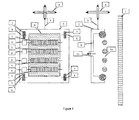
- Machine for the cleaning of surfaces mainly vertical surfaces, which comprises a body attached to the cable of a crane, brushes with an actuator attached within the body with the possibility of rotation, three or more wheels attached to the body with the possibility of rotation, this attachment being such that the working components are in the same plane, and which is characterized in that it contains a box with an open wall on the side of the surface treated, an elastic seal around the perimeter of the open part of the box and means to extract air from the box.
- the object of the invention is to improve the process of cleaning and maintaining the surfaces requiring treatment as well as extracting air from the box while it is in operation. Together with the assistance of the elastic seal located around the open part of the box, this makes it possible to exert a pressure on the surface being treated so that more uniform contact is achieved between the brushes and the surface, thus improving the quality of the cleaning process.
- the machine for cleaning surfaces comprises a body attached to the cable of a crane, brushes with one or more actuators attached on the body with the possibility of rotation and three or more wheels attached to the body with the possibility of rotation.
- the attachment is such that the working components are in the same plane and it is distinguished in that it comprises a box with an open wall on the side of the treated surface, an elastic seal around the perimeter of the open part of the box and means to extract air from the box.
- the point at which the cable is attached to the body of the machine is chosen in such a way that when the wheels bear against the vertical flat surface being treated the distance from the point of attachment of the cable to the treated surface is equal to the distance from the centre of gravity of the machine to the treated surface.
- the air extraction means are constructed in the form of a fan with an actuator attached within the body.
- the fan may comprise a filter for the air extracted from the box.
- the cross-section of the elastic seal is of curvilinear shape with one extremity attached to the walls of the box and the other extremity located outside the box.
- the wheels of the device are constructed so that they can rotate through at least 90° as a result of a special actuator. This actuator also ensures simultaneous rotation through the same angle. Some of the wheels may include means to clean the working surface of the wheels. Sensors may also be provided to measure the angle of rotation so that the position of the robot can be calculated.
- the box includes an aperture which connects to the atmosphere and a valve is fitted in this opening to open the aperture when there is a pressure difference between the atmosphere and the space within the box which exceeds a predetermined value P1, and which closes this aperture when the difference is less than a predetermined value P2.
- additional wheels Within the box there are one or more additional wheels, and these additional wheels are located in such a way that when the main wheels bear on the flat surface being treated and there is no difference in pressure between the atmosphere and the space within the box the distance between the additional wheels and the treated surface has a predetermined value L i , where i is the number of the additional wheel.
- the system for attaching the additional wheels is provided in such a way that it allows these wheels to rotate freely.
- the cleaning machine may comprise one or more tubes attached to the box. One end of these tubes opens to atmosphere and the other end is inserted into the box and ends close to the surface treated.
- the machine may be supplemented by a system which sprays a product which improves the technological process (for example a liquid) onto the surface 1 being treated.
- a product which improves the technological process (for example a liquid) onto the surface 1 being treated.
- the machine may be supplemented by a system which causes a product which improves the technological process (for example a liquid) to come into contact with brushes 5.
- a product which improves the technological process for example a liquid
- the device is operated in the following way.
- body 2 of the machine In the initial position body 2 of the machine is fixed to cable 3 of crane 4 and at some distance from surface 1 requiring treatment (for example supported on the ground at a distance from the vertical surface). With the assistance of crane 4 the machine is raised (if for example it was supported on the ground) and approaches surface 1 requiring treatment.
- the means to extract air 11 from box 9 are activated.
- a force is provided which attracts body 2 against surface 1 until the wheels 7 which have the possibility of rotating 8 (which are attached to body 2 in such a way that their working components are in the same plane) come into contact with surface 1.
- brushes 5 come into contact with surface 1 requiring treatment, with a predetermined deformation.
- Brushes 5 which are capable of rotating are driven by actuators 6 and interact with surface 1 requiring treatment, carrying out the technological process of cleaning and maintaining surface 1. While the technological cleaning and maintenance process is being carried out by brushes 5, the means to extract air 11 from box 9 are in operation. After a certain predetermined time (calculated for example with the help of a delay), body 2 of the machine moves (for example upwards or downwards) with the help of cable 3 which connects it to crane 4. During this movement means 11 for extracting air from box 9 are in operation. In this way wheels 7 which are capable of rotation 8 (which are attached to body 2 in such a way that their working components are in the same plane) bear against surface 1 requiring treatment and rotate upon the same assisting its movement.
- body 2 of the machine may be moved horizontally (to the right or to the left) through vertical upward or downward movements with the help of cable 3 linking body 2 to crane 4.
- wheels 7 may include a special actuator which allows them to rotate through at least 90° and can reduce the force of attraction provided by means 11 for extracting air from the box.
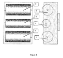
- the machine for the cleaning of vertical surfaces comprises the body attached to the cable of the crane, brushes attached to the body and with an actuator which enables them to rotate, four wheels attached to the body with the possibility of rotation.
- the attachment is such that the working components of the same are in the same plane and it is distinguished in that it comprises a box with an open wall on the side of the treated surface, with an elastic seal around the perimeter of the open part of the box and means for extracting air from the box.
- These means are constructed in the form of a fan with an actuator fixed within the body and with a filter for the air extracted from the box.
- the point of attachment of the cable to the body of the machine is chosen in such a way that when the wheels bear against the flat vertical surface treated the distance between the point at which the cable is attached and the treated surface is the same as the distance between the centre of gravity of the machine and the surface treated.
- the elastic seal has a cross-section of curvilinear shape, with one extremity fixed to the walls of the box and the other extremity located outside the box.
- the wheels of the device are constructed in such a way that they can rotate through 90° as a result of a special actuator. This actuator also ensures simultaneous rotation through the same angle.
- the central brush is marked by the fact that it has a smaller diameter than the other two.
Landscapes
- Engineering & Computer Science (AREA)
- Architecture (AREA)
- Chemical & Material Sciences (AREA)
- Chemical Kinetics & Catalysis (AREA)
- Electrochemistry (AREA)
- Mechanical Engineering (AREA)
- Civil Engineering (AREA)
- Structural Engineering (AREA)
- Cleaning In General (AREA)
Abstract
Description
Harada Mamoru.
Device for washing and cleaning wall surface of building.
Roland Morin.
Machine for cleaning vertical or inclined surfaces.
Means for automatically cleaning smooth walls and in particular the glazing of buildings.
Claims (16)
- Machine for cleaning mainly vertical surfaces which comprises a body attached to the cable of a crane, brushes with an actuator attached to the body with a possibility of rotation, three or more wheels attached to the body with the possibility of rotation, the attachment being such that its working components are in the same plane, and characterised in that it comprises a box with an open wall on the side of the surface treated, an elastic seal along the contour of the open part of the box and devices to extract air from the box.
- The device of claim 1, characterised in that the point of attachment of the cable to the body of the machine is selected in such a way that when the wheels bear against the vertical flat surface treated, the distance between the point of attachment of the cable and the surface treated is equal to the distance between the centre of gravity of the machine and the surface treated.
- The device of claims 1-2, characterised in that the air extraction devices are constructed in the form of a fan with an actuator attached within the body.
- The device of claims 1-3, characterised in that the fan comprises a filter for the air extracted from the box.
- The device of claims 1-4, characterised in that the elastic seal has a cross-section of curvilineal shape, with one extremity attached to the walls of the box and the other extremity located outside the box in such a way that when the wheels bear against the flat surface requiring cleaning the elastic seal also partly bears against that surface with a length of the same remaining parallel to the surface.
- The device of claims 1-5, characterised in that the wheels of the device are constructed with the possibility of rotating at least 90° degrees and include a special actuator.
- The device of claim 6, characterised in that the wheels include a device which ensures simultaneous rotation through at the same angle.
- The device of claims 1-7, characterised in that least some of the wheels include devices for cleaning the working surface of the wheels.
- The device of claims 1-8, characterised in that the box contains an aperture which connects it to the atmosphere and that a valve is installed in this opening which opens the aperture when there is a difference in pressure between the atmosphere and the space within the box which exceeds the predetermined value P1, and which closes this opening when there is a difference in pressure less than the predetermined value P2.
- The device of claims 1-9, characterised in that within the box there are one or more additional wheels, and these additional wheels are positioned in such a way that when the main wheels bear against the flat surface being treated and there is no difference in pressure between the atmosphere and the space within the box the distance between the additional wheels and the surface treated are predetermined values Li where i is the number of the additional wheel.
- The device of claim 10, characterised in that the system for attaching the additional wheels is constructed in such a way that it allows these wheels to rotate freely.
- The device of claims 1-11, characterised in that there are one or more tubes fixed on the box, one extremity of which opens to the atmosphere and the other extremity of which is inserted into the box and terminates close to the surface treated.
- The device of claims 1-8, 9-11, characterised in that it includes a sensor for a difference in pressure between the space within the box and the atmosphere, the devices for extraction of air from the box having a control system and the mentioned sensor being connected to this control system.
- The device of claims 1-13, characterised in that not all of the brushes placed in the same machine have the same rigidity.
- The device of claims 1-14, characterised in that at least one part of the brushes is located within the box.
- The device of claims 1-15, characterised in that at least part of the brushes contains a device for causing the brushes to bear on the surface.
Applications Claiming Priority (3)
| Application Number | Priority Date | Filing Date | Title |
|---|---|---|---|
| ES200201199 | 2002-05-24 | ||
| ES200201199A ES2215458A1 (en) | 2002-05-24 | 2002-05-24 | Surface-cleaning machine |
| PCT/ES2003/000208 WO2003100192A1 (en) | 2002-05-24 | 2003-05-09 | Surface-cleaning machine |
Publications (2)
| Publication Number | Publication Date |
|---|---|
| EP1522655A1 EP1522655A1 (en) | 2005-04-13 |
| EP1580350A1 true EP1580350A1 (en) | 2005-09-28 |
Family
ID=29558512
Family Applications (1)
| Application Number | Title | Priority Date | Filing Date |
|---|---|---|---|
| EP03722613A Withdrawn EP1580350A1 (en) | 2002-05-24 | 2003-05-09 | Surface-cleaning machine |
Country Status (14)
| Country | Link |
|---|---|
| US (1) | US7765634B2 (en) |
| EP (1) | EP1580350A1 (en) |
| JP (1) | JP4510616B2 (en) |
| KR (1) | KR20050044866A (en) |
| CN (1) | CN100359119C (en) |
| AU (1) | AU2003236215B2 (en) |
| BR (1) | BR0311234A (en) |
| CA (1) | CA2487174C (en) |
| CO (1) | CO5631469A2 (en) |
| ES (1) | ES2215458A1 (en) |
| MX (1) | MXPA04011583A (en) |
| RU (1) | RU2332156C2 (en) |
| WO (1) | WO2003100192A1 (en) |
| ZA (1) | ZA200409394B (en) |
Families Citing this family (3)
| Publication number | Priority date | Publication date | Assignee | Title |
|---|---|---|---|---|
| DE102012111149B4 (en) | 2012-11-20 | 2023-12-21 | Vorwerk & Co. Interholding Gmbh | Cleaning device |
| CN103876680B (en) * | 2013-07-08 | 2016-04-06 | 程亮然 | Spider robot |
| CN109730579B (en) * | 2019-03-05 | 2023-05-09 | 陕西科技大学 | Glass curtain wall cleaning device |
Family Cites Families (18)
| Publication number | Priority date | Publication date | Assignee | Title |
|---|---|---|---|---|
| GB1165082A (en) * | 1967-04-19 | 1969-09-24 | William Banes | Device for the Cleaning of Windows and the Outside of Buildings |
| US3641607A (en) * | 1969-03-17 | 1972-02-15 | Jerome H Lemelson | Building maintenance apparatus |
| US4025984A (en) * | 1971-04-02 | 1977-05-31 | H. H. Robertson Company | Window wall washing device for high rise buildings |
| US3831848A (en) * | 1971-11-29 | 1974-08-27 | K & M Enterprises | Spray bar with guide wheels and stabilizing poles |
| SE427535B (en) * | 1979-09-28 | 1983-04-18 | Pr Processutveckling | DEVICE FOR CLEANING OF Vertical OR LINING WALLS |
| JPS6250557A (en) * | 1985-08-27 | 1987-03-05 | 浦上 不可止 | Wall surface treatment apparatus |
| US5249326A (en) * | 1989-04-05 | 1993-10-05 | Jefferies James E | Apparatus and method for washing exterior building surfaces |
| FR2654652A1 (en) * | 1989-11-21 | 1991-05-24 | Nicolaieff Michel | Automatic apparatus for cleaning smooth walls, especially glazed walls, of buildings |
| JPH0690885A (en) * | 1991-11-25 | 1994-04-05 | Katsuaki Matsumoto | Robot for washing external wall of building |
| JP3191174B2 (en) * | 1992-04-15 | 2001-07-23 | 東芝プラント建設株式会社 | Wall or window glass cleaning equipment |
| US5240503A (en) * | 1992-04-27 | 1993-08-31 | Roni Levy | Remote-controlled system for treating external surfaces of buildings |
| JPH0810190A (en) * | 1994-06-30 | 1996-01-16 | Suzuki Motor Corp | Adsorption type wall cleaning device |
| JPH0810189A (en) * | 1994-06-30 | 1996-01-16 | Suzuki Motor Corp | Adsorption type wall cleaning device |
| JPH08150379A (en) * | 1994-11-29 | 1996-06-11 | Tohoku Green Kosan Kk | Device for washing and cleaning wall surface of building |
| JPH0966265A (en) * | 1995-08-31 | 1997-03-11 | Ishikawajima Harima Heavy Ind Co Ltd | Underwater cleaning device |
| JP3165912B2 (en) * | 1997-03-12 | 2001-05-14 | 飛島建設株式会社 | Laitance removal method and apparatus |
| CN2377989Y (en) * | 1999-05-31 | 2000-05-17 | 朱云河 | Machine for cleaning external of building such as walls, ceiling roofs, or the like |
| US6370728B1 (en) * | 2000-07-27 | 2002-04-16 | George M. Burns | Cleaning appliance |
-
2002
- 2002-05-24 ES ES200201199A patent/ES2215458A1/en active Pending
-
2003
- 2003-05-09 CA CA2487174A patent/CA2487174C/en not_active Expired - Fee Related
- 2003-05-09 MX MXPA04011583A patent/MXPA04011583A/en active IP Right Grant
- 2003-05-09 RU RU2004137812/03A patent/RU2332156C2/en not_active IP Right Cessation
- 2003-05-09 WO PCT/ES2003/000208 patent/WO2003100192A1/en not_active Ceased
- 2003-05-09 AU AU2003236215A patent/AU2003236215B2/en not_active Ceased
- 2003-05-09 BR BR0311234-9A patent/BR0311234A/en not_active Application Discontinuation
- 2003-05-09 KR KR1020047018904A patent/KR20050044866A/en not_active Abandoned
- 2003-05-09 EP EP03722613A patent/EP1580350A1/en not_active Withdrawn
- 2003-05-09 JP JP2004507626A patent/JP4510616B2/en not_active Expired - Fee Related
- 2003-05-09 US US10/515,588 patent/US7765634B2/en not_active Expired - Fee Related
- 2003-05-09 CN CNB038118432A patent/CN100359119C/en not_active Expired - Fee Related
-
2004
- 2004-11-22 ZA ZA200409394A patent/ZA200409394B/en unknown
- 2004-12-23 CO CO04128290A patent/CO5631469A2/en not_active Application Discontinuation
Non-Patent Citations (1)
| Title |
|---|
| See references of WO03100192A1 * |
Also Published As
| Publication number | Publication date |
|---|---|
| RU2332156C2 (en) | 2008-08-27 |
| CA2487174C (en) | 2011-07-26 |
| CA2487174A1 (en) | 2003-12-04 |
| AU2003236215B2 (en) | 2008-05-08 |
| ES2215458A1 (en) | 2004-10-01 |
| US7765634B2 (en) | 2010-08-03 |
| MXPA04011583A (en) | 2005-03-07 |
| US20060021167A1 (en) | 2006-02-02 |
| CN1656292A (en) | 2005-08-17 |
| CO5631469A2 (en) | 2006-04-28 |
| RU2004137812A (en) | 2005-06-10 |
| ZA200409394B (en) | 2005-06-29 |
| KR20050044866A (en) | 2005-05-13 |
| CN100359119C (en) | 2008-01-02 |
| AU2003236215A1 (en) | 2003-12-12 |
| JP2006512934A (en) | 2006-04-20 |
| BR0311234A (en) | 2005-02-22 |
| WO2003100192A1 (en) | 2003-12-04 |
| JP4510616B2 (en) | 2010-07-28 |
Similar Documents
| Publication | Publication Date | Title |
|---|---|---|
| EP2447449B1 (en) | Automated pool cleaning vehicle with middle roller | |
| CN100569390C (en) | Device and method for cleaning a rim | |
| CN109277927A (en) | Derusting device is used in a kind of protection of electronic product | |
| CN107999452A (en) | A kind of bearing cleaner | |
| US7765634B2 (en) | Surface-cleaning machine | |
| CN103949426B (en) | A kind of body cleaning machine | |
| CN109713550B (en) | Automatic enamel remover for enameled wire | |
| CN107613823B (en) | Scraper device for cleaning | |
| CN108261136A (en) | Unmanned outer wall of the building clearing apparatus | |
| NZ536888A (en) | Surface-cleaning machine | |
| IL165335A (en) | Machine for cleaning surfaces | |
| KR102482042B1 (en) | Wet mop robot vacuum cleaner | |
| JPH11169810A (en) | Surface treatment equipment | |
| CN205324305U (en) | Device of keeping a public place clean in special type vehicle jar | |
| JP2005036520A (en) | Wall moving device | |
| KR20120092967A (en) | Variable partition brush roller of cleaning apparatus for building outer wall | |
| CN115055463B (en) | Anti-shatter cleaning equipment for glass products | |
| CN217616607U (en) | Rail operation platform | |
| KR20260043742A (en) | Glass cleaning automation device | |
| KR20030035069A (en) | A glass cleaner of upper floors | |
| CN109500132B (en) | Wire surface multistage treatment process | |
| JPH0437666Y2 (en) | ||
| CN115971179A (en) | Pipeline cleaning robot suitable for complex environment | |
| CN105457957A (en) | Special vehicle in-tank cleaning device | |
| JPS60253662A (en) | Wall surface suction type decontamination apparatus |
Legal Events
| Date | Code | Title | Description |
|---|---|---|---|
| PUAI | Public reference made under article 153(3) epc to a published international application that has entered the european phase |
Free format text: ORIGINAL CODE: 0009012 |
|
| PUAB | Information related to the publication of an a document modified or deleted |
Free format text: ORIGINAL CODE: 0009199EPPU |
|
| PUAF | Information related to the publication of a search report (a3 document) modified or deleted |
Free format text: ORIGINAL CODE: 0009199SEPU |
|
| 17P | Request for examination filed |
Effective date: 20041124 |
|
| AK | Designated contracting states |
Kind code of ref document: A1 Designated state(s): AT BE BG CH CY CZ DE DK EE ES FI FR GB GR HU IE IT LI LU MC NL PT RO SE SI SK TR |
|
| AX | Request for extension of the european patent |
Extension state: AL LT LV MK |
|
| DA1 | Application published (deleted) | ||
| R17D | Deferred search report published (corrected) |
Effective date: 20031204 |
|
| PUAI | Public reference made under article 153(3) epc to a published international application that has entered the european phase |
Free format text: ORIGINAL CODE: 0009012 |
|
| 17P | Request for examination filed |
Effective date: 20041124 |
|
| AK | Designated contracting states |
Kind code of ref document: A1 Designated state(s): AT BE BG CH CY CZ DE DK EE ES FI FR GB GR HU IE IT LI LU MC NL PT RO SE SI SK TR |
|
| 17Q | First examination report despatched |
Effective date: 20081218 |
|
| STAA | Information on the status of an ep patent application or granted ep patent |
Free format text: STATUS: THE APPLICATION IS DEEMED TO BE WITHDRAWN |
|
| 18D | Application deemed to be withdrawn |
Effective date: 20121109 |