EP1580343A2 - Element for the butt joining of profiles - Google Patents
Element for the butt joining of profiles Download PDFInfo
- Publication number
- EP1580343A2 EP1580343A2 EP05005692A EP05005692A EP1580343A2 EP 1580343 A2 EP1580343 A2 EP 1580343A2 EP 05005692 A EP05005692 A EP 05005692A EP 05005692 A EP05005692 A EP 05005692A EP 1580343 A2 EP1580343 A2 EP 1580343A2
- Authority
- EP
- European Patent Office
- Prior art keywords
- profile
- butt
- joint connector
- profiles
- connector
- Prior art date
- Legal status (The legal status is an assumption and is not a legal conclusion. Google has not performed a legal analysis and makes no representation as to the accuracy of the status listed.)
- Granted
Links
Images

Classifications
-
- E—FIXED CONSTRUCTIONS
- E06—DOORS, WINDOWS, SHUTTERS, OR ROLLER BLINDS IN GENERAL; LADDERS
- E06B—FIXED OR MOVABLE CLOSURES FOR OPENINGS IN BUILDINGS, VEHICLES, FENCES OR LIKE ENCLOSURES IN GENERAL, e.g. DOORS, WINDOWS, BLINDS, GATES
- E06B3/00—Window sashes, door leaves, or like elements for closing wall or like openings; Layout of fixed or moving closures, e.g. windows in wall or like openings; Features of rigidly-mounted outer frames relating to the mounting of wing frames
- E06B3/96—Corner joints or edge joints for windows, doors, or the like frames or wings
- E06B3/964—Corner joints or edge joints for windows, doors, or the like frames or wings using separate connection pieces, e.g. T-connection pieces
- E06B3/9642—Butt type joints with at least one frame member cut off square; T-shape joints
-
- E—FIXED CONSTRUCTIONS
- E04—BUILDING
- E04B—GENERAL BUILDING CONSTRUCTIONS; WALLS, e.g. PARTITIONS; ROOFS; FLOORS; CEILINGS; INSULATION OR OTHER PROTECTION OF BUILDINGS
- E04B2/00—Walls, e.g. partitions, for buildings; Wall construction with regard to insulation; Connections specially adapted to walls
- E04B2/88—Curtain walls
- E04B2/96—Curtain walls comprising panels attached to the structure through mullions or transoms
- E04B2/965—Connections of mullions and transoms
Definitions
- the present invention relates to a butt connector for receiving Profiles, in particular post profiles and transom profiles in interior and Exterior of a thermally separated facade according to the preamble of Claim 1.
- butt connectors are both in facades for connecting the profiles the outside and inside of the facade provided.
- the butt connectors be in the respective profile on the outside or inside of the facade used, with the adjacent, usually perpendicular profile connected via the hollow chambers and screwed together.
- Previous Butt connectors had the disadvantage that for the interior and exterior of a Facade different butt connectors had to be kept ready. The same applies to external butt joints with modified glass attachment heights.
- the object of the present invention is to provide an improved To provide butt connectors, with a significant reduction of Manufacturing and storage costs can be achieved.
- the above object is the generic butt connector thereby solved that the butt connector has a single side area, the one Connection of the butt connector with outer profiles of different Glass neck heights H allows. This ensures that only one Butt connectors can be used with different glass attachment heights H. The Manufacturing costs and storage costs can be considerable be reduced.
- the side portion of the inventive Butt connector at least two to each other in the longitudinal direction of the butt connector adjacent locking positions, wherein at least one of these Locking positions of the butt connector and the outer profile with each other Intervention can be brought.
- the locking positions are here along a longitudinal recess in the side region of the butt connector.
- An advantageous embodiment of the locking positions is determined by the Use of webs achieved, which are spaced apart along the recess are arranged and embody various locking positions.
- the webs as a hook or be formed trained hook-like Vörsprüngen. These make sure that the butt connector on these hooks with corresponding projections on External profile engage.
- the butt connector according to the invention in the region of, the Hollow profile facing end have at least one recess in the engages a corresponding projection in the outer profile and the butt connector in fixed his position.
- the butt connector according to the invention is due to its special features both in the field of external profile as well as in the field the inner profile can be used.
- the butt connector for both the outer profile and the Inner profile have an identical shape.
- the manufacturing costs as well Storage costs can therefore be reduced considerably.
- FIG. 1 shows the arrangement of inventive butt connector in a thermally separated facade construction in indoor and Outdoors.
- Reference numeral 2 in Fig. 1 denotes a post profile.
- the Post profile comprises an inner profile 13 and outer profile 5, which over interposed insulators 4 to ensure thermal Separation are interconnected.
- a sealing member 17 is on one of the two insulators running parallel to this in the region of incoming latch profile 3 is provided ..
- Each one designated by the reference numeral 1 butt connector is both on External profile 5 and attached to the inner profile 13 of the post section 2 and protrudes in the direction transverse to the longitudinal course of the post section 2 before.
- the bolt profile 3 runs in the longitudinal orientation of the joint connector 1 in the Post profile 2 on.
- the bolt profile 3 has an outer profile 5 and a Inner profile 13, between each of which an insulator 4 for thermal separation the latch profile 3 is provided.
- the locking profile 3 has a notch 16, so that at a postponement of the hollow chambers of the locking bar 3 on the respective Butt joint 1 of the paragraph, which is formed by the notch 16, at the End face of the outer profile 5 is applied.
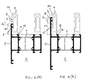
- the present invention has the butt connector, as shown in the Figures 2 (A) and (B) is clear, a uniformly formed Side region 6, which compared to the outer contour of the joint connector 1 something deepens d. H. is arranged offset inwards. Along this uniform Side area a plurality of locking positions are provided, the make it possible, the joint connector 1 with outer profiles 5 different Glass neck heights H1 or H2 to connect with each other.
- the butt connector according to the invention has the same purpose as in FIGS (A) and (B) illustrated two webs 7, which with a corresponding Tab 8 on the outer profile 5 of the post section 2 engage each other.
- the heights of the web 7 of the butt connector 1 are with the corresponding Height positions of the projection 8 on the outer profile 5 different Glass neck heights H1 or H2 adapted.
- butt connector At the top of the butt connector is an opening 14 for Fixing the incoming latch profile 3 via a corresponding (in Fig. 2 not shown) pin.
- the butt connector. 1 directly on the inside of the outer profile 5 of the post section 2.
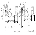
- the Verrastungsa be different shape. As in the illustrated figures, it is in this embodiment to slightly curved trained webs 7, which is a catch with the upper edge of the External profiles 5 ensure and indeed at different positions along the side portion 6 of the butt connector depending on how high the glass neck height H1 or H2 of the outer profile 5 is formed.
- the butt connector 1 in Fig. 3 (A) and (B) differs from that of Fig. 1 in that in the lower region of the joint connector two to each other resilient legs 11, 12 are provided, so that a snap of the Projection 10 in the lower recess 9 of the joint connector 1 by resilient Compressing the two legs 11, 12 takes place.
- a fixation can by a screw not shown in Figs. 3 (A) and (B), the one Squeezing the thighs.
- the shape of the opening 14 for connecting the joint connector with the Latch profile is not closed in this embodiment but one-sided open executed.
- the butt connectors according to the invention are expediently made of metal especially made of aluminum or steel. You can in particular in Case of aluminum can be made from an extruded profile. The inventive form is best suited for an extrusion process. But Aluminum die casting is also suitable for production.
- the present invention makes it possible for post profiles with different Glass neck heights H1, H2, .... to use a uniform butt joint. As a result, the manufacturing costs and storage costs in be reduced to a considerable extent.
Abstract
Description
Die vorliegende Erfindung betrifft einen Stoßverbinder zur Aufnahme von
Profilen, insbesondere Pfostenprofilen und Riegelprofilen im Innen- und
Außenbereich einer thermisch getrennten Fassade gemäß dem Oberbegriff des
Anspruchs 1.The present invention relates to a butt connector for receiving
Profiles, in particular post profiles and transom profiles in interior and
Exterior of a thermally separated facade according to the preamble of
Derartige Stoßverbinder sind bei Fassaden zur Verbindung der Profile sowohl an der Außenseite als auch Innenseite der Fassade vorgesehen. Die Stoßverbinder werden in das jeweilige Profil an der Außen- bzw. Innenseite der Fassade eingesetzt, mit dem benachbarten, in der Regel rechtwinklig verlaufenden Profil über deren Hohlkammern verbunden und miteinander verschraubt. Bisherige Stoßverbinder hatten den Nachteil, dass für den Innen- und Außenbereich einer Fassade unterschiedliche Stoßverbinder bereitgehalten werden mussten. Gleiches gilt für Stoßverbinder im Außenbereich bei sich veränderter Glasansatzhöhen.Such butt connectors are both in facades for connecting the profiles the outside and inside of the facade provided. The butt connectors be in the respective profile on the outside or inside of the facade used, with the adjacent, usually perpendicular profile connected via the hollow chambers and screwed together. Previous Butt connectors had the disadvantage that for the interior and exterior of a Facade different butt connectors had to be kept ready. The same applies to external butt joints with modified glass attachment heights.
Die Aufgabe der vorliegenden Erfindung besteht darin, einen verbesserten Stoßverbinder zur Verfügung zu stellen, mit dem eine erhebliche Reduzierung der Herstellungs- und Lagerhaltungskosten erzielt werden kann.The object of the present invention is to provide an improved To provide butt connectors, with a significant reduction of Manufacturing and storage costs can be achieved.
Die vorstehende Aufgabe wird beim gattungsgemäßen Stoßverbinder dadurch gelöst, dass der Stoßverbinder einen einheitlichen Seitenbereich aufweist, der eine Verbindung des Stoßverbinders mit Außenprofilen unterschiedlicher Glasansatzhöhen H ermöglicht. Hierdurch wird gewährleistet, dass lediglich ein Stoßverbinder bei verschiedenen Glasansatzhöhen H eingesetzt werden kann. Die Herstellungskosten sowie Lagerhaltungskosten können hierbei beträchtlich reduziert werden.The above object is the generic butt connector thereby solved that the butt connector has a single side area, the one Connection of the butt connector with outer profiles of different Glass neck heights H allows. This ensures that only one Butt connectors can be used with different glass attachment heights H. The Manufacturing costs and storage costs can be considerable be reduced.
Zweckmäßigerweise umfasst der Seitenbereich des erfindungsgemäßen Stoßverbinders mindestens zwei zueinander in Längsrichtung des Stoßverbinders benachbarte Verriegelungspositionen, wobei an mindestens einer dieser Verriegelungspositionen der Stoßverbinder und das Außenprofil miteinander ein Eingriff bringbar sind.Conveniently, the side portion of the inventive Butt connector at least two to each other in the longitudinal direction of the butt connector adjacent locking positions, wherein at least one of these Locking positions of the butt connector and the outer profile with each other Intervention can be brought.
Die Verriegelungspositionen befinden sich hierbei entlang einer längsverlaufenden Vertiefung im Seitenbereich des Stoßverbinders.The locking positions are here along a longitudinal recess in the side region of the butt connector.
Hierdurch wird gewährleistet, dass der nach innen gerichtete Vorsprung am Außenprofil in die gewünschte Verriegelungsposition bringbar ist.This ensures that the inward projection on External profile can be brought into the desired locking position.
Eine vorteilhafte Ausgestaltung der Verriegelungspositionen wird durch den Einsatz von Stegen erzielt, die voneinander beabstandet entlang der Vertiefung angeordnet sind und verschiedene Verriegelungspositionen verkörpern.An advantageous embodiment of the locking positions is determined by the Use of webs achieved, which are spaced apart along the recess are arranged and embody various locking positions.
Zur Gewährleistung der Verriegelungspositionen können die Stege als Haken oder hakenartigen Vörsprüngen ausgebildet ausgebildet sein. Diese dafür sorgen dafür, dass der Stoßverbinder über diese Haken mit entsprechenden Vorsprüngen am Außenprofil in Eingriff treten.To ensure the locking positions, the webs as a hook or be formed trained hook-like Vörsprüngen. These make sure that the butt connector on these hooks with corresponding projections on External profile engage.
Ferner kann der erfindungsgemäße Stoßverbinder im Bereich seines, dem Hohlprofil zugewandten Endes mindestens eine Ausnehmung aufweisen, in die ein entsprechender Vorsprung im Außenprofil eingreift und den Stoßverbinder in seiner Lage fixiert.Furthermore, the butt connector according to the invention in the region of, the Hollow profile facing end have at least one recess in the engages a corresponding projection in the outer profile and the butt connector in fixed his position.
Des weiteren können am Stoßverbinder zur Fixierung desselben am Profil zwei zueinander federnde Schenkel vorgesehen sein. Dies hat den Vorteil, dass der jeweilige Stoßverbinder auch noch nachträglich, d. h. bei bereits verbundenem Rahmen eingesetzt werden kann. Furthermore, on the butt connector for fixing the same on the profile two be provided to each other resilient leg. This has the advantage that the respective butt joints also subsequently, d. H. at already connected Frame can be used.
Zweckmäßigerweise ist der erfindungsgemäße Stoßverbinder aufgrund seiner besonderen Merkmale sowohl im Bereich des Außenprofils als auch im Bereich des Innenprofils einsetzbar.Conveniently, the butt connector according to the invention is due to its special features both in the field of external profile as well as in the field the inner profile can be used.
Insbesondere kann der Stoßverbinder sowohl für das Außenprofil als auch das Innenprofil eine identische Form aufweisen. Die Herstellungskosten sowie Lagerhaltungskosten können demzufolge in erheblicher Weise reduziert werden.In particular, the butt connector for both the outer profile and the Inner profile have an identical shape. The manufacturing costs as well Storage costs can therefore be reduced considerably.
Nachstehend werden anhand von Zeichnungsfiguren mehrere zweckmäßige Ausgestaltungen der vorliegenden Erfindung näher erläutert. Wiederkehrende Merkmale sind der Übersichtlichkeit halber lediglich einmal mit Bezugszeichen versehen. Es zeigen:
- Fig. 1
- eine perspektivische Darstellung eines Pfostenprofils sowie Riegelprofils, welche durch erfindungsgemäße Stoßverbinder miteinander verbunden werden;
- Fig. 2
- eine Schnittdarstellung durch ein Pfostenprofil mit jeweils angesetzten Stoßverbindern mit einer ersten Glasansatzhöhe H1 gemäß Fig. 2 (A) sowie einer zweiten Glasansatzhöhe H2 gemäß Fig. 2 (B) sowie
- Fig. 3
- eine Schnittdarstellung durch ein Pfostenprofil mit jeweils angesetzten Stoßverbindern mit einer ersten Glasansatzhöhe H1 gemäß Fig Fig. 3 (A) sowie einer zweiten Glasansatzhöhe H2 gemäß Fig Fig. 3 (B) einer weiteren Ausgestaltung;
- Fig. 1
- a perspective view of a post profile and latch profile, which are interconnected by butt connector according to the invention;
- Fig. 2
- a sectional view through a post profile with each attached shock connectors with a first glass approach height H1 of FIG. 2 (A) and a second glass approach height H2 shown in FIG. 2 (B) and
- Fig. 3
- a sectional view through a post profile, each with attached butt connectors with a first glass approach height H1 according to FIG. 3 (A) and a second glass attachment height H2 according to FIG. 3 (B) of a further embodiment;
Die Darstellung in Fig. 1 zeigt die Anordnung erfindungsgemäßer Stoßverbinder
bei einer thermisch getrennten Fassadenkonstruktion im Innen- und
Außenbereich. Bezugsziffer 2 in Fig. 1 bezeichnet ein Pfostenprofil. Das
Pfostenprofil umfasst ein Innenprofil 13 sowie Außenprofil 5, welche über
dazwischen angeordneten Isolatoren 4 zur Gewährleistung einer thermischen
Trennung miteinander verbunden sind. Darüber hinaus ist ein Dichtteil 17 an
einem der beiden Isolatoren parallel zu diesem verlaufend im Bereich des
einlaufenden Riegelprofils 3 vorgesehen..The illustration in Fig. 1 shows the arrangement of inventive butt connector
in a thermally separated facade construction in indoor and
Outdoors.
Je ein mit der Bezugsziffer 1 bezeichneter Stoßverbinder ist sowohl am
Außenprofil 5 als auch am Innenprofil 13 des Pfostenprofils 2 angesetzt und ragt
in Richtung quer zum Längsverlauf des Pfostenprofils 2 vor.Each one designated by the
Das Riegelprofil 3, läuft in der Längsorientierung des Stoßverbinders 1 in das
Pfostenprofil 2 ein. Auch das Riegelprofil 3 besitzt ein Außenprofil 5 sowie ein
Innenprofil 13, zwischen denen jeweils ein Isolator 4 zur thermischen Trennung
des Riegelprofils 3 vorgesehen ist.The
Im Bereich der Außenseite besitzt das Riegelprofil 3 eine Ausklinkung 16, so dass
bei einem Aufschieben der Hohlkammern des Riegelprofils 3 auf den jeweiligen
Stoßverbinder 1 der Absatz, der durch die Ausklinkung 16 gebildet ist, an der
Stirnseite des Außenprofils 5 anliegt. Sind das Pfostenprofil 2 sowie Riegelprofil
3 auf diese Art und Weise miteinander zusammengesetzt worden, erfolgt eine
Verschraubung über jeweils in eine Lochung 17 eingeführte Stifte 19, z. B.
Schraubstifte, die in eine entsprechende Öffnung 14 am Stoßverbinder eingreifen.
Zusätzlich kann, wie in Fig. 1 vorgesehen, eine Verklebung mittels eines über
einen Kanal 18 eingebrachten Klebstoffs erfolgen.In the area of the outside, the
Gemäß der vorliegenden Erfindung besitzt der Stoßverbinder, wie dies in den
Figuren 2 (A) sowie (B) deutlich wird, einen einheitlich ausgebildeten
Seitenbereich 6, der im Vergleich zur Außenkontur des Stoßverbinders 1 etwas
vertieft d. h. nach innen versetzt angeordnet ist. Entlang dieses einheitlichen
Seitenbereichs sind eine Mehrzahl von Verriegelungspositionen vorgesehen, die
es ermöglichen, den Stoßverbinder 1 mit Außenprofilen 5 unterschiedlicher
Glasansatzhöhen H1 bzw. H2 miteinander zu verbinden.According to the present invention has the butt connector, as shown in the
Figures 2 (A) and (B) is clear, a uniformly formed
Konkret weist der erfindungsgemäße Stoßverbinder hierzu wie in den Figuren 2
(A) bzw. (B) dargestellt zwei Stege 7 auf, die mit einem entsprechenden
Vorsprung 8 am Außenprofil 5 des Pfostenprofils 2 miteinander in Eingriff treten.
Die Höhen des Stegs 7 des Stoßverbinders 1 sind mit den entsprechenden
Höhenpositionen des Vorsprungs 8 am Außenprofil 5 unterschiedlicher
Glasansatzhöhen H1 bzw. H2 angepasst.In concrete terms, the butt connector according to the invention has the same purpose as in FIGS
(A) and (B) illustrated two
Zur Gewährleistung einer Verrastung sind die Stege 7 hakenartig ausgebildet.
Gleiches gilt für die Vorsprünge 8 am Außenprofil 5. Diese sind in der
Ausgestaltung nach Fig. 2 (A) sowie (B) als eine Art Doppelhaken vorgesehen.To ensure locking the
An der Oberseite des Stoßverbinders befindet sich eine Öffnung 14 zur
Befestigung des einlaufenden Riegelprofil 3 über einen entsprechenden (in Fig. 2
nicht dargestellten) Stift. Unterhalb des Seitenbereichs 6 liegt der Stoßverbinder 1
unmittelbar an der Innenseite des Außenprofils 5 des Pfostenprofils 2 an.At the top of the butt connector is an
Zur Verbindung des Stoßverbinders im Profilgrund des Außenprofils 5 weist
dieser eine seitliche Ausnehmung 9 auf, in die ein entsprechend geformter
Vorsprung 10 des Außenprofils 5 eingreift.For connecting the joint connector in the profile base of the
Wie auch aus den Fig. 2 (A) sowie (B) zu entnehmen ist, besitzen die
Stoßverbinder 1 für den Innen- sowie Außenbereich gleiche Form und können
demzufolge lediglich in dieser Form hergestellt und lagertechnisch bereitgehalten
werden. Sie können sowohl innen als auch aussen verwendet werden und
gleichzeitig für Außenprofile mit unterschiedlicher Glasansatzhöhe H1, H2.....
eingesetzt werden. As can be seen also from Figs. 2 (A) and (B), have the
Im Bereich der einheitlich ausgebildeten Vertiefung 15 können mehr
Verrastungsmöglichkeiten als die in Fig. 2(A) bzw. 2(B) gezeigten vorgesehen
sein.In the area of uniformly formed
Wie den Fig. 3 (A) sowie (B) zu entnehmen ist, können die
Verrastungsmöglichkeiten unterschiedlicher Gestalt sein. Wie in den
vorerwähnten Figuren dargestellt, handelt es sich bei dieser Ausgestaltung um
leicht gekrümmt ausgebildete Stege 7, der eine Verrastung mit der Oberkante des
Außenprofils 5 gewährleisten und zwar an unterschiedlichen Positionen entlang
des Seitenbereichs 6 des Stoßverbinders je nach dem wie hoch die Glasansatzhöhe
H1 bzw. H2 des Außenprofils 5 ausgebildet ist.As can be seen in FIGS. 3 (A) and (B), the
Verrastungsmöglichkeiten be different shape. As in the
illustrated figures, it is in this embodiment to
slightly curved trained
Darüber hinaus unterscheidet sich der Stoßverbinder 1 in Fig. 3 (A) bzw. (B) von
demjenigen der Fig. 1 dadurch, dass im unteren Bereich des Stoßverbinders zwei
zueinander federnde Schenkel 11, 12 vorgesehen sind, so dass ein Einrasten des
Vorsprungs 10 in die untere Ausnehmung 9 des Stoßverbinders 1 durch federndes
Zusammendrücken der beiden Schenkel 11, 12 erfolgt. Eine Fixierung kann durch
eine in den Fig. 3 (A) sowie (B) nicht dargestellte Schraube erfolgen, die ein
Zusammendrücken der Schenkel unterbindet.In addition, the
Auch die Form der Öffnung 14 zur Verbindung des Stoßverbinders mit dem
Riegelprofil ist in dieser Ausgestaltung nicht geschlossen sondern einseitig offen
ausgeführt.Also, the shape of the
Die erfindungsgemäßen Stoßverbinder werden zweckmäßigerweise aus Metall insbesondere aus Aluminium oder Stahl hergestellt. Sie können insbesondere im Fall von Aluminium aus einem Strangpressprofil gefertigt werden. Die erfindungsgemäße Form ist für ein Strangpressverfahren bestens geeignet. Aber auch Aluminiumdruckguss ist zur Herstellung geeignet. The butt connectors according to the invention are expediently made of metal especially made of aluminum or steel. You can in particular in Case of aluminum can be made from an extruded profile. The inventive form is best suited for an extrusion process. But Aluminum die casting is also suitable for production.
Es wird ausdrücklich darauf hingewiesen, dass von der erfindungsgemäßen Idee auch die Kombination von Teilmerkmalen des erfindungsgemäßen Stoßverbinders, wie sie dem Gesamtinhalt dieser Patentanmeldung zu entnehmen sind, umfasst sind.It is expressly pointed out that of the inventive idea also the combination of partial features of the invention Butt joint, as can be seen in the overall content of this patent application are included.
Die vorliegende Erfindung ermöglicht es, für Pfostenprofile mit unterschiedlichen Glasansatzhöhen H1, H2,.... einen einheitlichen Stoßverbinder zu verwenden. Hierdurch können die Herstellungskosten sowie Lagerhaltungskosten in erheblichem Umfang reduziert werden. The present invention makes it possible for post profiles with different Glass neck heights H1, H2, .... to use a uniform butt joint. As a result, the manufacturing costs and storage costs in be reduced to a considerable extent.
- 11
- StoßverbinderrStoßverbinderr
- 22
- Pfostenprofilpost profile
- 33
- Riegelprofiltransom profile
- 44
- Isolatorinsulator
- 55
- Außenprofilouter profile
- 66
- Seitenbereichpage range
- 77
- Stegweb
- 88th
- Vorsprunghead Start
- 99
- Ausnehmungrecess
- 1010
- Vorsprunghead Start
- 1111
- Schenkelleg
- 1212
- Schenkelleg
- 1313
- Innenprofilinternal profile
- 1414
- Öffnungopening
- 1515
- Vertiefungdeepening
- 1616
- Ausklinkungnotch
- 1717
- Lochungperforation
- 1818
- Kanalchannel
- 1919
- Stiftpen
Claims (10)
dadurch gekennzeichnet, dass
der Stoßverbinder (1) einen einheitlichen Seitenbereich (6) umfasst, der eine Verbindung desselben Stoßverbinders (1) mit den Außenprofilen (5) ermöglicht, wobei die Außenprofile (5) unterschiedliche Glasansatzhöhen H aufweisen.Butt joint (1) for connecting profiles, in particular post profiles (2) and transom profiles (3) in the interior and exterior of a, in particular thermally separated, facade with means for the frontal connection of the joint connector (1) with the profile to be joined,
characterized in that
the joint connector (1) comprises a uniform side region (6) which allows a connection of the same joint connector (1) to the outer profiles (5), wherein the outer profiles (5) have different glass neck heights H.
dadurch gekennzeichnet, dass
der Seitenbereich (6) mindestens zwei, zueinander in Längsrichtung des Stoßverbinders (1) benachbarte Verriegelungspositionen aufweist, wobei an mindestens einer dieser Verriegelungspositionen der Stoßverbinder (1) und das Außenprofil (5) miteinander in Eingriff bringbar sind. Joint connector according to claim 1,
characterized in that
the side region (6) has at least two locking positions adjacent to one another in the longitudinal direction of the joint connector (1), wherein the butt connector (1) and the outer profile (5) can be brought into engagement with one another at at least one of these locking positions.
dadurch gekennzeichnet, dass
die Verriegelungspositionen im Vergleich zur Anlageebene von Außenprofil (5) und Stoßverbinder (1) nach innen versetzt sind.Joint connector according to claim 2,
characterized in that
the locking positions are offset in relation to the contact plane of outer profile (5) and butt connector (1) inwards.
dadurch gekennzeichnet, dass
die Verriegelungspositionen durch Stege (7) gebildet sind.Joint connector according to claim 2 or 3,
characterized in that
the locking positions are formed by webs (7).
dadurch gekennzeichnet, dass
die Stege (3) als Haken ausgebildet sind, die in Eingriff mit Vorsprüngen (8) am Außenprofil (5) bringbar sind.Joint connector according to claim 4,
characterized in that
the webs (3) are designed as hooks which can be brought into engagement with projections (8) on the outer profile (5).
dadurch gekennzeichnet, dass
im Bereich eines, dem Hohlprofil zugewandten Endes mindestens eine Ausnehmung (9) vorgesehen ist, in die ein entsprechender Vorsprung (10) am Außenprofil (5) eingreift und den Stoßverbinder (1) in seiner Lage fixiert.Joint connector according to claims 1 - 5,
characterized in that
at least one recess (9) is provided in the region of an end facing the hollow profile, in which a corresponding projection (10) on the outer profile (5) engages and fixes the butt connector (1) in its position.
dadurch gekennzeichnet, dass
der Stoßverbinder (1) zueinander federnde Schenkel (11, 12) aufweist.Joint connector according to claims 1 - 6,
characterized in that
the butt connector (1) has mutually resilient legs (11, 12).
dadurch gekennzeichnet, dass
der Stoßverbinder (1) sowohl für das Außenprofil (5) als auch für das Innenprofil verwendbar ist.Joint connector according to claims 1 - 7,
characterized in that
the butt connector (1) can be used both for the outer profile (5) and for the inner profile.
dadurch gekennzeichnet, dass
der Stoßverbinder für das Außenprofil (5) sowie Innenprofil (13) identische Form besitzt. Joint connector according to claims 1 - 8,
characterized in that
the butt connector for the outer profile (5) and inner profile (13) has identical shape.
dadurch gekennzeichnet, dass
der Stoßverbinder ein Strangpressteil insbesondere ein Aluminium-Strangpressteil ist.Joint connector according to claims 1 - 9,
characterized in that
the butt connector is an extrusion, in particular an aluminum extrusion.
Applications Claiming Priority (2)
| Application Number | Priority Date | Filing Date | Title |
|---|---|---|---|
| DE102004014598A DE102004014598B4 (en) | 2004-03-23 | 2004-03-23 | Butt connector for connecting profiles |
| DE102004014598 | 2004-03-23 |
Publications (3)
| Publication Number | Publication Date |
|---|---|
| EP1580343A2 true EP1580343A2 (en) | 2005-09-28 |
| EP1580343A3 EP1580343A3 (en) | 2006-10-04 |
| EP1580343B1 EP1580343B1 (en) | 2008-02-06 |
Family
ID=34854043
Family Applications (1)
| Application Number | Title | Priority Date | Filing Date |
|---|---|---|---|
| EP05005692A Not-in-force EP1580343B1 (en) | 2004-03-23 | 2005-03-16 | Element for the butt joining of profiles |
Country Status (3)
| Country | Link |
|---|---|
| EP (1) | EP1580343B1 (en) |
| AT (1) | ATE385529T1 (en) |
| DE (2) | DE102004014598B4 (en) |
Cited By (3)
| Publication number | Priority date | Publication date | Assignee | Title |
|---|---|---|---|---|
| EP2322732A1 (en) | 2009-11-16 | 2011-05-18 | W.M.K.Secur S.r.l. | Facade or glass wall in fire safety construction |
| CN105822196A (en) * | 2016-06-14 | 2016-08-03 | 无锡王兴幕墙装饰工程有限公司 | Cross connection structure |
| EP3163002A1 (en) * | 2015-11-02 | 2017-05-03 | Kawneer Aluminium Deutschland Inc. | Connecting element for door and window frames |
Families Citing this family (4)
| Publication number | Priority date | Publication date | Assignee | Title |
|---|---|---|---|---|
| DE102007002605A1 (en) * | 2007-01-12 | 2008-07-17 | Eduard Hueck Gmbh & Co Kg | Connector for joining window or facade profiles comprises a first section with a first connecting unit and a second section with a sealing unit |
| DE202008014975U1 (en) * | 2008-11-12 | 2010-04-01 | Raico Bautechnik Gmbh | T-connection between a mullion and transom profile |
| DE102010033845A1 (en) * | 2010-08-11 | 2012-02-16 | Eduard Hueck Gmbh & Co. Kg | Profile arrangement for post and beam construction, has profiles, connector that is provided for connection of profiles, and tensioning device adapted to press one of profiles in direction of another profile |
| DE202012005444U1 (en) | 2012-04-05 | 2012-07-03 | Heroal - Johann Henkenjohann Gmbh & Co. Kg | Butt joint preferably a window frame |
Citations (4)
| Publication number | Priority date | Publication date | Assignee | Title |
|---|---|---|---|---|
| EP0614018A2 (en) * | 1993-03-02 | 1994-09-07 | SCHÜCO International KG | T connection between two profiles |
| EP0614019A2 (en) * | 1993-03-02 | 1994-09-07 | SCHÜCO International KG | T connection between two profiles |
| EP0748919A2 (en) * | 1995-06-17 | 1996-12-18 | SCHÜCO International KG | T-connector for exterior metal parts of insulated frame members for doors, windows or facades |
| EP1245777A2 (en) * | 2001-03-28 | 2002-10-02 | Norsk Hydro Asa | Corner or butt joint |
Family Cites Families (2)
| Publication number | Priority date | Publication date | Assignee | Title |
|---|---|---|---|---|
| DE9116213U1 (en) * | 1991-08-06 | 1992-07-23 | Philippi, Gerd, 6632 Saarwellingen, De | |
| DE19849152C5 (en) * | 1998-10-26 | 2013-10-10 | Gutmann Ag | Post and rail connection |
-
2004
- 2004-03-23 DE DE102004014598A patent/DE102004014598B4/en not_active Expired - Fee Related
-
2005
- 2005-03-16 DE DE502005002742T patent/DE502005002742D1/en active Active
- 2005-03-16 AT AT05005692T patent/ATE385529T1/en active
- 2005-03-16 EP EP05005692A patent/EP1580343B1/en not_active Not-in-force
Patent Citations (4)
| Publication number | Priority date | Publication date | Assignee | Title |
|---|---|---|---|---|
| EP0614018A2 (en) * | 1993-03-02 | 1994-09-07 | SCHÜCO International KG | T connection between two profiles |
| EP0614019A2 (en) * | 1993-03-02 | 1994-09-07 | SCHÜCO International KG | T connection between two profiles |
| EP0748919A2 (en) * | 1995-06-17 | 1996-12-18 | SCHÜCO International KG | T-connector for exterior metal parts of insulated frame members for doors, windows or facades |
| EP1245777A2 (en) * | 2001-03-28 | 2002-10-02 | Norsk Hydro Asa | Corner or butt joint |
Cited By (3)
| Publication number | Priority date | Publication date | Assignee | Title |
|---|---|---|---|---|
| EP2322732A1 (en) | 2009-11-16 | 2011-05-18 | W.M.K.Secur S.r.l. | Facade or glass wall in fire safety construction |
| EP3163002A1 (en) * | 2015-11-02 | 2017-05-03 | Kawneer Aluminium Deutschland Inc. | Connecting element for door and window frames |
| CN105822196A (en) * | 2016-06-14 | 2016-08-03 | 无锡王兴幕墙装饰工程有限公司 | Cross connection structure |
Also Published As
| Publication number | Publication date |
|---|---|
| ATE385529T1 (en) | 2008-02-15 |
| EP1580343A3 (en) | 2006-10-04 |
| DE502005002742D1 (en) | 2008-03-20 |
| DE102004014598B4 (en) | 2006-07-27 |
| EP1580343B1 (en) | 2008-02-06 |
| DE102004014598A1 (en) | 2005-10-27 |
Similar Documents
| Publication | Publication Date | Title |
|---|---|---|
| DE102005044980B4 (en) | Butt connector for wood / aluminum facades | |
| DE4210456C2 (en) | Cross connection for profile bars using tension members | |
| EP2476853B1 (en) | Connecting section for windows, doors and façades as well as method for producing the same | |
| EP1580343B1 (en) | Element for the butt joining of profiles | |
| DE3112365A1 (en) | Wedge-shaped connecting element for the quick and firm connection of profiles | |
| DE4223898A1 (en) | Roof rails for vehicles | |
| EP2738317A1 (en) | Wall construction panel element | |
| EP0976891B1 (en) | Construction system | |
| DE102005001986A1 (en) | Modular facade for building, glass mounting seal and screw | |
| DE2516036C3 (en) | Multi-part profile rod, insulated against heat transmission, for exterior wall constructions | |
| DE202006004607U1 (en) | Frame construction for a composite of frame beams component | |
| DE19828382C2 (en) | Arrangement for fastening a post having a hollow cross section to the window frame of a window or a door made of plastic or light metal | |
| DE19513623A1 (en) | Building facade glazing suspension | |
| EP1500827A1 (en) | Modular construction system | |
| EP1491696B1 (en) | System for joining profiles | |
| EP4012132B1 (en) | T-connection for post-beam structure and a post-beam structure with such a t-connection | |
| DE19940574C1 (en) | The lateral bond between a cross post and the longitudinal post of a window/door has a divided longitudinal post forming a T-structure containing an eye bolt into the mounting bolt tightened by an eccentric shaft | |
| DE2604814A1 (en) | Insulating window or door bar piece connector - comprising two bolt linked parts with hooks engaging interfacing ribs | |
| DE10156898A1 (en) | Holding element for window frames etc. has at least one body including extruded element | |
| DE102020106891B4 (en) | T-connection between a mullion and transom profile and a mullion-transom construction with such a T-connection | |
| DE3128505A1 (en) | Device for the junction connection of wooden framework bars | |
| DE10229272A1 (en) | Butt connector for angled connection of hollow profiles such as facades, roofs, windows and suchlike has holding element fastened to connecting section and with fixing pin which as material forming is component part of holding element | |
| DE102004055556B4 (en) | Connecting element for profiles | |
| DE2447936A1 (en) | FOLDABLE WALL ELEMENT | |
| DE202021106848U1 (en) | Modular lattice railing for a French balcony |
Legal Events
| Date | Code | Title | Description |
|---|---|---|---|
| PUAI | Public reference made under article 153(3) epc to a published international application that has entered the european phase |
Free format text: ORIGINAL CODE: 0009012 |
|
| AK | Designated contracting states |
Kind code of ref document: A2 Designated state(s): AT BE BG CH CY CZ DE DK EE ES FI FR GB GR HU IE IS IT LI LT LU MC NL PL PT RO SE SI SK TR |
|
| AX | Request for extension of the european patent |
Extension state: AL BA HR LV MK YU |
|
| RAP1 | Party data changed (applicant data changed or rights of an application transferred) |
Owner name: HERMANN GUTMANN WERKE AG |
|
| PUAL | Search report despatched |
Free format text: ORIGINAL CODE: 0009013 |
|
| AK | Designated contracting states |
Kind code of ref document: A3 Designated state(s): AT BE BG CH CY CZ DE DK EE ES FI FR GB GR HU IE IS IT LI LT LU MC NL PL PT RO SE SI SK TR |
|
| AX | Request for extension of the european patent |
Extension state: AL BA HR LV MK YU |
|
| 17P | Request for examination filed |
Effective date: 20070306 |
|
| AKX | Designation fees paid |
Designated state(s): AT CH DE LI |
|
| GRAP | Despatch of communication of intention to grant a patent |
Free format text: ORIGINAL CODE: EPIDOSNIGR1 |
|
| GRAS | Grant fee paid |
Free format text: ORIGINAL CODE: EPIDOSNIGR3 |
|
| GRAA | (expected) grant |
Free format text: ORIGINAL CODE: 0009210 |
|
| AK | Designated contracting states |
Kind code of ref document: B1 Designated state(s): AT CH DE LI |
|
| REG | Reference to a national code |
Ref country code: CH Ref legal event code: EP |
|
| REF | Corresponds to: |
Ref document number: 502005002742 Country of ref document: DE Date of ref document: 20080320 Kind code of ref document: P |
|
| PLBE | No opposition filed within time limit |
Free format text: ORIGINAL CODE: 0009261 |
|
| STAA | Information on the status of an ep patent application or granted ep patent |
Free format text: STATUS: NO OPPOSITION FILED WITHIN TIME LIMIT |
|
| 26N | No opposition filed |
Effective date: 20081107 |
|
| REG | Reference to a national code |
Ref country code: CH Ref legal event code: NV Representative=s name: PATENTANWAELTE SCHAAD, BALASS, MENZL & PARTNER AG Ref country code: CH Ref legal event code: PFA Owner name: GUTMANN AG Free format text: HERMANN GUTMANN WERKE AG#NUERNBERGER STRASSE 57-81#91781 WEISSENBURG (DE) -TRANSFER TO- GUTMANN AG#NUERNBERGER STRASSE 57#91781 WEISSENBURG (DE) |
|
| REG | Reference to a national code |
Ref country code: DE Ref legal event code: R081 Ref document number: 502005002742 Country of ref document: DE Owner name: GUTMANN AG, DE Free format text: FORMER OWNER: HERMANN GUTMANN WERKE AG, 91781 WEISSENBURG, DE Effective date: 20110311 |
|
| PGFP | Annual fee paid to national office [announced via postgrant information from national office to epo] |
Ref country code: AT Payment date: 20110323 Year of fee payment: 7 |
|
| PGFP | Annual fee paid to national office [announced via postgrant information from national office to epo] |
Ref country code: CH Payment date: 20120323 Year of fee payment: 8 |
|
| PGFP | Annual fee paid to national office [announced via postgrant information from national office to epo] |
Ref country code: DE Payment date: 20120316 Year of fee payment: 8 |
|
| REG | Reference to a national code |
Ref country code: AT Ref legal event code: MM01 Ref document number: 385529 Country of ref document: AT Kind code of ref document: T Effective date: 20120316 |
|
| PG25 | Lapsed in a contracting state [announced via postgrant information from national office to epo] |
Ref country code: AT Free format text: LAPSE BECAUSE OF NON-PAYMENT OF DUE FEES Effective date: 20120316 |
|
| REG | Reference to a national code |
Ref country code: CH Ref legal event code: PL |
|
| REG | Reference to a national code |
Ref country code: DE Ref legal event code: R119 Ref document number: 502005002742 Country of ref document: DE Effective date: 20131001 |
|
| PG25 | Lapsed in a contracting state [announced via postgrant information from national office to epo] |
Ref country code: CH Free format text: LAPSE BECAUSE OF NON-PAYMENT OF DUE FEES Effective date: 20130331 Ref country code: DE Free format text: LAPSE BECAUSE OF NON-PAYMENT OF DUE FEES Effective date: 20131001 Ref country code: LI Free format text: LAPSE BECAUSE OF NON-PAYMENT OF DUE FEES Effective date: 20130331 |