EP1580296B1 - Reduced thermal conductivity TBC by EB-PVD process to incorporate porosity - Google Patents
Reduced thermal conductivity TBC by EB-PVD process to incorporate porosity Download PDFInfo
- Publication number
- EP1580296B1 EP1580296B1 EP20050251745 EP05251745A EP1580296B1 EP 1580296 B1 EP1580296 B1 EP 1580296B1 EP 20050251745 EP20050251745 EP 20050251745 EP 05251745 A EP05251745 A EP 05251745A EP 1580296 B1 EP1580296 B1 EP 1580296B1
- Authority
- EP
- European Patent Office
- Prior art keywords
- tbc
- layers
- fugitive material
- depositing
- matrix
- Prior art date
- Legal status (The legal status is an assumption and is not a legal conclusion. Google has not performed a legal analysis and makes no representation as to the accuracy of the status listed.)
- Expired - Lifetime
Links
- 238000000034 method Methods 0.000 title claims abstract description 39
- 239000000463 material Substances 0.000 claims abstract description 63
- 239000012720 thermal barrier coating Substances 0.000 claims abstract description 60
- 239000011159 matrix material Substances 0.000 claims abstract description 31
- 238000010438 heat treatment Methods 0.000 claims abstract description 24
- 238000000151 deposition Methods 0.000 claims abstract description 19
- 239000000203 mixture Substances 0.000 claims abstract description 12
- 238000010348 incorporation Methods 0.000 claims abstract description 3
- 238000005328 electron beam physical vapour deposition Methods 0.000 claims description 15
- ZOKXTWBITQBERF-UHFFFAOYSA-N Molybdenum Chemical compound [Mo] ZOKXTWBITQBERF-UHFFFAOYSA-N 0.000 claims description 8
- 239000000919 ceramic Substances 0.000 claims description 8
- 229910052750 molybdenum Inorganic materials 0.000 claims description 8
- 239000011733 molybdenum Substances 0.000 claims description 8
- 239000011148 porous material Substances 0.000 claims description 7
- OKTJSMMVPCPJKN-UHFFFAOYSA-N Carbon Chemical compound [C] OKTJSMMVPCPJKN-UHFFFAOYSA-N 0.000 claims description 5
- 229910052799 carbon Inorganic materials 0.000 claims description 5
- 230000008018 melting Effects 0.000 claims description 5
- 238000002844 melting Methods 0.000 claims description 5
- 238000010894 electron beam technology Methods 0.000 claims description 4
- 230000004888 barrier function Effects 0.000 claims description 3
- 238000001704 evaporation Methods 0.000 claims description 3
- QCWXUUIWCKQGHC-UHFFFAOYSA-N Zirconium Chemical compound [Zr] QCWXUUIWCKQGHC-UHFFFAOYSA-N 0.000 claims description 2
- 238000005137 deposition process Methods 0.000 claims description 2
- 150000001247 metal acetylides Chemical class 0.000 claims description 2
- 150000004767 nitrides Chemical class 0.000 claims description 2
- 229910021332 silicide Inorganic materials 0.000 claims description 2
- WFKWXMTUELFFGS-UHFFFAOYSA-N tungsten Chemical compound [W] WFKWXMTUELFFGS-UHFFFAOYSA-N 0.000 claims description 2
- 229910052721 tungsten Inorganic materials 0.000 claims description 2
- 239000010937 tungsten Substances 0.000 claims description 2
- 229910052726 zirconium Inorganic materials 0.000 claims description 2
- 238000000576 coating method Methods 0.000 description 21
- 239000010410 layer Substances 0.000 description 17
- 229910001233 yttria-stabilized zirconia Inorganic materials 0.000 description 16
- 239000011248 coating agent Substances 0.000 description 14
- 230000008021 deposition Effects 0.000 description 7
- 239000000956 alloy Substances 0.000 description 6
- 229910045601 alloy Inorganic materials 0.000 description 6
- PXHVJJICTQNCMI-UHFFFAOYSA-N Nickel Chemical compound [Ni] PXHVJJICTQNCMI-UHFFFAOYSA-N 0.000 description 4
- 238000010549 co-Evaporation Methods 0.000 description 4
- 230000003647 oxidation Effects 0.000 description 3
- 238000007254 oxidation reaction Methods 0.000 description 3
- 230000009467 reduction Effects 0.000 description 3
- 238000005524 ceramic coating Methods 0.000 description 2
- 229910010293 ceramic material Inorganic materials 0.000 description 2
- 238000001816 cooling Methods 0.000 description 2
- 230000003628 erosive effect Effects 0.000 description 2
- 230000008020 evaporation Effects 0.000 description 2
- 239000007769 metal material Substances 0.000 description 2
- 229910052759 nickel Inorganic materials 0.000 description 2
- 239000007921 spray Substances 0.000 description 2
- PNEYBMLMFCGWSK-UHFFFAOYSA-N aluminium oxide Inorganic materials [O-2].[O-2].[O-2].[Al+3].[Al+3] PNEYBMLMFCGWSK-UHFFFAOYSA-N 0.000 description 1
- 238000013459 approach Methods 0.000 description 1
- 239000011247 coating layer Substances 0.000 description 1
- 238000000354 decomposition reaction Methods 0.000 description 1
- 238000011161 development Methods 0.000 description 1
- 239000012530 fluid Substances 0.000 description 1
- 239000000446 fuel Substances 0.000 description 1
- 238000004519 manufacturing process Methods 0.000 description 1
- 230000007246 mechanism Effects 0.000 description 1
- 230000000704 physical effect Effects 0.000 description 1
- 238000005381 potential energy Methods 0.000 description 1
- 238000012545 processing Methods 0.000 description 1
- 238000005086 pumping Methods 0.000 description 1
- 239000007787 solid Substances 0.000 description 1
- 239000000126 substance Substances 0.000 description 1
Images

Classifications
-
- C—CHEMISTRY; METALLURGY
- C23—COATING METALLIC MATERIAL; COATING MATERIAL WITH METALLIC MATERIAL; CHEMICAL SURFACE TREATMENT; DIFFUSION TREATMENT OF METALLIC MATERIAL; COATING BY VACUUM EVAPORATION, BY SPUTTERING, BY ION IMPLANTATION OR BY CHEMICAL VAPOUR DEPOSITION, IN GENERAL; INHIBITING CORROSION OF METALLIC MATERIAL OR INCRUSTATION IN GENERAL
- C23C—COATING METALLIC MATERIAL; COATING MATERIAL WITH METALLIC MATERIAL; SURFACE TREATMENT OF METALLIC MATERIAL BY DIFFUSION INTO THE SURFACE, BY CHEMICAL CONVERSION OR SUBSTITUTION; COATING BY VACUUM EVAPORATION, BY SPUTTERING, BY ION IMPLANTATION OR BY CHEMICAL VAPOUR DEPOSITION, IN GENERAL
- C23C14/00—Coating by vacuum evaporation, by sputtering or by ion implantation of the coating forming material
- C23C14/06—Coating by vacuum evaporation, by sputtering or by ion implantation of the coating forming material characterised by the coating material
-
- C—CHEMISTRY; METALLURGY
- C23—COATING METALLIC MATERIAL; COATING MATERIAL WITH METALLIC MATERIAL; CHEMICAL SURFACE TREATMENT; DIFFUSION TREATMENT OF METALLIC MATERIAL; COATING BY VACUUM EVAPORATION, BY SPUTTERING, BY ION IMPLANTATION OR BY CHEMICAL VAPOUR DEPOSITION, IN GENERAL; INHIBITING CORROSION OF METALLIC MATERIAL OR INCRUSTATION IN GENERAL
- C23C—COATING METALLIC MATERIAL; COATING MATERIAL WITH METALLIC MATERIAL; SURFACE TREATMENT OF METALLIC MATERIAL BY DIFFUSION INTO THE SURFACE, BY CHEMICAL CONVERSION OR SUBSTITUTION; COATING BY VACUUM EVAPORATION, BY SPUTTERING, BY ION IMPLANTATION OR BY CHEMICAL VAPOUR DEPOSITION, IN GENERAL
- C23C14/00—Coating by vacuum evaporation, by sputtering or by ion implantation of the coating forming material
- C23C14/58—After-treatment
- C23C14/5873—Removal of material
-
- C—CHEMISTRY; METALLURGY
- C23—COATING METALLIC MATERIAL; COATING MATERIAL WITH METALLIC MATERIAL; CHEMICAL SURFACE TREATMENT; DIFFUSION TREATMENT OF METALLIC MATERIAL; COATING BY VACUUM EVAPORATION, BY SPUTTERING, BY ION IMPLANTATION OR BY CHEMICAL VAPOUR DEPOSITION, IN GENERAL; INHIBITING CORROSION OF METALLIC MATERIAL OR INCRUSTATION IN GENERAL
- C23C—COATING METALLIC MATERIAL; COATING MATERIAL WITH METALLIC MATERIAL; SURFACE TREATMENT OF METALLIC MATERIAL BY DIFFUSION INTO THE SURFACE, BY CHEMICAL CONVERSION OR SUBSTITUTION; COATING BY VACUUM EVAPORATION, BY SPUTTERING, BY ION IMPLANTATION OR BY CHEMICAL VAPOUR DEPOSITION, IN GENERAL
- C23C28/00—Coating for obtaining at least two superposed coatings either by methods not provided for in a single one of groups C23C2/00 - C23C26/00 or by combinations of methods provided for in subclasses C23C and C25C or C25D
- C23C28/04—Coating for obtaining at least two superposed coatings either by methods not provided for in a single one of groups C23C2/00 - C23C26/00 or by combinations of methods provided for in subclasses C23C and C25C or C25D only coatings of inorganic non-metallic material
- C23C28/042—Coating for obtaining at least two superposed coatings either by methods not provided for in a single one of groups C23C2/00 - C23C26/00 or by combinations of methods provided for in subclasses C23C and C25C or C25D only coatings of inorganic non-metallic material including a refractory ceramic layer, e.g. refractory metal oxides, ZrO2, rare earth oxides
-
- C—CHEMISTRY; METALLURGY
- C23—COATING METALLIC MATERIAL; COATING MATERIAL WITH METALLIC MATERIAL; CHEMICAL SURFACE TREATMENT; DIFFUSION TREATMENT OF METALLIC MATERIAL; COATING BY VACUUM EVAPORATION, BY SPUTTERING, BY ION IMPLANTATION OR BY CHEMICAL VAPOUR DEPOSITION, IN GENERAL; INHIBITING CORROSION OF METALLIC MATERIAL OR INCRUSTATION IN GENERAL
- C23C—COATING METALLIC MATERIAL; COATING MATERIAL WITH METALLIC MATERIAL; SURFACE TREATMENT OF METALLIC MATERIAL BY DIFFUSION INTO THE SURFACE, BY CHEMICAL CONVERSION OR SUBSTITUTION; COATING BY VACUUM EVAPORATION, BY SPUTTERING, BY ION IMPLANTATION OR BY CHEMICAL VAPOUR DEPOSITION, IN GENERAL
- C23C28/00—Coating for obtaining at least two superposed coatings either by methods not provided for in a single one of groups C23C2/00 - C23C26/00 or by combinations of methods provided for in subclasses C23C and C25C or C25D
- C23C28/04—Coating for obtaining at least two superposed coatings either by methods not provided for in a single one of groups C23C2/00 - C23C26/00 or by combinations of methods provided for in subclasses C23C and C25C or C25D only coatings of inorganic non-metallic material
- C23C28/048—Coating for obtaining at least two superposed coatings either by methods not provided for in a single one of groups C23C2/00 - C23C26/00 or by combinations of methods provided for in subclasses C23C and C25C or C25D only coatings of inorganic non-metallic material with layers graded in composition or physical properties
-
- C—CHEMISTRY; METALLURGY
- C23—COATING METALLIC MATERIAL; COATING MATERIAL WITH METALLIC MATERIAL; CHEMICAL SURFACE TREATMENT; DIFFUSION TREATMENT OF METALLIC MATERIAL; COATING BY VACUUM EVAPORATION, BY SPUTTERING, BY ION IMPLANTATION OR BY CHEMICAL VAPOUR DEPOSITION, IN GENERAL; INHIBITING CORROSION OF METALLIC MATERIAL OR INCRUSTATION IN GENERAL
- C23C—COATING METALLIC MATERIAL; COATING MATERIAL WITH METALLIC MATERIAL; SURFACE TREATMENT OF METALLIC MATERIAL BY DIFFUSION INTO THE SURFACE, BY CHEMICAL CONVERSION OR SUBSTITUTION; COATING BY VACUUM EVAPORATION, BY SPUTTERING, BY ION IMPLANTATION OR BY CHEMICAL VAPOUR DEPOSITION, IN GENERAL
- C23C28/00—Coating for obtaining at least two superposed coatings either by methods not provided for in a single one of groups C23C2/00 - C23C26/00 or by combinations of methods provided for in subclasses C23C and C25C or C25D
- C23C28/40—Coatings including alternating layers following a pattern, a periodic or defined repetition
- C23C28/42—Coatings including alternating layers following a pattern, a periodic or defined repetition characterized by the composition of the alternating layers
-
- C—CHEMISTRY; METALLURGY
- C23—COATING METALLIC MATERIAL; COATING MATERIAL WITH METALLIC MATERIAL; CHEMICAL SURFACE TREATMENT; DIFFUSION TREATMENT OF METALLIC MATERIAL; COATING BY VACUUM EVAPORATION, BY SPUTTERING, BY ION IMPLANTATION OR BY CHEMICAL VAPOUR DEPOSITION, IN GENERAL; INHIBITING CORROSION OF METALLIC MATERIAL OR INCRUSTATION IN GENERAL
- C23C—COATING METALLIC MATERIAL; COATING MATERIAL WITH METALLIC MATERIAL; SURFACE TREATMENT OF METALLIC MATERIAL BY DIFFUSION INTO THE SURFACE, BY CHEMICAL CONVERSION OR SUBSTITUTION; COATING BY VACUUM EVAPORATION, BY SPUTTERING, BY ION IMPLANTATION OR BY CHEMICAL VAPOUR DEPOSITION, IN GENERAL
- C23C28/00—Coating for obtaining at least two superposed coatings either by methods not provided for in a single one of groups C23C2/00 - C23C26/00 or by combinations of methods provided for in subclasses C23C and C25C or C25D
- C23C28/40—Coatings including alternating layers following a pattern, a periodic or defined repetition
- C23C28/44—Coatings including alternating layers following a pattern, a periodic or defined repetition characterized by a measurable physical property of the alternating layer or system, e.g. thickness, density, hardness
-
- Y—GENERAL TAGGING OF NEW TECHNOLOGICAL DEVELOPMENTS; GENERAL TAGGING OF CROSS-SECTIONAL TECHNOLOGIES SPANNING OVER SEVERAL SECTIONS OF THE IPC; TECHNICAL SUBJECTS COVERED BY FORMER USPC CROSS-REFERENCE ART COLLECTIONS [XRACs] AND DIGESTS
- Y02—TECHNOLOGIES OR APPLICATIONS FOR MITIGATION OR ADAPTATION AGAINST CLIMATE CHANGE
- Y02T—CLIMATE CHANGE MITIGATION TECHNOLOGIES RELATED TO TRANSPORTATION
- Y02T50/00—Aeronautics or air transport
- Y02T50/60—Efficient propulsion technologies, e.g. for aircraft
-
- Y—GENERAL TAGGING OF NEW TECHNOLOGICAL DEVELOPMENTS; GENERAL TAGGING OF CROSS-SECTIONAL TECHNOLOGIES SPANNING OVER SEVERAL SECTIONS OF THE IPC; TECHNICAL SUBJECTS COVERED BY FORMER USPC CROSS-REFERENCE ART COLLECTIONS [XRACs] AND DIGESTS
- Y10—TECHNICAL SUBJECTS COVERED BY FORMER USPC
- Y10T—TECHNICAL SUBJECTS COVERED BY FORMER US CLASSIFICATION
- Y10T428/00—Stock material or miscellaneous articles
- Y10T428/249921—Web or sheet containing structurally defined element or component
- Y10T428/249953—Composite having voids in a component [e.g., porous, cellular, etc.]
-
- Y—GENERAL TAGGING OF NEW TECHNOLOGICAL DEVELOPMENTS; GENERAL TAGGING OF CROSS-SECTIONAL TECHNOLOGIES SPANNING OVER SEVERAL SECTIONS OF THE IPC; TECHNICAL SUBJECTS COVERED BY FORMER USPC CROSS-REFERENCE ART COLLECTIONS [XRACs] AND DIGESTS
- Y10—TECHNICAL SUBJECTS COVERED BY FORMER USPC
- Y10T—TECHNICAL SUBJECTS COVERED BY FORMER US CLASSIFICATION
- Y10T428/00—Stock material or miscellaneous articles
- Y10T428/26—Web or sheet containing structurally defined element or component, the element or component having a specified physical dimension
- Y10T428/263—Coating layer not in excess of 5 mils thick or equivalent
- Y10T428/264—Up to 3 mils
- Y10T428/265—1 mil or less
Definitions
- TBC thermal barrier coating
- the porous structure is achieved through the co-evaporation of a fugitive material with the matrix TBC onto a part to be coated. Heat treatment of the co-evaporated deposition results in the liberation of the fugitive phase material leaving behind a porous network structure.
- the porous structure results in both a lowered thermal conductivity and reduced mass.
- each individual layer contains a different percentage mixture of fugitive material resulting in a predetermined post-heating porosity.
- there is alternatingly deposited upon the part at least one layer containing a fugitive material and at least one layer containing no fugitive material.
- the amount of porosity within a layer is controllable based on the ratio of fugitive to matrix material evaporated in the co-evaporation step.
- Microstructures such as continuously porous or graded porosity coatings can be produced.
- graded porosity coatings multi-source EB-PVD is performed whereby the intensity of the electron beam used to vaporize the fugitive material is varied in accordance with the desired amount of gradation.
- the initial and final layers of the deposited TBC may be of higher density or different composition than the matrix TBC (depending on the number of evaporation sources employed) to further enhance the characteristics of the TBC system. For example, selection of different material layers to optimize oxidation resistance, TBC adherence and erosion/impact resistance is possible.
- Such material layers may consist of, but are not limited to, yttria-stabilized zirconia or alumina.
- a fugitive material be employed to provide an approximate pore size of between 10-100 nanometers in an amount sufficient to result, post liberation, in the removal of no more than 70% by weight of the matrix TBC. While a 100% evacuation of the fugitive material form the co-evaporated combination of the fugitive material and the matrix TBC is preferred, it is sufficient that at least 90% of the fugitive material is liberated and removed from the TBC.
Landscapes
- Chemical & Material Sciences (AREA)
- Engineering & Computer Science (AREA)
- Organic Chemistry (AREA)
- Materials Engineering (AREA)
- Mechanical Engineering (AREA)
- Metallurgy (AREA)
- Chemical Kinetics & Catalysis (AREA)
- Inorganic Chemistry (AREA)
- Ceramic Engineering (AREA)
- Physical Vapour Deposition (AREA)
- Laminated Bodies (AREA)
- Manufacture Of Porous Articles, And Recovery And Treatment Of Waste Products (AREA)
- Medicinal Preparation (AREA)
- Coating By Spraying Or Casting (AREA)
Abstract
Description
- The invention relates to a method for reducing thermal conductivity in coatings by increasing the porosity of the coating. More particularly, the invention relates to a method of increasing the porosity of a ceramic coating through the introduction of a fugitive material which is liberated when heat treated forming pores.
- This invention relates to thermal barrier coatings (TBC) in general, and particularly to those made from ceramic materials, and to metallic parts having such thermal barrier coatings. The thermal barrier coatings have particular utility in gas turbine engines.
- Gas turbine engines are well developed mechanisms for converting chemical potential energy, in the form of fuel, to thermal energy and then to mechanical energy for use in propelling aircraft, generating electrical power, pumping fluids, etc. At this time, the major available avenue for improved efficiency of gas turbine engines appears to be the use of higher operating temperatures. However, the metallic materials used in gas turbine engines components are currently very near the upper limits of their thermal stability. In the hottest portion of modern gas turbine engines, metallic materials are used at gas temperatures above their melting points. They survive because they are air cooled. But providing air cooling reduces engine efficiency.
- Accordingly, there has been extensive development of thermal barrier coatings for use with cooled gas turbine aircraft hardware. By using a thermal barrier coating, the amount of cooling air required can be substantially reduced, thus providing a corresponding increase in efficiency.
- One common thermal barrier coating (TBC) consists of a yttria stabilized zirconia ceramic known as 7YSZ. 7YSZ typically exhibits a thermal conductivity of approximately 2.2 W/m°C. It would be preferable to reduce this thermal conductivity to below 1.1 W/m°C, or about half of that of pure 7YSZ. Preferably the method chosen to accomplish such a diminution of thermal conductivity will not increase the mass of the coating. Because coatings are often applied to the airfoils of rotating parts, small increases in the mass of the coating can result in large forces being applied to the rotating part. Therefore, an ideal coating would couple reduced thermal conductivity with reduced mass.
- Accordingly, it is an object of the present invention to provide a method for reducing thermal conductivity in coatings by increasing the porosity of the coating. More particularly, the invention relates to a method of increasing the porosity of a ceramic coating through the introduction of a fugitive material which is liberated when heat treated forming pores.
- It is known to provide porosity in a thermal barrier material during an EBPVD process using a fugitive material from
EP-A-1327698 andUS-A-5624721 . It is also known to provide porosity in a material deposited by a thermal spray process which can be graded, as shown inUS-A-5824423 , or to spray the layers with and without a fugitive material to create differing levels of porosity, as shown inUS-A-2003/0211354 . - In accordance with the present invention, there is provided a method of reducing thermal conductivity in thermal barrier coatings (TBC) which are deposited via an electron beam physical vapor deposition process (EB-PVD) through the incorporation of porosity comprising the steps of:
- building up a thermal barrier coating by depositing alternating layers of thermal barrier material upon a part by EBPVD, the deposition process comprising alternatingly depositing:
- a mixture comprising a TBC matrix and a first percentage of fugitive material upon the part to form first layers; and
- a TBC matrix and a second different percentage of fugitive material upon the part to form second layers,
- whereby multiple alternate layers of said mixture of a matrix TBC and a fugitive material are deposited upon the part, and
- heating said layers at a temperature and for a duration sufficient to liberate a portion of said fugitive material to form a porous network. The method results in a coating layer which comprises a TBC matrix, and a porous network extending through the TBC matrix.
- Preferred embodiments of the invention will now be described, by way of example only, and with reference to the accompanying drawings in which:
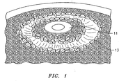
- FIG. 1 is a photograph of an exemplary combination of matrix TBC and fugitive material for use in EB-PVD according to the method of the present invention
- FIG. 2 is a photomicrograph of the porosity formed in a 7YSZ coating utilizing a molybdenum fugitive material according to the method of the present invention.
- FIG. 3 is a photomicrograph of the porosity formed in a 7YSZ coating utilizing a carbon fugitive material according to the method of the present invention.
- Like reference numbers and designations in the various drawings indicate like elements.
- It is a teaching of the present invention to provide a method for creating a thermal barrier coating (TBC) with a reduced thermal conductivity resulting from the fabrication of a porous microstructure in the TBC. The porous structure is achieved through the co-evaporation of a fugitive material with the matrix TBC onto a part to be coated. Heat treatment of the co-evaporated deposition results in the liberation of the fugitive phase material leaving behind a porous network structure. The porous structure results in both a lowered thermal conductivity and reduced mass.
- The matrix TBC may consist of any ceramic material that does not interact with the fugitive material in such a way that the fugitive material cannot be removed after deposition of the TBC. Preferred ceramics include carbides, nitrides, silicides, and zirconium based ceramics. In particular, yttria stabilized zirconia (7YSZ) is a widely used matrix TBC which is well suited to the method of the present invention.
- As noted above, the method of the present invention involves the co-evaporation of a "matrix" TBC oxide along with a fugitive material in a predetermined ratio. Subsequent to co-evaporation, a post-coating, alloy friendly, oxidation heat treatment is used to liberate the fugitive material from the coating, leaving a porous structure. By "alloy friendly" it is meant that the maximum temperature at which the heat treatment is performed is below the melting temperature of the alloy from which the coated part is created. Preferably, the maximum temperature at which the heat treatment is performed is below the incipient melting point of any and all portions of the coated part exposed to the heat treatment. For the heat treatment of parts composed of nickel based alloys, maximum heat treatment temperatures typically range from 1750°F (955°C) to 2100°F (1150°C).
- It is required that the fugitive material be predominately stable in the deposition environment but easily removed (i.e. unstable) following the coating deposition step. The fugitive material must be compatible with the TBC oxide and the very high processing temperatures typical of EB-PVD coatings. By "compatible" it is meant that the fugitive material is not such as to alloy or diffuse into the TBC ceramic. While the present invention is therefore broadly drawn to encompass any and all compatible fugitive materials, three materials which form desired volatile decomposition products under typical post-coating heat exposure conditions, namely oxidation at a relatively low temperature in an atmospheric environment, are carbon, molybdenum and tungsten.
- In practice, both the matrix TBC and the fugitive material are deposited in layers upon the part to be coated. The matrix TBC and the fugitive material are deposited through a process of electron beam physical vapor deposition (EB-PVD). Various methods may be employed to achieve the deposition of the matrix TBC and the fugitive material in desired proportions. In one embodiment, particulate ceramic and a solid piece of fugitive material is utilized. Such an exemplary configuration is illustrated with reference to Fig. 1.
Molybdenum disk 11 is surrounded, post EB-PVD, by solidified 7YSZ. During evaporation, an electron beam is directed in alternating fashion at theMolybdenum disk 11 and the particulate 7YSZ. - In another embodiment, preformed ingots of the matrix TBC and the fugitive material are utilized as the source of the coating vapor.
- As a result of the method described above, multiple layers of a matrix TBC oxide and at least one fugitive material can be deposited upon a part. Each individual layer contains a different percentage mixture of fugitive material resulting in a predetermined post-heating porosity. In one embodiment, there is alternatingly deposited upon the part at least one layer containing a fugitive material and at least one layer containing no fugitive material. As a result, post heat treatment, there exists at least one layer of the resulting TBC of a density undiminished by the liberation of a fugitive material.
- The amount of porosity within a layer is controllable based on the ratio of fugitive to matrix material evaporated in the co-evaporation step. Microstructures, such as continuously porous or graded porosity coatings can be produced. To produce graded porosity coatings, multi-source EB-PVD is performed whereby the intensity of the electron beam used to vaporize the fugitive material is varied in accordance with the desired amount of gradation. When employing a dual-or multi-source coating process, the initial and final layers of the deposited TBC may be of higher density or different composition than the matrix TBC (depending on the number of evaporation sources employed) to further enhance the characteristics of the TBC system. For example, selection of different material layers to optimize oxidation resistance, TBC adherence and erosion/impact resistance is possible. Such material layers may consist of, but are not limited to, yttria-stabilized zirconia or alumina.
- Example: EB-PVD of 7YSZ as the matrix TBC oxide with either Carbon or Molybdenum as fugitives materials was successfully deposited in a layer upon a part made of a nickel-based alloy. Both materials proved sufficiently stable during the EB-PVD process environment to function in the desired manner. That is, they were co-evaporated, deposited and subsequently, removed (2050F/4 hour/air post-coat heat treatment) to produce a pore structure having a 27% volume fraction as compared to pure 7YSZ. The thermal conductivity was measured to be 1.1 W/m°C.
- With reference to Figure 1 there is illustrated the crucible configuration utilized to evaluate the EB-PVD fugitive phase process. The basic approach is the same for any of the above candidate fugitive materials. In the photograph, the molybdenum disc is located at the center of the crucible, surrounded by the ceramic particulate. The 7YSZ and fugitive materials are co-evaporated by manipulation of the electron beam. Alternating layers, of "dense" and "porous" TBC were evaporated. In addition, a coating deposition program was followed to provide initial and final application of dense (ie. "substantially pure") 7YSZ, to promote TBC adherence and erosion resistance. Furthermore, the deposition program was modified to produce both a "continuous" and a "graded" porosity as described above.
- Figures 2 and 3 are SEM photomicrographs illustrating the type of 7YSZ coating microstructures achieved with molybdenum and carbon fugitives, respectively. As is visually apparent, the width of the individual pores formed using either fugitive is approximately between 10-100 nanometers. While individual pores measure approximately 10-100 nanometers in diameter, the total reduction in mass of the matrix TBC per unit volume was shown to range from 5% to 40%.
- While a greater percentage reduction in the mass of the matrix TBC resulting from porosity results in greater reductions in thermal conductivity, there must be balanced a concern for the weakened physical properties of the TBC arising from the removal of fugitive materials. It is therefore preferred that a fugitive material be employed to provide an approximate pore size of between 10-100 nanometers in an amount sufficient to result, post liberation, in the removal of no more than 70% by weight of the matrix TBC. While a 100% evacuation of the fugitive material form the co-evaporated combination of the fugitive material and the matrix TBC is preferred, it is sufficient that at least 90% of the fugitive material is liberated and removed from the TBC.
Claims (15)
- A method of reducing thermal conductivity in thermal barrier coatings (TBC) which are deposited via an electron beam physical vapor deposition process (EB-PVD) through the incorporation of porosity comprising the steps of:building up a thermal barrier coating by depositing alternating layers of thermal barrier material upon a part by EBPVD, the deposition process comprising alternatingly depositing:a mixture comprising a TBC matrix and a first percentage of fugitive material upon the part to form first layers; anda TBC matrix and a second different percentage of fugitive material upon the part to form second layers,whereby multiple alternate layers of mixture of a matrix TBC and a fugitive material are deposited upon the part, andheating said layers at a temperature and for a duration sufficient to liberate a portion of said fugitive material to form a porous network.
- The method of claim 1 wherein the second layers are free of fugitive material.
- The method of claim 1 or 2 wherein said depositing said TBC matrix comprises depositing a ceramic selected from the group consisting of 7YSZ, carbides, nitrides, silicides, and zirconium based ceramics.
- The method of claim 1, 2 or 3 wherein said depositing said fugitive material comprises depositing a fugitive material selected from the group comprising carbon, molybdenum and tungsten.
- The method of any preceding claim wherein said depositing said mixture via EB-PVD comprises utilizing particulate TBC matrix and particulate fugitive material.
- The method of any of claims 1 to 4 wherein said depositing said mixture via EB-PVD comprises utilizing an ingot of said TBC matrix and an ingot of said fugitive material.
- The method of claim 5 or 6 wherein the mixture is deposited by co-evaporating the TBC matrix and fugitive materials through directing the electron beam in an alternating fashion at the materials.
- The method of any preceding claim wherein said heating comprises heating said layers to a temperature less than the melting temperature of the part.
- The method of any of claims 1 to 7 wherein said heating comprises heating said layers to a temperature less than the incipient melting point of the part.
- The method of any of claims 1 to 7 wherein said heating comprises heating said layers to a temperature between approximately 1750°F (955°C) and 2100°F (1150°C).
- The method of any of claims 1 to 7 wherein said heating comprises heating said layers to a temperature and for a duration sufficient to liberate at least 90% of said fugitive material.
- The method of any preceding claim wherein said depositing said mixture comprises the steps of altering the rate at which said TBC matrix and said fugitive material is deposited to form said first layers and heating said layers to produce a layer having a gradation of porosity.
- The method of any preceding claim wherein said heating comprises heating said layers to produce said porous network comprising a volume not greater than 40% of said layer by volume.
- The method of any preceding claim wherein said porous network is comprised of a plurality of pores each having a width between ten and one hundred nanometers.
- The method of any preceding claim wherein said depositing step comprises depositing said mixture upon a gas turbine engine component.
Applications Claiming Priority (2)
| Application Number | Priority Date | Filing Date | Title |
|---|---|---|---|
| US10/805,922 US20050208337A1 (en) | 2004-03-22 | 2004-03-22 | Reduced thermal conductivity TBC by EB-PVD process to incorporate porosity |
| US805922 | 2004-03-22 |
Publications (3)
| Publication Number | Publication Date |
|---|---|
| EP1580296A2 EP1580296A2 (en) | 2005-09-28 |
| EP1580296A3 EP1580296A3 (en) | 2005-10-05 |
| EP1580296B1 true EP1580296B1 (en) | 2008-01-02 |
Family
ID=34862025
Family Applications (1)
| Application Number | Title | Priority Date | Filing Date |
|---|---|---|---|
| EP20050251745 Expired - Lifetime EP1580296B1 (en) | 2004-03-22 | 2005-03-22 | Reduced thermal conductivity TBC by EB-PVD process to incorporate porosity |
Country Status (5)
| Country | Link |
|---|---|
| US (1) | US20050208337A1 (en) |
| EP (1) | EP1580296B1 (en) |
| JP (1) | JP2005273017A (en) |
| AT (1) | ATE382720T1 (en) |
| DE (1) | DE602005004055T2 (en) |
Families Citing this family (7)
| Publication number | Priority date | Publication date | Assignee | Title |
|---|---|---|---|---|
| US6983718B1 (en) * | 1999-08-04 | 2006-01-10 | General Electric Company | Electron beam physical vapor deposition apparatus |
| SG128580A1 (en) * | 2005-06-08 | 2007-01-30 | United Technologies Corp | Reduced thermal conductivity thermal barrier coating by electron beam-physical vapor deposition process |
| DE102014018693A1 (en) | 2014-12-18 | 2016-06-23 | Mahle International Gmbh | Method for producing a thermal barrier coating and thermal barrier coating produced by this method |
| US9657387B1 (en) * | 2016-04-28 | 2017-05-23 | General Electric Company | Methods of forming a multilayer thermal barrier coating system |
| US20190169730A1 (en) * | 2017-12-04 | 2019-06-06 | General Electric Company | Methods of forming a porous thermal barrier coating |
| CN110042371B (en) * | 2019-05-24 | 2023-10-20 | 北京化工大学 | Device and method for preparing porous thermal barrier coating by adopting low-temperature plasma |
| CN115637402B (en) * | 2022-11-07 | 2023-09-01 | 哈尔滨工业大学 | Method for preparing high-temperature-resistant abradable seal coating with multistage holes or gradient holes based on electrostatic field auxiliary item conversion |
Family Cites Families (9)
| Publication number | Priority date | Publication date | Assignee | Title |
|---|---|---|---|---|
| US5512382A (en) * | 1995-05-08 | 1996-04-30 | Alliedsignal Inc. | Porous thermal barrier coating |
| US5824423A (en) * | 1996-02-07 | 1998-10-20 | N.V. Interturbine | Thermal barrier coating system and methods |
| US6946208B2 (en) * | 1996-12-10 | 2005-09-20 | Siemens Westinghouse Power Corporation | Sinter resistant abradable thermal barrier coating |
| US6835465B2 (en) * | 1996-12-10 | 2004-12-28 | Siemens Westinghouse Power Corporation | Thermal barrier layer and process for producing the same |
| UA74150C2 (en) * | 2002-01-09 | 2005-11-15 | Дженерал Електрік Компані | method fOR formING thermal barrier coating (VARIANTS) and thermal barrier coating |
| US6998172B2 (en) * | 2002-01-09 | 2006-02-14 | General Electric Company | Thermally-stabilized thermal barrier coating |
| WO2004043691A1 (en) * | 2002-11-12 | 2004-05-27 | University Of Virginia Patent Foundation | Extremely strain tolerant thermal protection coating and related method and apparatus thereof |
| US7150921B2 (en) * | 2004-05-18 | 2006-12-19 | General Electric Company | Bi-layer HVOF coating with controlled porosity for use in thermal barrier coatings |
| US20070116883A1 (en) * | 2005-11-22 | 2007-05-24 | General Electric Company | Process for forming thermal barrier coating resistant to infiltration |
-
2004
- 2004-03-22 US US10/805,922 patent/US20050208337A1/en not_active Abandoned
-
2005
- 2005-03-18 JP JP2005078757A patent/JP2005273017A/en not_active Ceased
- 2005-03-22 DE DE200560004055 patent/DE602005004055T2/en not_active Expired - Lifetime
- 2005-03-22 AT AT05251745T patent/ATE382720T1/en not_active IP Right Cessation
- 2005-03-22 EP EP20050251745 patent/EP1580296B1/en not_active Expired - Lifetime
Also Published As
| Publication number | Publication date |
|---|---|
| DE602005004055D1 (en) | 2008-02-14 |
| EP1580296A3 (en) | 2005-10-05 |
| US20050208337A1 (en) | 2005-09-22 |
| JP2005273017A (en) | 2005-10-06 |
| DE602005004055T2 (en) | 2008-12-18 |
| EP1580296A2 (en) | 2005-09-28 |
| ATE382720T1 (en) | 2008-01-15 |
Similar Documents
| Publication | Publication Date | Title |
|---|---|---|
| EP1111085B1 (en) | Method for producing ceramic coatings | |
| US6057047A (en) | Ceramic coatings containing layered porosity | |
| EP1335040B1 (en) | Method of forming a coating resistant to deposits | |
| EP0780484B1 (en) | Thermal barrier coated articles and method for coating | |
| US5683761A (en) | Alpha alumina protective coatings for bond-coated substrates and their preparation | |
| US8100083B2 (en) | Process and apparatus for depositing a ceramic coating | |
| KR20030068054A (en) | Hybrid thermal barrier coating and method of making the same | |
| JP2007277722A (en) | Process for applying coating, bond coat composition, and coated article | |
| JP6386740B2 (en) | Ceramic powder and method therefor | |
| KR20070067607A (en) | High Strength Ni-Plat-Al-Hf Bond Coating | |
| Movchan et al. | High-temperature protective coatings produced by EB-PVD | |
| EP1580296B1 (en) | Reduced thermal conductivity TBC by EB-PVD process to incorporate porosity | |
| JP2005281865A (en) | Method for protecting article, and related composition | |
| Najafizadeh et al. | Thermal barrier ceramic coatings | |
| US8147928B2 (en) | Reduced thermal conductivity thermal barrier coating by electron beam-physical vapor deposition process | |
| EP1400607B1 (en) | Thermal barrier coating with improved strength and fracture toughness | |
| UA78487C2 (en) | Method for application of ceramic covering and device for realization the same | |
| US6521053B1 (en) | In-situ formation of a protective coating on a substrate | |
| KR102156836B1 (en) | Method for preparing superalloy composites with improved high temperature oxidation resistance | |
| Nicholls et al. | Vapour phase alloy design of corrosion-resistant overlay coatings | |
| Romanowska et al. | Zirconium modified aluminide coatings obtained by the CVD and PVD methods | |
| Li | Cyclic and Isothermal Oxidation Resistance of ASPS Thermal Barrier Coating Systems | |
| JPH11264082A (en) | Heat resistant member and method of manufacturing heat resistant member | |
| Saint-Ramond | Low-mass platinum aluminide bondcoat for thermal barrier coating |
Legal Events
| Date | Code | Title | Description |
|---|---|---|---|
| PUAI | Public reference made under article 153(3) epc to a published international application that has entered the european phase |
Free format text: ORIGINAL CODE: 0009012 |
|
| PUAL | Search report despatched |
Free format text: ORIGINAL CODE: 0009013 |
|
| AK | Designated contracting states |
Kind code of ref document: A2 Designated state(s): AT BE BG CH CY CZ DE DK EE ES FI FR GB GR HU IE IS IT LI LT LU MC NL PL PT RO SE SI SK TR |
|
| AX | Request for extension of the european patent |
Extension state: AL BA HR LV MK YU |
|
| AK | Designated contracting states |
Kind code of ref document: A3 Designated state(s): AT BE BG CH CY CZ DE DK EE ES FI FR GB GR HU IE IS IT LI LT LU MC NL PL PT RO SE SI SK TR |
|
| AX | Request for extension of the european patent |
Extension state: AL BA HR LV MK YU |
|
| 17P | Request for examination filed |
Effective date: 20051221 |
|
| AKX | Designation fees paid |
Designated state(s): AT BE BG CH CY CZ DE DK EE ES FI FR GB GR HU IE IS IT LI LT LU MC NL PL PT RO SE SI SK TR |
|
| GRAP | Despatch of communication of intention to grant a patent |
Free format text: ORIGINAL CODE: EPIDOSNIGR1 |
|
| GRAS | Grant fee paid |
Free format text: ORIGINAL CODE: EPIDOSNIGR3 |
|
| GRAA | (expected) grant |
Free format text: ORIGINAL CODE: 0009210 |
|
| AK | Designated contracting states |
Kind code of ref document: B1 Designated state(s): AT BE BG CH CY CZ DE DK EE ES FI FR GB GR HU IE IS IT LI LT LU MC NL PL PT RO SE SI SK TR |
|
| REG | Reference to a national code |
Ref country code: GB Ref legal event code: FG4D |
|
| REG | Reference to a national code |
Ref country code: IE Ref legal event code: FG4D |
|
| REG | Reference to a national code |
Ref country code: CH Ref legal event code: EP |
|
| REF | Corresponds to: |
Ref document number: 602005004055 Country of ref document: DE Date of ref document: 20080214 Kind code of ref document: P |
|
| PG25 | Lapsed in a contracting state [announced via postgrant information from national office to epo] |
Ref country code: SI Free format text: LAPSE BECAUSE OF FAILURE TO SUBMIT A TRANSLATION OF THE DESCRIPTION OR TO PAY THE FEE WITHIN THE PRESCRIBED TIME-LIMIT Effective date: 20080102 |
|
| PG25 | Lapsed in a contracting state [announced via postgrant information from national office to epo] |
Ref country code: LI Free format text: LAPSE BECAUSE OF FAILURE TO SUBMIT A TRANSLATION OF THE DESCRIPTION OR TO PAY THE FEE WITHIN THE PRESCRIBED TIME-LIMIT Effective date: 20080102 Ref country code: IS Free format text: LAPSE BECAUSE OF FAILURE TO SUBMIT A TRANSLATION OF THE DESCRIPTION OR TO PAY THE FEE WITHIN THE PRESCRIBED TIME-LIMIT Effective date: 20080502 Ref country code: CH Free format text: LAPSE BECAUSE OF FAILURE TO SUBMIT A TRANSLATION OF THE DESCRIPTION OR TO PAY THE FEE WITHIN THE PRESCRIBED TIME-LIMIT Effective date: 20080102 Ref country code: ES Free format text: LAPSE BECAUSE OF FAILURE TO SUBMIT A TRANSLATION OF THE DESCRIPTION OR TO PAY THE FEE WITHIN THE PRESCRIBED TIME-LIMIT Effective date: 20080413 Ref country code: FI Free format text: LAPSE BECAUSE OF FAILURE TO SUBMIT A TRANSLATION OF THE DESCRIPTION OR TO PAY THE FEE WITHIN THE PRESCRIBED TIME-LIMIT Effective date: 20080102 Ref country code: LT Free format text: LAPSE BECAUSE OF FAILURE TO SUBMIT A TRANSLATION OF THE DESCRIPTION OR TO PAY THE FEE WITHIN THE PRESCRIBED TIME-LIMIT Effective date: 20080102 |
|
| REG | Reference to a national code |
Ref country code: CH Ref legal event code: PL |
|
| PG25 | Lapsed in a contracting state [announced via postgrant information from national office to epo] |
Ref country code: AT Free format text: LAPSE BECAUSE OF FAILURE TO SUBMIT A TRANSLATION OF THE DESCRIPTION OR TO PAY THE FEE WITHIN THE PRESCRIBED TIME-LIMIT Effective date: 20080102 Ref country code: BG Free format text: LAPSE BECAUSE OF FAILURE TO SUBMIT A TRANSLATION OF THE DESCRIPTION OR TO PAY THE FEE WITHIN THE PRESCRIBED TIME-LIMIT Effective date: 20080402 |
|
| PG25 | Lapsed in a contracting state [announced via postgrant information from national office to epo] |
Ref country code: PL Free format text: LAPSE BECAUSE OF FAILURE TO SUBMIT A TRANSLATION OF THE DESCRIPTION OR TO PAY THE FEE WITHIN THE PRESCRIBED TIME-LIMIT Effective date: 20080102 Ref country code: BE Free format text: LAPSE BECAUSE OF FAILURE TO SUBMIT A TRANSLATION OF THE DESCRIPTION OR TO PAY THE FEE WITHIN THE PRESCRIBED TIME-LIMIT Effective date: 20080102 Ref country code: PT Free format text: LAPSE BECAUSE OF FAILURE TO SUBMIT A TRANSLATION OF THE DESCRIPTION OR TO PAY THE FEE WITHIN THE PRESCRIBED TIME-LIMIT Effective date: 20080602 |
|
| EN | Fr: translation not filed | ||
| PG25 | Lapsed in a contracting state [announced via postgrant information from national office to epo] |
Ref country code: DK Free format text: LAPSE BECAUSE OF FAILURE TO SUBMIT A TRANSLATION OF THE DESCRIPTION OR TO PAY THE FEE WITHIN THE PRESCRIBED TIME-LIMIT Effective date: 20080102 Ref country code: MC Free format text: LAPSE BECAUSE OF NON-PAYMENT OF DUE FEES Effective date: 20080331 Ref country code: CZ Free format text: LAPSE BECAUSE OF FAILURE TO SUBMIT A TRANSLATION OF THE DESCRIPTION OR TO PAY THE FEE WITHIN THE PRESCRIBED TIME-LIMIT Effective date: 20080102 Ref country code: SE Free format text: LAPSE BECAUSE OF FAILURE TO SUBMIT A TRANSLATION OF THE DESCRIPTION OR TO PAY THE FEE WITHIN THE PRESCRIBED TIME-LIMIT Effective date: 20080402 Ref country code: SK Free format text: LAPSE BECAUSE OF FAILURE TO SUBMIT A TRANSLATION OF THE DESCRIPTION OR TO PAY THE FEE WITHIN THE PRESCRIBED TIME-LIMIT Effective date: 20080102 |
|
| PLBE | No opposition filed within time limit |
Free format text: ORIGINAL CODE: 0009261 |
|
| STAA | Information on the status of an ep patent application or granted ep patent |
Free format text: STATUS: NO OPPOSITION FILED WITHIN TIME LIMIT |
|
| PG25 | Lapsed in a contracting state [announced via postgrant information from national office to epo] |
Ref country code: RO Free format text: LAPSE BECAUSE OF FAILURE TO SUBMIT A TRANSLATION OF THE DESCRIPTION OR TO PAY THE FEE WITHIN THE PRESCRIBED TIME-LIMIT Effective date: 20080102 |
|
| 26N | No opposition filed |
Effective date: 20081003 |
|
| PG25 | Lapsed in a contracting state [announced via postgrant information from national office to epo] |
Ref country code: EE Free format text: LAPSE BECAUSE OF FAILURE TO SUBMIT A TRANSLATION OF THE DESCRIPTION OR TO PAY THE FEE WITHIN THE PRESCRIBED TIME-LIMIT Effective date: 20080102 Ref country code: IE Free format text: LAPSE BECAUSE OF NON-PAYMENT OF DUE FEES Effective date: 20080324 |
|
| PG25 | Lapsed in a contracting state [announced via postgrant information from national office to epo] |
Ref country code: FR Free format text: LAPSE BECAUSE OF FAILURE TO SUBMIT A TRANSLATION OF THE DESCRIPTION OR TO PAY THE FEE WITHIN THE PRESCRIBED TIME-LIMIT Effective date: 20081024 |
|
| PG25 | Lapsed in a contracting state [announced via postgrant information from national office to epo] |
Ref country code: CY Free format text: LAPSE BECAUSE OF FAILURE TO SUBMIT A TRANSLATION OF THE DESCRIPTION OR TO PAY THE FEE WITHIN THE PRESCRIBED TIME-LIMIT Effective date: 20080102 |
|
| PG25 | Lapsed in a contracting state [announced via postgrant information from national office to epo] |
Ref country code: IT Free format text: LAPSE BECAUSE OF FAILURE TO SUBMIT A TRANSLATION OF THE DESCRIPTION OR TO PAY THE FEE WITHIN THE PRESCRIBED TIME-LIMIT Effective date: 20080102 |
|
| NLV4 | Nl: lapsed or anulled due to non-payment of the annual fee |
Effective date: 20091001 |
|
| PG25 | Lapsed in a contracting state [announced via postgrant information from national office to epo] |
Ref country code: NL Free format text: LAPSE BECAUSE OF NON-PAYMENT OF DUE FEES Effective date: 20091001 |
|
| PG25 | Lapsed in a contracting state [announced via postgrant information from national office to epo] |
Ref country code: LU Free format text: LAPSE BECAUSE OF NON-PAYMENT OF DUE FEES Effective date: 20080322 Ref country code: HU Free format text: LAPSE BECAUSE OF FAILURE TO SUBMIT A TRANSLATION OF THE DESCRIPTION OR TO PAY THE FEE WITHIN THE PRESCRIBED TIME-LIMIT Effective date: 20080703 |
|
| PG25 | Lapsed in a contracting state [announced via postgrant information from national office to epo] |
Ref country code: TR Free format text: LAPSE BECAUSE OF FAILURE TO SUBMIT A TRANSLATION OF THE DESCRIPTION OR TO PAY THE FEE WITHIN THE PRESCRIBED TIME-LIMIT Effective date: 20080102 |
|
| PG25 | Lapsed in a contracting state [announced via postgrant information from national office to epo] |
Ref country code: GR Free format text: LAPSE BECAUSE OF FAILURE TO SUBMIT A TRANSLATION OF THE DESCRIPTION OR TO PAY THE FEE WITHIN THE PRESCRIBED TIME-LIMIT Effective date: 20080403 |
|
| REG | Reference to a national code |
Ref country code: DE Ref legal event code: R082 Ref document number: 602005004055 Country of ref document: DE Representative=s name: SCHMITT-NILSON SCHRAUD WAIBEL WOHLFROM PATENTA, DE |
|
| REG | Reference to a national code |
Ref country code: DE Ref legal event code: R082 Ref document number: 602005004055 Country of ref document: DE Representative=s name: SCHMITT-NILSON SCHRAUD WAIBEL WOHLFROM PATENTA, DE Ref country code: DE Ref legal event code: R081 Ref document number: 602005004055 Country of ref document: DE Owner name: UNITED TECHNOLOGIES CORP. (N.D.GES.D. STAATES , US Free format text: FORMER OWNER: UNITED TECHNOLOGIES CORPORATION, HARTFORD, CONN., US |
|
| PGFP | Annual fee paid to national office [announced via postgrant information from national office to epo] |
Ref country code: DE Payment date: 20220217 Year of fee payment: 18 |
|
| REG | Reference to a national code |
Ref country code: DE Ref legal event code: R081 Ref document number: 602005004055 Country of ref document: DE Owner name: RAYTHEON TECHNOLOGIES CORPORATION (N.D.GES.D.S, US Free format text: FORMER OWNER: UNITED TECHNOLOGIES CORP. (N.D.GES.D. STAATES DELAWARE), FARMINGTON, CONN., US |
|
| REG | Reference to a national code |
Ref country code: DE Ref legal event code: R119 Ref document number: 602005004055 Country of ref document: DE |
|
| PG25 | Lapsed in a contracting state [announced via postgrant information from national office to epo] |
Ref country code: DE Free format text: LAPSE BECAUSE OF NON-PAYMENT OF DUE FEES Effective date: 20231003 |
|
| PGFP | Annual fee paid to national office [announced via postgrant information from national office to epo] |
Ref country code: GB Payment date: 20240220 Year of fee payment: 20 |
|
| REG | Reference to a national code |
Ref country code: GB Ref legal event code: PE20 Expiry date: 20250321 |
|
| PG25 | Lapsed in a contracting state [announced via postgrant information from national office to epo] |
Ref country code: GB Free format text: LAPSE BECAUSE OF EXPIRATION OF PROTECTION Effective date: 20250321 |