EP1580293A2 - An article having a vibration damping coating and a method of applying a vibration damping coating to an article - Google Patents
An article having a vibration damping coating and a method of applying a vibration damping coating to an article Download PDFInfo
- Publication number
- EP1580293A2 EP1580293A2 EP05251207A EP05251207A EP1580293A2 EP 1580293 A2 EP1580293 A2 EP 1580293A2 EP 05251207 A EP05251207 A EP 05251207A EP 05251207 A EP05251207 A EP 05251207A EP 1580293 A2 EP1580293 A2 EP 1580293A2
- Authority
- EP
- European Patent Office
- Prior art keywords
- vibration damping
- damping coating
- erosion resistant
- resistant material
- article
- Prior art date
- Legal status (The legal status is an assumption and is not a legal conclusion. Google has not performed a legal analysis and makes no representation as to the accuracy of the status listed.)
- Granted
Links
Images
Classifications
-
- C—CHEMISTRY; METALLURGY
- C23—COATING METALLIC MATERIAL; COATING MATERIAL WITH METALLIC MATERIAL; CHEMICAL SURFACE TREATMENT; DIFFUSION TREATMENT OF METALLIC MATERIAL; COATING BY VACUUM EVAPORATION, BY SPUTTERING, BY ION IMPLANTATION OR BY CHEMICAL VAPOUR DEPOSITION, IN GENERAL; INHIBITING CORROSION OF METALLIC MATERIAL OR INCRUSTATION IN GENERAL
- C23C—COATING METALLIC MATERIAL; COATING MATERIAL WITH METALLIC MATERIAL; SURFACE TREATMENT OF METALLIC MATERIAL BY DIFFUSION INTO THE SURFACE, BY CHEMICAL CONVERSION OR SUBSTITUTION; COATING BY VACUUM EVAPORATION, BY SPUTTERING, BY ION IMPLANTATION OR BY CHEMICAL VAPOUR DEPOSITION, IN GENERAL
- C23C4/00—Coating by spraying the coating material in the molten state, e.g. by flame, plasma or electric discharge
- C23C4/02—Pretreatment of the material to be coated, e.g. for coating on selected surface areas
-
- C—CHEMISTRY; METALLURGY
- C23—COATING METALLIC MATERIAL; COATING MATERIAL WITH METALLIC MATERIAL; CHEMICAL SURFACE TREATMENT; DIFFUSION TREATMENT OF METALLIC MATERIAL; COATING BY VACUUM EVAPORATION, BY SPUTTERING, BY ION IMPLANTATION OR BY CHEMICAL VAPOUR DEPOSITION, IN GENERAL; INHIBITING CORROSION OF METALLIC MATERIAL OR INCRUSTATION IN GENERAL
- C23C—COATING METALLIC MATERIAL; COATING MATERIAL WITH METALLIC MATERIAL; SURFACE TREATMENT OF METALLIC MATERIAL BY DIFFUSION INTO THE SURFACE, BY CHEMICAL CONVERSION OR SUBSTITUTION; COATING BY VACUUM EVAPORATION, BY SPUTTERING, BY ION IMPLANTATION OR BY CHEMICAL VAPOUR DEPOSITION, IN GENERAL
- C23C28/00—Coating for obtaining at least two superposed coatings either by methods not provided for in a single one of groups C23C2/00 - C23C26/00 or by combinations of methods provided for in subclasses C23C and C25C or C25D
- C23C28/04—Coating for obtaining at least two superposed coatings either by methods not provided for in a single one of groups C23C2/00 - C23C26/00 or by combinations of methods provided for in subclasses C23C and C25C or C25D only coatings of inorganic non-metallic material
- C23C28/042—Coating for obtaining at least two superposed coatings either by methods not provided for in a single one of groups C23C2/00 - C23C26/00 or by combinations of methods provided for in subclasses C23C and C25C or C25D only coatings of inorganic non-metallic material including a refractory ceramic layer, e.g. refractory metal oxides, ZrO2, rare earth oxides
-
- C—CHEMISTRY; METALLURGY
- C23—COATING METALLIC MATERIAL; COATING MATERIAL WITH METALLIC MATERIAL; CHEMICAL SURFACE TREATMENT; DIFFUSION TREATMENT OF METALLIC MATERIAL; COATING BY VACUUM EVAPORATION, BY SPUTTERING, BY ION IMPLANTATION OR BY CHEMICAL VAPOUR DEPOSITION, IN GENERAL; INHIBITING CORROSION OF METALLIC MATERIAL OR INCRUSTATION IN GENERAL
- C23C—COATING METALLIC MATERIAL; COATING MATERIAL WITH METALLIC MATERIAL; SURFACE TREATMENT OF METALLIC MATERIAL BY DIFFUSION INTO THE SURFACE, BY CHEMICAL CONVERSION OR SUBSTITUTION; COATING BY VACUUM EVAPORATION, BY SPUTTERING, BY ION IMPLANTATION OR BY CHEMICAL VAPOUR DEPOSITION, IN GENERAL
- C23C4/00—Coating by spraying the coating material in the molten state, e.g. by flame, plasma or electric discharge
- C23C4/01—Selective coating, e.g. pattern coating, without pre-treatment of the material to be coated
-
- C—CHEMISTRY; METALLURGY
- C23—COATING METALLIC MATERIAL; COATING MATERIAL WITH METALLIC MATERIAL; CHEMICAL SURFACE TREATMENT; DIFFUSION TREATMENT OF METALLIC MATERIAL; COATING BY VACUUM EVAPORATION, BY SPUTTERING, BY ION IMPLANTATION OR BY CHEMICAL VAPOUR DEPOSITION, IN GENERAL; INHIBITING CORROSION OF METALLIC MATERIAL OR INCRUSTATION IN GENERAL
- C23C—COATING METALLIC MATERIAL; COATING MATERIAL WITH METALLIC MATERIAL; SURFACE TREATMENT OF METALLIC MATERIAL BY DIFFUSION INTO THE SURFACE, BY CHEMICAL CONVERSION OR SUBSTITUTION; COATING BY VACUUM EVAPORATION, BY SPUTTERING, BY ION IMPLANTATION OR BY CHEMICAL VAPOUR DEPOSITION, IN GENERAL
- C23C4/00—Coating by spraying the coating material in the molten state, e.g. by flame, plasma or electric discharge
- C23C4/18—After-treatment
-
- Y—GENERAL TAGGING OF NEW TECHNOLOGICAL DEVELOPMENTS; GENERAL TAGGING OF CROSS-SECTIONAL TECHNOLOGIES SPANNING OVER SEVERAL SECTIONS OF THE IPC; TECHNICAL SUBJECTS COVERED BY FORMER USPC CROSS-REFERENCE ART COLLECTIONS [XRACs] AND DIGESTS
- Y10—TECHNICAL SUBJECTS COVERED BY FORMER USPC
- Y10S—TECHNICAL SUBJECTS COVERED BY FORMER USPC CROSS-REFERENCE ART COLLECTIONS [XRACs] AND DIGESTS
- Y10S416/00—Fluid reaction surfaces, i.e. impellers
- Y10S416/50—Vibration damping features
-
- Y—GENERAL TAGGING OF NEW TECHNOLOGICAL DEVELOPMENTS; GENERAL TAGGING OF CROSS-SECTIONAL TECHNOLOGIES SPANNING OVER SEVERAL SECTIONS OF THE IPC; TECHNICAL SUBJECTS COVERED BY FORMER USPC CROSS-REFERENCE ART COLLECTIONS [XRACs] AND DIGESTS
- Y10—TECHNICAL SUBJECTS COVERED BY FORMER USPC
- Y10T—TECHNICAL SUBJECTS COVERED BY FORMER US CLASSIFICATION
- Y10T156/00—Adhesive bonding and miscellaneous chemical manufacture
- Y10T156/10—Methods of surface bonding and/or assembly therefor
- Y10T156/1002—Methods of surface bonding and/or assembly therefor with permanent bending or reshaping or surface deformation of self sustaining lamina
- Y10T156/1028—Methods of surface bonding and/or assembly therefor with permanent bending or reshaping or surface deformation of self sustaining lamina by bending, drawing or stretch forming sheet to assume shape of configured lamina while in contact therewith
-
- Y—GENERAL TAGGING OF NEW TECHNOLOGICAL DEVELOPMENTS; GENERAL TAGGING OF CROSS-SECTIONAL TECHNOLOGIES SPANNING OVER SEVERAL SECTIONS OF THE IPC; TECHNICAL SUBJECTS COVERED BY FORMER USPC CROSS-REFERENCE ART COLLECTIONS [XRACs] AND DIGESTS
- Y10—TECHNICAL SUBJECTS COVERED BY FORMER USPC
- Y10T—TECHNICAL SUBJECTS COVERED BY FORMER US CLASSIFICATION
- Y10T428/00—Stock material or miscellaneous articles
- Y10T428/24—Structurally defined web or sheet [e.g., overall dimension, etc.]
- Y10T428/24149—Honeycomb-like
-
- Y—GENERAL TAGGING OF NEW TECHNOLOGICAL DEVELOPMENTS; GENERAL TAGGING OF CROSS-SECTIONAL TECHNOLOGIES SPANNING OVER SEVERAL SECTIONS OF THE IPC; TECHNICAL SUBJECTS COVERED BY FORMER USPC CROSS-REFERENCE ART COLLECTIONS [XRACs] AND DIGESTS
- Y10—TECHNICAL SUBJECTS COVERED BY FORMER USPC
- Y10T—TECHNICAL SUBJECTS COVERED BY FORMER US CLASSIFICATION
- Y10T428/00—Stock material or miscellaneous articles
- Y10T428/249921—Web or sheet containing structurally defined element or component
- Y10T428/249953—Composite having voids in a component [e.g., porous, cellular, etc.]
Definitions
- the present invention relates to an article having a vibration damping coating and a method of applying a vibration damping coating to an article.
- the present invention relates to a vibration damping coating for a fan blade, a compressor blade, a compressor vane, a turbine blade or a turbine vane of a gas turbine engine.
- Gas turbine engine components for example blades or vanes, may suffer from modes of vibration in operation, which result in a deterioration of the mechanical properties of the gas turbine engine component. Strengthening of the blades or vanes to combat these modes of vibration may require a major redesign of the blades or vanes.
- vibration damping coatings comprise ceramic materials and they are applied by plasma, or thermal, spraying as described in published UK patent application GB2346415A, UK patent GB1369558 and US patent US6059533.
- a problem for some articles for example a disc with integral blades also known as a blisk, is that it is difficult to apply these ceramic coatings because plasma, or thermal, spraying is a line of sight process and therefore access to some regions of the blades is difficult or prevented.
- the present invention seeks to provide a novel vibration damping coating on an article and a novel method of applying a vibration damping coating to an article.
- the present invention provides a method of applying a vibration damping coating to an article comprising the steps of:
- step (a) comprises depositing a vibration damping material onto a first surface of a plurality of portions of an erosion resistant material, the vibration damping coating on each portion of erosion resistant material comprises a plurality of segments and step (b) comprises adhesively bonding the portions of erosion resistant material and the vibration damping coating to the article such that the vibration damping coating is between the surface of the article and the portions of erosion resistant material and such that the portions of erosion resistant material are arranged on different regions of the surface of the article.
- step (a) comprises depositing the vibration damping coating by plasma spraying.
- step (a) comprises placing a mesh on the erosion resistant material, subsequently depositing the vibration damping coating and removing the mesh to form the plurality of segments.
- step (a) comprises treating the vibration damping coating during or after deposition of the vibration damping coating to cause the vibration damping coating to form a plurality of segments.
- step (a) the portion of erosion resistant material is flat during the deposition of the vibration damping coating and in step (b) the portion of erosion resistant material is moulded to the shape of the article during the bonding of the portion of the erosion resistant material and the vibration damping coating to the surface of the article.
- the vibration damping coating is impregnated with a polymer material.
- the vibration damping coating comprises a ceramic.
- the vibration damping coating comprises magnesium aluminate, calcium silicate, zirconia or yttria stabilised zirconia.
- the erosion resistant material comprises a metal.
- the erosion resistant material comprises stainless steel, a nickel alloy or a cobalt alloy.
- the adhesive comprises a structural adhesive.
- the portion of erosion resistant material and vibration damping coating may be heat treated after step (a) and before step (b).
- An erosion resistant coating may be applied to a second surface of the portion of erosion resistant material either before or after step (a).
- the erosion resistant coating may be applied by plasma spraying.
- the article comprises a component of a gas turbine engine.
- the article comprises a fan blade, a compressor blade, a compressor vane, a turbine blade or a turbine vane.
- the article comprises a rotor with integral blades. The blades may be diffusion bonded onto, friction welded onto or machined out of the rotor.
- the present invention also provides an article comprising a vibration damping coating on a first surface of at least one portion of an erosion resistant material, the vibration damping coating comprising a plurality of segments, the portion of erosion resistant material and the vibration damping coating being adhesively bonded to the article such that the vibration damping coating being arranged between the surface of the article and the portion of erosion resistant material.
- the article comprises a vibration damping material on a first surface of a plurality of portions of an erosion resistant material, the vibration damping coating on each portion of erosion resistant material comprising a plurality of segments, the portions of erosion resistant material and the vibration damping coating being adhesively bonded to the article such that the vibration damping coating being arranged between the surface of the article and the portions of erosion resistant material and such that the portions of erosion resistant material being arranged on different regions of the surface of the article.
- the vibration damping coating is impregnated with a polymer material.
- the vibration damping coating comprises a ceramic.
- the vibration damping coating comprises magnesium aluminate, calcium silicate, zirconia or yttria stabilised zirconia.
- the erosion resistant material comprises a metal.
- the erosion resistant material comprises stainless steel, a nickel alloy or a cobalt alloy.
- the adhesive comprises a structural adhesive.
- An erosion resistant coating may be arranged on a second surface of the portion of erosion resistant material.
- the article comprises a component of a gas turbine engine.
- the article comprises a fan blade, a compressor blade, a compressor vane, a turbine blade or a turbine vane.
- the article comprises a rotor with integral blades. The blades may be diffusion bonded onto, friction welded onto or machined out of the rotor.
- a turbofan gas turbine engine 10 as shown in figure 1, comprises in flow series an intake 12, a fan section 14, a compressor section 16, a combustion section 18, a turbine section 20 and an exhaust section 22.
- the turbine section 20 comprises one or more turbines (not shown) arranged to drive a fan (not shown) in the fan section 14 via a shaft (not shown) and one or more turbines (not shown) arranged to drive one or more compressors (not shown) in the compressor section 16 via one or more shafts (not shown).
- the fan, compressors and turbines comprise blades mounted on a fan rotor, a compressor rotor or a turbine rotor respectively.
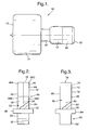
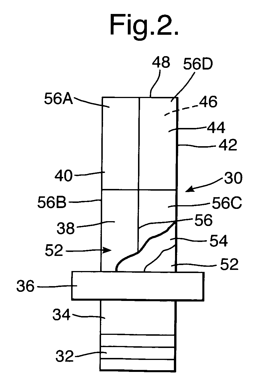
- a compressor blade 30, as shown in figure 2 comprises a root portion 32, a shank portion 34, a platform portion 36 and an aerofoil portion 38.
- the aerofoil portion 38 comprises a leading edge 40, a trailing edge 42, a concave pressure surface 44 which extends form the leading edge 38 to the trailing edge 40 and a convex suction surface 46 which extends from the leading edge 38 to the trailing edge 40 and a radially outer tip 48.
- the aerofoil portion 38 is provided with a vibration damping coating 52 according to the present invention.
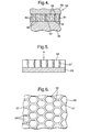
- the vibration damping coating 52 as shown more clearly in figure 4, comprises a vibration damping coating 54 and a portion of an erosion resistant material 56.
- the vibration damping coating 54 is arranged on a first surface of a portion of the erosion resistant material 56.
- the vibration damping coating 54 comprises a plurality of segments 58 separated by gaps 59. In this embodiment the segments 58 are hexagonal, but other suitable shapes may be used.
- the portion of erosion resistant material 56 and the vibration damping coating 54 are adhesively bonded to the aerofoil portion 38 of the compressor blade 30 such that the vibration damping coating 54 is arranged between the surface 50 of the aerofoil portion 38 of the compressor blade 30 and the portion of erosion resistant material 56.
- a compressor rotor 60 with integral blades comprises a rotor disc 62, a rim 64, and a plurality of aerofoil portions 66.
- Each aerofoil portion 66 comprises a leading edge 68, a trailing edge 70, a concave pressure surface 72 which extends form the leading edge 68 to the trailing edge 70 and a convex suction surface 74 which extends from the leading edge 68 to the trailing edge 70 and a radially outer tip 76.
- the aerofoil portions 66 are diffusion bonded onto, friction welded onto or machined out of the rotor 60.
- the aerofoil portions 66 are provided with a vibration damping coating 80 according to the present invention.
- the vibration damping coating 80 is similar to that shown in figure 4, and comprises a vibration damping coating 82 and a portion of an erosion resistant material 84.
- the vibration damping coating 80 is arranged on a first surface of a portion of the erosion resistant material 82.
- the vibration damping coating 80 comprises a plurality of segments separated by gaps. In this embodiment the segments are hexagonal, but other suitable shapes may be used.
- the portion of erosion resistant material 82 and the vibration damping coating 80 are adhesively bonded to the aerofoil portions 68 of the compressor rotor 60 with integral blades such that the vibration damping coating 80 is arranged between the surface 78 of the aerofoil portions 68 of the compressor rotor 60 and the portion of erosion resistant material 84.
- the aerofoil portion 38 of the compressor blade 30 comprises a vibration damping material on a first surface of a plurality of portions 56A, 56B, 56C and 56D of an erosion resistant material 56.
- the vibration damping coating 54 on each portion of erosion resistant material 56A, 56B, 56C and 56D comprises a plurality of segments 58.
- the portions of erosion resistant material 56A, 56B, 56C and 56D and the vibration damping coating 54 are adhesively bonded to the aerofoil portion 38 of the compressor blade 30 such that the vibration damping coating 54 is arranged between the surface 50 of the aerofoil portion 38 of the compressor blade 30 and the portions of erosion resistant material 56A, 56B, 56C and 56D and such that the portions of erosion resistant material 56A, 56B, 56C and 56D are arranged on different regions of the surface 50 of the aerofoil portion 38 of the compressor blade 30.
- the portions 56A, 56B, 56C and 56D of erosion resistant material 56 thus form a plurality of tiles on the surface 50 of the aerofoil portion 38 of the compressor blade 30.
- the vibration damping coating 54 comprises a ceramic and preferably the vibration damping coating 54 comprises magnesium aluminate (magnesia alumina) spinel, e.g. MgO.Al 2 O 3 , calcium silicate, zirconia, e.g. ZrO 2 , or yttria stabilised zirconia, e.g. ZrO 2 8wt% Y 2 O 3 .
- magnesium aluminate (magnesia alumina) spinel e.g. MgO.Al 2 O 3
- calcium silicate zirconia
- zirconia e.g. ZrO 2
- yttria stabilised zirconia e.g. ZrO 2 8wt% Y 2 O 3 .
- the vibration damping coating 54 is preferably impregnated with a polymer material to further increase the vibration damping properties of the vibration damping coating.
- the erosion resistant material preferably comprises a metal, for example stainless steel, a nickel base alloy or a cobalt base alloy.
- the erosion resistant material may comprise a metal foil.
- the adhesive comprises a structural adhesive, for example Henkel Loctite Hysol (RTM) EA9395, supplied by Henkel Loctite, but other suitable structural adhesives may be used.
- RTM Henkel Loctite Hysol
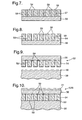
- FIG. 5 to 9 illustrate how the vibration damping coating 52 is applied to the aerofoil portion 38 of the compressor blade 30.
- a portion, or piece, of an erosion resistant material 56 is cut to required the required dimensions and if more than one portion 56A, 56B, 56C and 56D of erosion resistant material 56 is used they are all cut to required dimensions to match and abut against adjacent portions 56A, 56B, 56C and 56D of erosion resistant material 56.
- a mesh, or mask, 57 is arranged on the surface of the portion of erosion resistant material 56 and the mesh, or mask, 57 defines cells 59, as shown in figure 6.
- the mesh, or mask, 57 is hexagonal to define honeycomb cells 59, but other suitable shapes of mesh, mask, 57 may be used.
- the mesh 57 for example comprises a metal.
- a vibration damping coating 54 is plasma sprayed, high velocity oxy fuel sprayed (HVOF) through the mesh, mask, 57 onto the portion of erosion resistant material 56 to form a plurality of segments 58 of vibration damping coating 54 on the portion of erosion resistant material 56 which are separated by the mesh 57, as shown in figure 7.
- HVOF high velocity oxy fuel sprayed
- the mesh 57 is then removed, for example by acid etching, to leave a plurality of segments 58 of vibration damping coating 54 on the portion of erosion resistant material 56, which are separated by gaps 59, as shown in figure 8.
- the portion of erosion resistant material 56 and the vibration damping coating 54 comprising a plurality of discrete separated segments 58 is then adhesively bonded onto the surface 50 of the aerofoil portion 38 of the compressor blade 30 such that the vibration damping coating 54 is arranged between the aerofoil portion 38 of the compressor blade 30 and the erosion resistant material, as shown in figure 9.
- the portion of erosion resistant material 56 in this example comprises a flat foil and thus is flat during the deposition of the vibration damping coating 54.
- the portion of erosion resistant material 56 is moulded to the shape of the aerofoil portion 38 of the compressor blade 30 during the adhesive bonding of the portion of the erosion resistant material 56 and the vibration damping coating 54 to the surface 50 of the aerofoil portion 38 of the compressor blade 30.
- the advantage of the present invention is that the vibration damping coating is segmented and this improves the resistance of the vibration damping coating to erosion. Furthermore, the erosion resistant material improves the erosion resistance of the vibration damping coating. In addition the segmentation of the vibration damping coating provides compliance to enable the vibration damping coating to be formed to the shape of the article and adhesively bonded to the article.
- portion of erosion resistant material may be preformed to the required shape by an electroforming method before the vibration damping coating is applied.
- the segments 58 in the vibration damping coating 54 may be produced during or after deposition of the vibration damping coating 54 due to thermal stresses produced in the vibration damping coating 54 due to the deposition parameters.
- the manufacturing process also allows other process steps to be included prior to the adhesive bonding of the vibration damping coating to the article. This has the advantage that processes, which are difficult or impossible to perform in situ on the article become possible.
- an erosion resistant coating 61 is arranged on a second, outer, surface of the portion of erosion resistant material 56.
- the erosion resistant coating may comprise a composite carbide for example tungsten carbide and cobalt applied by plasma spraying or HVOF.
- the erosion resistant coating may be deposited by electroplating, physical vapour deposition or chemical vapour deposition.
- the erosion resistant coating deposited by physical vapour deposition may be a multi-layer coating comprising alternate layers of metal and ceramic for example tungsten and titanium diboride.
- vibration damping coating may be adhesively bonded to the article.
- the vibration damping coating 54 may be impregnated with a polymer material after the vibration damping coating has been deposited onto the portion of erosion resistant material 56.
- the polymer material further increases the vibration damping properties of the vibration damping coating.
Landscapes
- Chemical & Material Sciences (AREA)
- Engineering & Computer Science (AREA)
- Organic Chemistry (AREA)
- Materials Engineering (AREA)
- Mechanical Engineering (AREA)
- Metallurgy (AREA)
- Chemical Kinetics & Catalysis (AREA)
- Physics & Mathematics (AREA)
- Plasma & Fusion (AREA)
- Ceramic Engineering (AREA)
- Inorganic Chemistry (AREA)
- Structures Of Non-Positive Displacement Pumps (AREA)
- Turbine Rotor Nozzle Sealing (AREA)
Abstract
Description
Claims (20)
- A method of applying a vibration damping coating (54) to an article (30) comprising the steps of:(a) depositing a vibration damping coating (54) on a first surface of a portion of an erosion resistant material (56), the vibration damping coating (54) comprises a plurality of segments (58),(b) adhesively bonding the portion of erosion resistant material (56) and the vibration damping coating (54) to the article (30) such that the vibration damping coating (54) is between the surface (50) of the article (30) and the portion of erosion resistant material (56).
- A method as claimed in claim 1 wherein step (a) comprises depositing a vibration damping material (54) onto a first surface of a plurality of portions (56A,56B,56C,56D) of an erosion resistant material (56), the vibration damping coating (54) on each portion of erosion resistant material (56) comprises a plurality of segments (58) and step (b) comprises adhesively bonding the portions (56A,56B,56C,56D) of erosion resistant material (56) and the vibration damping coating (54) to the article (30) such that the vibration damping coating (54) is between the surface (50) of the article (30) and the portions (56A,56B,56C,56D) of erosion resistant material (56) and such that the portions (56A,56B,56C,56D) of erosion resistant material (56) are arranged on different regions of the surface (50) of the article (30).
- A method as claimed in claim 1 or claim 2 wherein step (a) comprises depositing the vibration damping coating (54) by plasma spraying.
- A method as claimed in claim 1, claim 2 or claim 3 wherein step (a) comprises placing a mesh (57) on the erosion resistant material (56), subsequently depositing the vibration damping coating (54) and removing the mesh (57) to form the plurality of segments (58).
- A method as claimed in claim 1, claim 2 or claim 3 wherein step (a) comprises treating the vibration damping coating (54) during or after deposition of the vibration damping coating (54) to cause the vibration damping coating (54) to form a plurality of segments (58).
- A method as claimed in any of claims 1 to 5 wherein in step (a) the portion (56A,56B,56C,56D) of erosion resistant material (56) is flat during the deposition of the vibration damping coating (54) and in step (b) the portion (56A,56B.56C,56D) of erosion resistant material (56) is moulded to the shape of the article (30) during the bonding of the portion of the erosion resistant material (56) and the vibration damping coating (54) to the surface (50) of the article (30).
- A method as claimed in any of claims 1 to 6 wherein after step (a) and before step (b) the vibration damping coating (54) is impregnated with a polymer material.
- A method as claimed in any of claims 1 to 7 wherein the vibration damping coating (54) comprises a ceramic.
- A method as claimed in claim 8 wherein the vibration damping coating (54) comprises magnesium aluminate, calcium silicate, zirconia or yttria stabilised zirconia.
- A method as claimed in any of claims 1 to 9 wherein the erosion resistant material (56) comprises a metal.
- A method as claimed in claim 10 wherein the erosion resistant material (56) comprises stainless steel, a nickel alloy or a cobalt alloy.
- A method as claimed in any of claims 1 to 11 wherein the adhesive comprises a structural adhesive.
- A method as claimed in any of claims 1 to 12 comprising heat treating the portion of erosion resistant material (56) and vibration damping coating (54) after step (a) and before step (b).
- A method as claimed in any of claims 1 to 13 comprising applying an erosion resistant coating (61) to a second surface of the portion of erosion resistant material (56) either before or after step (a).
- A method as claimed in claim 14 comprising applying the erosion resistant coating (61) by plasma spraying.
- A method as claimed in any of claims 1 to 15 wherein the article (30) comprises a component of a gas turbine engine (10).
- A method as claimed in claim 16 wherein the article (30) comprises a fan blade, a compressor blade, a compressor vane, a turbine blade or a turbine vane.
- A method as claimed in claim 16 wherein the article (30) comprises a rotor (60) with integral blades (66).
- A method as claimed in claim 18 wherein the blades (66) are diffusion bonded onto, friction welded onto or machined out of the rotor (60).
- An article comprising a vibration damping coating on a first surface of at least one portion of an erosion resistant material, the vibration damping coating comprising a plurality of segments, the portion of erosion resistant material and the vibration damping coating being adhesively bonded to the article such that the vibration damping coating being arranged between the surface of the article and the portion of erosion resistant material.
Applications Claiming Priority (2)
| Application Number | Priority Date | Filing Date | Title |
|---|---|---|---|
| GB0406444 | 2004-03-23 | ||
| GB0406444A GB0406444D0 (en) | 2004-03-23 | 2004-03-23 | An article having a vibration damping coating and a method of applying a vibration damping coating to an article |
Publications (3)
| Publication Number | Publication Date |
|---|---|
| EP1580293A2 true EP1580293A2 (en) | 2005-09-28 |
| EP1580293A3 EP1580293A3 (en) | 2006-04-05 |
| EP1580293B1 EP1580293B1 (en) | 2011-11-02 |
Family
ID=32188480
Family Applications (1)
| Application Number | Title | Priority Date | Filing Date |
|---|---|---|---|
| EP20050251207 Ceased EP1580293B1 (en) | 2004-03-23 | 2005-02-28 | An article having a vibration damping coating and a method of applying a vibration damping coating to an article |
Country Status (3)
| Country | Link |
|---|---|
| US (2) | US7445685B2 (en) |
| EP (1) | EP1580293B1 (en) |
| GB (1) | GB0406444D0 (en) |
Cited By (3)
| Publication number | Priority date | Publication date | Assignee | Title |
|---|---|---|---|---|
| EP1813773A2 (en) | 2006-01-31 | 2007-08-01 | Rolls-Royce plc | Aerofoil assembly with improved vibration response and a method of manufacturing the aerofoil assembly |
| WO2009038785A3 (en) * | 2007-09-19 | 2009-06-04 | Siemens Energy Inc | Engine portions with functional ceramic coatings and methods of making same |
| EP2669398A1 (en) * | 2012-05-31 | 2013-12-04 | General Electric Company | Method of coating corner interface of turbine system |
Families Citing this family (16)
| Publication number | Priority date | Publication date | Assignee | Title |
|---|---|---|---|---|
| DE102006002617A1 (en) * | 2006-01-19 | 2007-07-26 | Mtu Aero Engines Gmbh | Method for milling components |
| DE102006024538A1 (en) * | 2006-05-23 | 2007-11-29 | Bos Gmbh & Co. Kg | Roller blind with noise-free spiral spring drive |
| US8878377B2 (en) * | 2007-12-21 | 2014-11-04 | Vestas Wind Systems A/S | Wind turbine, a method for reducing noise emission from a wind turbine tower and use of a wind turbine |
| US8591196B2 (en) * | 2008-06-18 | 2013-11-26 | General Electric Company | Vibration damping novel surface structures and methods of making the same |
| US8721294B2 (en) * | 2010-05-20 | 2014-05-13 | United Technologies Corporation | Airfoil with galvanically isolated metal coating |
| US9151170B2 (en) | 2011-06-28 | 2015-10-06 | United Technologies Corporation | Damper for an integrally bladed rotor |
| US9458534B2 (en) | 2013-10-22 | 2016-10-04 | Mo-How Herman Shen | High strain damping method including a face-centered cubic ferromagnetic damping coating, and components having same |
| US10023951B2 (en) | 2013-10-22 | 2018-07-17 | Mo-How Herman Shen | Damping method including a face-centered cubic ferromagnetic damping material, and components having same |
| GB2519531B (en) * | 2013-10-23 | 2016-06-29 | Rolls Royce Plc | Method and apparatus for supporting blades |
| US9714584B2 (en) * | 2015-06-18 | 2017-07-25 | United Technologies Corporation | Bearing support damping |
| US9951632B2 (en) | 2015-07-23 | 2018-04-24 | Honeywell International Inc. | Hybrid bonded turbine rotors and methods for manufacturing the same |
| US11313243B2 (en) * | 2018-07-12 | 2022-04-26 | Rolls-Royce North American Technologies, Inc. | Non-continuous abradable coatings |
| US12459196B2 (en) | 2019-11-14 | 2025-11-04 | Rolls-Royce Corporation | Patterned filament for fused filament fabrication |
| EP3822004A1 (en) | 2019-11-14 | 2021-05-19 | Rolls-Royce Corporation | Fused filament fabrication of abradable coatings |
| CN116538151A (en) * | 2023-05-18 | 2023-08-04 | 中国船舶集团有限公司第七〇三研究所 | A compressor damping blade structure based on micro-texture |
| CN116933447B (en) * | 2023-09-17 | 2024-01-09 | 浙江大学高端装备研究院 | Method for evaluating reliability of damping structure of coated turbine blade |
Family Cites Families (35)
| Publication number | Priority date | Publication date | Assignee | Title |
|---|---|---|---|---|
| US2355568A (en) * | 1941-05-29 | 1944-08-08 | Cons Aircraft Corp | Vibration damped panel |
| US3301530A (en) * | 1965-08-03 | 1967-01-31 | Gen Motors Corp | Damped blade |
| US3386527A (en) * | 1965-08-05 | 1968-06-04 | Daubert Chemical Co | Adhesive sound damping tape for application to vibrating panels |
| US3301350A (en) * | 1965-11-29 | 1967-01-31 | Montgomery Elevator | Door operating control for automatic elevators |
| US3962486A (en) * | 1974-01-02 | 1976-06-08 | Eppco | Novel process for applying thermoset resinous coatings |
| US4223073A (en) * | 1978-10-30 | 1980-09-16 | Minnesota Mining And Manufacturing Company | High-temperature damping composite |
| US4447493A (en) * | 1982-07-26 | 1984-05-08 | Minnesota Mining And Manufacturing Company | Vibration-damping constrained-layer constructions |
| FR2688264A1 (en) * | 1992-03-04 | 1993-09-10 | Snecma | BLADE TURBOMACHINE RECTIFIER HAVING A HONEYCOMB FACE LOADED WITH COMPOSITE MATERIAL. |
| US6213721B1 (en) * | 1993-11-09 | 2001-04-10 | Thomson Marconi Sonar Limited | Noise emission reduction |
| US5438806A (en) * | 1993-12-13 | 1995-08-08 | Reinhall; Per | Composition for vibration damping |
| KR19980701431A (en) * | 1995-01-13 | 1998-05-15 | 워렌 리차드 보비 | DAMPED LAMINATES WITH IMPROVED FASTENER FORCE RETENTION, A METHOD OF MAKING, AND NOVEL TOOLS USEFUL IN MAKING |
| US5498137A (en) * | 1995-02-17 | 1996-03-12 | United Technologies Corporation | Turbine engine rotor blade vibration damping device |
| US6465090B1 (en) * | 1995-11-30 | 2002-10-15 | General Electric Company | Protective coating for thermal barrier coatings and coating method therefor |
| US6251493B1 (en) * | 1996-04-08 | 2001-06-26 | 3M Innovative Properties Company | Vibration and shock attenuating articles and method of attenuating vibrations and shocks therewith |
| JPH1054204A (en) * | 1996-05-20 | 1998-02-24 | General Electric Co <Ge> | Multi-component wing for gas turbine |
| FR2757902B1 (en) * | 1996-12-26 | 1999-03-26 | Aerospatiale | DEVICE AND METHOD FOR THE THERMAL PROTECTION OF A SURFACE FROM A THERMALLY AND MECHANICALLY AGGRESSIVE ENVIRONMENT |
| US6059533A (en) * | 1997-07-17 | 2000-05-09 | Alliedsignal Inc. | Damped blade having a single coating of vibration-damping material |
| US5913661A (en) | 1997-12-22 | 1999-06-22 | General Electric Company | Striated hybrid blade |
| US6039542A (en) * | 1997-12-24 | 2000-03-21 | General Electric Company | Panel damped hybrid blade |
| GB2346415A (en) * | 1999-02-05 | 2000-08-09 | Rolls Royce Plc | Vibration damping |
| GB0100695D0 (en) * | 2001-01-11 | 2001-02-21 | Rolls Royce Plc | a turbomachine blade |
| GB2373024B (en) * | 2001-03-05 | 2005-06-22 | Rolls Royce Plc | Tip treatment bars for gas turbine engines |
| US6471484B1 (en) * | 2001-04-27 | 2002-10-29 | General Electric Company | Methods and apparatus for damping rotor assembly vibrations |
| DE10208868B4 (en) * | 2002-03-01 | 2008-11-13 | Mtu Aero Engines Gmbh | Method for producing a component and / or a layer of a vibration-damping alloy or intermetallic compound and component produced by this method |
| US6666653B1 (en) * | 2002-05-30 | 2003-12-23 | General Electric Company | Inertia welding of blades to rotors |
| GB0226686D0 (en) * | 2002-11-15 | 2002-12-24 | Rolls Royce Plc | Method of damping vibration in metallic articles |
| GB0226692D0 (en) * | 2002-11-15 | 2002-12-24 | Rolls Royce Plc | Method of forming a vibration damping coating on a metallic substrate |
| US6887528B2 (en) * | 2002-12-17 | 2005-05-03 | General Electric Company | High temperature abradable coatings |
| GB2397257A (en) | 2003-01-16 | 2004-07-21 | Rolls Royce Plc | Article provided with a vibration damping coating |
| US6854959B2 (en) * | 2003-04-16 | 2005-02-15 | General Electric Company | Mixed tuned hybrid bucket and related method |
| US7198860B2 (en) * | 2003-04-25 | 2007-04-03 | Siemens Power Generation, Inc. | Ceramic tile insulation for gas turbine component |
| US7150926B2 (en) * | 2003-07-16 | 2006-12-19 | Honeywell International, Inc. | Thermal barrier coating with stabilized compliant microstructure |
| GB2407523A (en) * | 2003-10-28 | 2005-05-04 | Rolls Royce Plc | A vibration damping coating |
| US7300708B2 (en) | 2004-03-16 | 2007-11-27 | General Electric Company | Erosion and wear resistant protective structures for turbine engine components |
| US7250224B2 (en) * | 2004-10-12 | 2007-07-31 | General Electric Company | Coating system and method for vibrational damping of gas turbine engine airfoils |
-
2004
- 2004-03-23 GB GB0406444A patent/GB0406444D0/en not_active Ceased
-
2005
- 2005-02-28 EP EP20050251207 patent/EP1580293B1/en not_active Ceased
- 2005-03-01 US US11/067,738 patent/US7445685B2/en not_active Expired - Fee Related
-
2008
- 2008-08-26 US US12/198,703 patent/US8007244B2/en not_active Expired - Fee Related
Cited By (8)
| Publication number | Priority date | Publication date | Assignee | Title |
|---|---|---|---|---|
| EP1813773A2 (en) | 2006-01-31 | 2007-08-01 | Rolls-Royce plc | Aerofoil assembly with improved vibration response and a method of manufacturing the aerofoil assembly |
| US8656589B2 (en) | 2006-01-31 | 2014-02-25 | Rolls-Royce Plc | Aerofoil assembly and a method of manufacturing an aerofoil assembly |
| WO2009038785A3 (en) * | 2007-09-19 | 2009-06-04 | Siemens Energy Inc | Engine portions with functional ceramic coatings and methods of making same |
| US7846561B2 (en) | 2007-09-19 | 2010-12-07 | Siemens Energy, Inc. | Engine portions with functional ceramic coatings and methods of making same |
| US8153204B2 (en) | 2007-09-19 | 2012-04-10 | Siemens Energy, Inc. | Imparting functional characteristics to engine portions |
| EP2669398A1 (en) * | 2012-05-31 | 2013-12-04 | General Electric Company | Method of coating corner interface of turbine system |
| CN103452597A (en) * | 2012-05-31 | 2013-12-18 | 通用电气公司 | Method of coating corner interface of turbine system |
| CN103452597B (en) * | 2012-05-31 | 2016-05-11 | 通用电气公司 | Apply the method at the corner interface of turbine system |
Also Published As
| Publication number | Publication date |
|---|---|
| US7445685B2 (en) | 2008-11-04 |
| US20080317602A1 (en) | 2008-12-25 |
| US8007244B2 (en) | 2011-08-30 |
| US20050214505A1 (en) | 2005-09-29 |
| GB0406444D0 (en) | 2004-04-28 |
| EP1580293A3 (en) | 2006-04-05 |
| EP1580293B1 (en) | 2011-11-02 |
Similar Documents
| Publication | Publication Date | Title |
|---|---|---|
| US8007244B2 (en) | Article having a vibration damping coating and a method of applying a vibration damping coating to an article | |
| US7887929B2 (en) | Oriented fiber ceramic matrix composite abradable thermal barrier coating | |
| EP2439377B1 (en) | Method of making a cooling hole of a turbine blade | |
| CN103993913B (en) | There is turbine components and its manufacture method of anti-erosion and corrosion resistant coating system | |
| US9248530B1 (en) | Backstrike protection during machining of cooling features | |
| US20090191347A1 (en) | Turbine component other than airfoil having ceramic corrosion resistant coating and methods for making same | |
| US20120114868A1 (en) | Method of fabricating a component using a fugitive coating | |
| EP3800326A1 (en) | Ceramic matrix composite rotor blade attachment and method of manufacture therefor | |
| MX2015006730A (en) | Seal systems for use in turbomachines and methods of fabricating the same. | |
| KR102841840B1 (en) | TBC sheet spall accuracy control | |
| WO2015073196A1 (en) | Thermal barrier coating repair | |
| EP2998417B1 (en) | A method of applying a thermal barrier coating to a metallic article | |
| US8956700B2 (en) | Method for adhering a coating to a substrate structure | |
| EP3059333A1 (en) | Toughened bond layer and method of production | |
| EP4036271A1 (en) | Hybrid thermal barrier coating | |
| JP7539915B2 (en) | Protecting and Improving Thermal Barrier Coating Integrity Through Lithography | |
| CN101067382A (en) | Methods and apparatus for thermal barrier coatings with improved overall thermal insulation characteristics | |
| EP3421729B1 (en) | Alumina seal coating with interlayer | |
| EP4421292A1 (en) | Coating system and method for maintenance thereof | |
| EP3947774A1 (en) | Protection and enhancement of thermal barrier coating by lithography | |
| US20250250900A1 (en) | Aerofoil structure for a gas turbine engine | |
| US20200318551A1 (en) | Protection and enhancement of thermal barrier coating integrity by lithography |
Legal Events
| Date | Code | Title | Description |
|---|---|---|---|
| PUAI | Public reference made under article 153(3) epc to a published international application that has entered the european phase |
Free format text: ORIGINAL CODE: 0009012 |
|
| AK | Designated contracting states |
Kind code of ref document: A2 Designated state(s): AT BE BG CH CY CZ DE DK EE ES FI FR GB GR HU IE IS IT LI LT LU MC NL PL PT RO SE SI SK TR |
|
| AX | Request for extension of the european patent |
Extension state: AL BA HR LV MK YU |
|
| PUAL | Search report despatched |
Free format text: ORIGINAL CODE: 0009013 |
|
| AK | Designated contracting states |
Kind code of ref document: A3 Designated state(s): AT BE BG CH CY CZ DE DK EE ES FI FR GB GR HU IE IS IT LI LT LU MC NL PL PT RO SE SI SK TR |
|
| AX | Request for extension of the european patent |
Extension state: AL BA HR LV MK YU |
|
| RIC1 | Information provided on ipc code assigned before grant |
Ipc: C23C 4/06 20060101ALI20060216BHEP Ipc: C23C 30/00 20060101AFI20060216BHEP Ipc: C23C 4/04 20060101ALI20060216BHEP Ipc: C23C 28/00 20060101ALI20060216BHEP Ipc: F01D 5/00 20060101ALI20060216BHEP |
|
| 17P | Request for examination filed |
Effective date: 20060303 |
|
| 17Q | First examination report despatched |
Effective date: 20060817 |
|
| AKX | Designation fees paid |
Designated state(s): DE FR GB |
|
| GRAP | Despatch of communication of intention to grant a patent |
Free format text: ORIGINAL CODE: EPIDOSNIGR1 |
|
| GRAS | Grant fee paid |
Free format text: ORIGINAL CODE: EPIDOSNIGR3 |
|
| GRAA | (expected) grant |
Free format text: ORIGINAL CODE: 0009210 |
|
| AK | Designated contracting states |
Kind code of ref document: B1 Designated state(s): DE FR GB |
|
| REG | Reference to a national code |
Ref country code: GB Ref legal event code: FG4D |
|
| REG | Reference to a national code |
Ref country code: DE Ref legal event code: R082 Ref document number: 602005030918 Country of ref document: DE Representative=s name: PATENTANWAELTE WALLACH, KOCH & PARTNER, DE Ref country code: DE Ref legal event code: R082 Ref document number: 602005030918 Country of ref document: DE Representative=s name: PATENTANWAELTE WALLACH, KOCH, DR. HAIBACH, FEL, DE |
|
| REG | Reference to a national code |
Ref country code: DE Ref legal event code: R096 Ref document number: 602005030918 Country of ref document: DE Effective date: 20120119 |
|
| PLBE | No opposition filed within time limit |
Free format text: ORIGINAL CODE: 0009261 |
|
| STAA | Information on the status of an ep patent application or granted ep patent |
Free format text: STATUS: NO OPPOSITION FILED WITHIN TIME LIMIT |
|
| 26N | No opposition filed |
Effective date: 20120803 |
|
| REG | Reference to a national code |
Ref country code: DE Ref legal event code: R097 Ref document number: 602005030918 Country of ref document: DE Effective date: 20120803 |
|
| REG | Reference to a national code |
Ref country code: FR Ref legal event code: PLFP Year of fee payment: 11 |
|
| REG | Reference to a national code |
Ref country code: FR Ref legal event code: PLFP Year of fee payment: 12 |
|
| REG | Reference to a national code |
Ref country code: FR Ref legal event code: PLFP Year of fee payment: 13 |
|
| REG | Reference to a national code |
Ref country code: FR Ref legal event code: PLFP Year of fee payment: 14 |
|
| PGFP | Annual fee paid to national office [announced via postgrant information from national office to epo] |
Ref country code: GB Payment date: 20200227 Year of fee payment: 16 Ref country code: DE Payment date: 20200227 Year of fee payment: 16 |
|
| PGFP | Annual fee paid to national office [announced via postgrant information from national office to epo] |
Ref country code: FR Payment date: 20200225 Year of fee payment: 16 |
|
| REG | Reference to a national code |
Ref country code: DE Ref legal event code: R119 Ref document number: 602005030918 Country of ref document: DE |
|
| GBPC | Gb: european patent ceased through non-payment of renewal fee |
Effective date: 20210228 |
|
| PG25 | Lapsed in a contracting state [announced via postgrant information from national office to epo] |
Ref country code: GB Free format text: LAPSE BECAUSE OF NON-PAYMENT OF DUE FEES Effective date: 20210228 Ref country code: FR Free format text: LAPSE BECAUSE OF NON-PAYMENT OF DUE FEES Effective date: 20210228 Ref country code: DE Free format text: LAPSE BECAUSE OF NON-PAYMENT OF DUE FEES Effective date: 20210901 |