EP1580291A1 - Superfine grain steel having nitrided layer - Google Patents
Superfine grain steel having nitrided layer Download PDFInfo
- Publication number
- EP1580291A1 EP1580291A1 EP03808902A EP03808902A EP1580291A1 EP 1580291 A1 EP1580291 A1 EP 1580291A1 EP 03808902 A EP03808902 A EP 03808902A EP 03808902 A EP03808902 A EP 03808902A EP 1580291 A1 EP1580291 A1 EP 1580291A1
- Authority
- EP
- European Patent Office
- Prior art keywords
- mass
- ultra fine
- fine grain
- steel
- nitride layer
- Prior art date
- Legal status (The legal status is an assumption and is not a legal conclusion. Google has not performed a legal analysis and makes no representation as to the accuracy of the status listed.)
- Withdrawn
Links
Images




Classifications
-
- C—CHEMISTRY; METALLURGY
- C22—METALLURGY; FERROUS OR NON-FERROUS ALLOYS; TREATMENT OF ALLOYS OR NON-FERROUS METALS
- C22C—ALLOYS
- C22C38/00—Ferrous alloys, e.g. steel alloys
- C22C38/004—Very low carbon steels, i.e. having a carbon content of less than 0,01%
-
- C—CHEMISTRY; METALLURGY
- C22—METALLURGY; FERROUS OR NON-FERROUS ALLOYS; TREATMENT OF ALLOYS OR NON-FERROUS METALS
- C22C—ALLOYS
- C22C38/00—Ferrous alloys, e.g. steel alloys
- C22C38/02—Ferrous alloys, e.g. steel alloys containing silicon
-
- C—CHEMISTRY; METALLURGY
- C22—METALLURGY; FERROUS OR NON-FERROUS ALLOYS; TREATMENT OF ALLOYS OR NON-FERROUS METALS
- C22C—ALLOYS
- C22C38/00—Ferrous alloys, e.g. steel alloys
- C22C38/04—Ferrous alloys, e.g. steel alloys containing manganese
-
- C—CHEMISTRY; METALLURGY
- C23—COATING METALLIC MATERIAL; COATING MATERIAL WITH METALLIC MATERIAL; CHEMICAL SURFACE TREATMENT; DIFFUSION TREATMENT OF METALLIC MATERIAL; COATING BY VACUUM EVAPORATION, BY SPUTTERING, BY ION IMPLANTATION OR BY CHEMICAL VAPOUR DEPOSITION, IN GENERAL; INHIBITING CORROSION OF METALLIC MATERIAL OR INCRUSTATION IN GENERAL
- C23C—COATING METALLIC MATERIAL; COATING MATERIAL WITH METALLIC MATERIAL; SURFACE TREATMENT OF METALLIC MATERIAL BY DIFFUSION INTO THE SURFACE, BY CHEMICAL CONVERSION OR SUBSTITUTION; COATING BY VACUUM EVAPORATION, BY SPUTTERING, BY ION IMPLANTATION OR BY CHEMICAL VAPOUR DEPOSITION, IN GENERAL
- C23C8/00—Solid state diffusion of only non-metal elements into metallic material surfaces; Chemical surface treatment of metallic material by reaction of the surface with a reactive gas, leaving reaction products of surface material in the coating, e.g. conversion coatings, passivation of metals
- C23C8/06—Solid state diffusion of only non-metal elements into metallic material surfaces; Chemical surface treatment of metallic material by reaction of the surface with a reactive gas, leaving reaction products of surface material in the coating, e.g. conversion coatings, passivation of metals using gases
- C23C8/08—Solid state diffusion of only non-metal elements into metallic material surfaces; Chemical surface treatment of metallic material by reaction of the surface with a reactive gas, leaving reaction products of surface material in the coating, e.g. conversion coatings, passivation of metals using gases only one element being applied
- C23C8/24—Nitriding
- C23C8/26—Nitriding of ferrous surfaces
Definitions
- the present invention relates to an ultra fine grain steel having a nitride layer. More particularly, the present invention relates to an ultra fine grain steel having a nitride layer that is formed without adding alloy elements such as Cr and Mo, which are expensive and detrimental at the time of recycling and to the steel whose fatigue strength is enhanced.
- a fatigue crack is generated in a surface subjected to high stress and the metal part is finally brought to fatigue fracture.
- hardening of a surface and thereby imparting high fatigue strength to the surface is effective for imparting high fatigue strength to an entire metal part.
- to harden a surface is also effective from a viewpoint of wear resistance and corrosion resistance. This is similar to an ultra fine grain steel having high strength and high toughness in which ferrite grains are extremely small in size (for example, see patent document 1).
- alloy elements such as Cr and Mo are expensive and are detrimental at the time of recycling, it is desirable to avoid addition of the alloy elements.
- An object of the present invention is to provide an ultra fine grain steel having a nitride layer that is formed without adding alloy elements such as Cr and Mo, which are expensive and detrimental at the time of recycling, and the steel whose fatigue strength is enhanced.
- Patent document 1 Japanese Patent Publication No. 2000-309850
- Non-patent document 1 Doctoral Dissertation, Hideyuki Kuwahara, November in 1992, Kyoto University
- the present invention provides an ultra fine grain steel having a nitride layer, wherein the steel has a ferrite grain structure having an average grain size of 3 ⁇ m or less and a nitride layer is formed on a surface of the steel (claim 1).
- the present invention provides the following modes: grain growth at the time of nitrifying is suppressed by precipitation of carbide or addition of a solid solute element or both (claim 2); the amount of C is 0.01 mass % or more (claim 3); at least one element selected from the group consisting of Mn, Cr, Mo, Ti, Nb, V and P is added (claim 4); the amount of Mn is 0.4 mass % or more (claim 5); the amount of P is 0.035 mass % or more (claim 6); the steel is a carbon steel and the total amount of Cr, Mo, Ti, Nb, and V is 0.1 mass % or less (claim 7); a fatigue limit is 1.6 times larger than Vickers hardness of a base material (claim 8); a molded part, a part, or a member which is formed from an ultra fine grain steel having a nitride layer as described above (claim 9).
- a ferrite grain structure means a structure in which ferrite grains are predominant.
- a ferrite grain structure may be a ferrite single phase structure or may contain carbide, pearlite, martensite, and austenite as a second phase.
- the amount of Mn is 0.4 mass % or more.
- a Fe-C-Mn or Fe-C-Mn-Si ultra fine grain steel containing 0.37 mass % Mn by nitrifying under a condition of 500 °C, 16 hours, a surface is hardened but a deep hardened layer is hardly formed.
- the amount of Mn is 0.83 mass %, a surface of an ultra fine grain steel is hardened and a deep nitride layer is formed.
- Mn of 0.4 mass % is added to at the minimum as measures against MnS.
- it is desirable that the amount of Mn is 0.4 mass % or more in an ultra fine grain steel having a nitride layer in accordance with the present invention.
- an ultra fine grain steel containing C from 0.05 mass % to 0.15 mass %
- grains grow and an ultra fine grain structure is apt to collapse.
- Grain growth can be prevented or suppressed by increasing the amount of C to precipitate carbide such as Fe 3 C, NbC, and TiC, or by adding a solid solution element such as P (phosphor) and V (vanadium), or by both of them.
- nitrifying can be performed at temperatures around 500 °C for as long a time as 26 hours. By this long-time nitrifying, a deeper nitride layer effective for high fatigue strength is formed.
- the preferable amount of C is 0.05 mass % or more and the amount of P is preferably 0.035 mass % or more.
- the thickness of a layer hardened by nitrifying is from 0.5 mm to 1.0 mm in view of fatigue, and in the case of hardening a surface sufficiently, in a coarse grain steel, fatigue fracture occurs in a matrix just below the nitride layer.
- the fatigue strength of an entire nitrified material is generally determined by strength determined from stress at a starting point of fatigue fracture and the fatigue strength of a matrix.
- fatigue strength extremely higher than fatigue strength expected from the above-described law is obtained.
- an ultra fine grain steel not only has high strength and high toughness but also has high fatigue strength by nitrifying.
- an ultra fine grain steel in accordance with the present invention shows excellent wear resistance.
- An ultra fine grain steel having a nitride layer in accordance with the present invention can be formed in the shape of a bulk or powder.
- a bulk obtained by sintering nitride powders can become a high-strength material.
- sintering can be performed in an atmosphere, which includes single gas of nitrogen gas or ammonia gas, or a mixture of them, or either of them to which hydrogen gas is added, in total pressure of 2 atmospheric pressure or less under compressive stress of 0.1 MPa or more in a temperature range of 1200 °C or less.
- all the powder does not necessarily need to be nitrified and, for example, pure iron powders as a sintering-promoting agent may be mixed with.
- pure iron powders as a sintering-promoting agent
- ceramic powders of TiN and TiC whose grain size is 2 ⁇ m or less can be added to steel powders.
- An ultra fine grain steel having a nitride layer in accordance with the present invention is given not only high strength and high toughness but also high fatigue strength and excellent wear resistance and hence is expected to be put into practical use as a material expanding an application field to various kinds of molded parts, parts, and members.
- each of the Fe-C-Mn coarse grain steel containing 0.002 mass % C and the Fe-C-Mn-Si coarse grain steel containing 0.25 mass % C has a ferrite grain size of about 20 ⁇ m and has a ferrite pearlite structure.
- the Fe-C-Mn-Si coarse grain steel containing 0.45 mass % C has a tempered martensite structure.
- the ultra fine grain steel has a ferrite structure in which fine ferrite grains and carbides are dispersed. The ultra dine grain steel was formed into a square bar of 18 mm ⁇ 18 mm by rolling with grooved rolls.
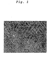
- Fig. 1 is an FE-SEM photograph showing a nitride layer structure of the Fe-C-Mn coarse grain steel containing 0.002 mass % C. It can be seen from this FE-SEM photograph that streaky nitrides are formed in ferrite grains.
- Fig. 2 is a bar graph showing Vickers hardness of a raw material and a surface of a nitride layer of the Fe-C-Mn coarse grain steel containing 0.002 mass % C and the Fe-C-Mn ultra fine grain steel containing 0.05 mass % C. Vickers hardness was measured by applying a load of 1 kg onto a surface of a plate which was nitrified by plasma and has a thickness of 1 mm. It can be seen that even the Fe-C-Mn steel having a simple composition is hardened by nitrifying and that the ultra fine grain steel is more heavily hardened by nitrifying.
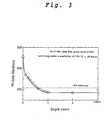
- Fig. 3 is a graph showing hardness distribution after nitrifying of a fatigue test piece of the Fe-C-Mn ultra fine grain steel containing 0.05 mass % C.
- the nitrifying was performed by plasma under a condition of 550 °C ⁇ 26 hours and a fatigue test piece was formed into a shape of a sand clock having a diameter ⁇ of 6 mm at a test portion. Vickers hardness was measured in a state where a load of 0.2 kg is applied to the test piece. From the hardness distribution shown in Fig. 3, a nitride layer is estimated to be about 1mm in depth. Moreover, it is recognized that hardness of a matrix after nitrifying is lower than a raw material before nitrifying.
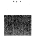
- Fig. 4 is a FE-SEM photograph showing a matrix structure after nitrifying, the ferrite grains were coarsened to a size of from 5 ⁇ m to 10 ⁇ m.
- Fig. 5 is a graph showing hardness distribution after nitrifying of a Fe-C-Mn-Si coarse grain steel containing 0.25 mass % C and 0.37 mass % Mn (circular bar having a diameter of 16 mm) which was subjected to nitrifying under a conditions of 500 °C ⁇ 16 hours.
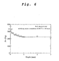
- Fig. 6 is a graph showing hardness distribution after nitrifying of a Fe-C-Mn-Si coarse grain steel containing 0.45 mass % C and 0.83 mass % Mn (circular bar having a diameter of 16 mm) which was subjected to nitrifying under a condition of 500 °C ⁇ 16 hours.
- the necessary amount of Mn is more than 0.37 mass % so as to form a deep effective nitride layer, that is, hardened layer.
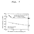
- Fig. 7 is a graph showing results of fatigue tests of a raw material and a nitrified material of the Fe-C-Mn ultra fine grain steel containing 0.05 mass % C in comparison with each other.
- a Clauze type rotary bending fatigue test apparatus and a test piece shaped like a sand clock and having a test portion of 6 mm of diameter ⁇ were used.
- the nitrified material its surface was removed about 0.1 mm by grinding to remove defects introduced at the time of nitrifying.
- the nitrified material had fatigue strength enhanced greatly as compared with the raw material though its matrix was coarsened, and a fatigue limit of the raw material was 375 MPa whereas a fatigue limit of the nitrified material was 640 MPa.
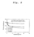
- a fatigue test piece made of a Fe-C-Mn-Si based ultra fine grain steel and having a test portion of 6 mm in diameter was held at 500 °C for 30 hours by use of an ordinary electric furnace so as to simulate a nitrifying process performed at high temperature for a long time and then a change in hardness of the test piece was measured.
- a graph of Fig. 8 in the ultra fine grain steel containing 0.05 mass % C and the ultra fine grain steel containing 0.15 mass % C, when they were held at high temperature for about 3 hours, hardness decreased to about Hv 200 and grain coarsening was recognized.
- Figs. 9(a) and 9(b) are FE-SEM photographs showing a base material structures before nitrifying of the Fe-C-Mn-Si ultra fine grain steel containing 0.15 mass % C and the Fe-C-Mn-Si ultra fine grain steel containing 0.45 mass % C, respectively.
- Many Fe 3 Cs (white speckles) precipitated in the Fe-C-Mn-Si ultra fine grain steel containing 0.45 mass % C. It is estimated that grains of the Fe-C-Mn-Si ultra fine grain steel containing 0.45 mass % C were not coarsened by grain growth suppressing effect of the Fe 3 C precipitates.
- ferrite grain size was 1 ⁇ m or less in both of the ultra fine grain steels.
- Fig. 10 is a graph showing a grain growth suppressing effect in the ultra fine grain steel containing 0.15 mass % C and 0.1 mass % P.
- Fig. 10 in the ultra fine grain steel containing 0.15 mass % C and 0.1 mass % P, hardness decreased slightly as compared with the ultra fine grain steel containing 0.15 mass % C and hence grain coarsening was suppressed.
- the cause is estimated to be grain growth suppressing effect by solid solution of P.
- the grain growth suppressing effect of a carbide or solid solute element prevents or suppresses grain coarsening to maintain an ultra fine grain structure and that nitrifying of a long time is possible while preserving high strength.
- a Fe-C-Mn-Si ultra fine grain steel containing 0.45 mass % C that utilizes Fe 3 C precipitates, a Fe-C-Mn-Si ultra fine grain steel containing 0.15 mass % C and 0.1 mass % P that utilizes solid solution of P, and a Fe-C-Mn-Si based ultra-refined steel containing 0.45 mass % C and 0.1 mass % P that utilizes both of the Fe 3 C precipitate and the solid solution of P were actually nitrified and the fatigue test was conducted.
- the nitrifying was performed by plasma under a condition of 500 °C ⁇ 16 hours.
- Fig. 11 is a graph showing hardness distribution of the Fe-C-Mn-Si ultra fine grain steel containing 0.45 mass % C and 0.1 mass % P which was subjected to the nitrifying. As can be seen from the graph shown in Fig.
- the fatigue limits after nitrifying were 700 MPa for the ultra fine grain steel containing 0.45 mass % C, 780 MPa for the ultra fine grain steel containing 0.15 mass % C and 0.1 mass % P, and 700 MPa for the ultra fine grain steel containing 0.45 mass % C and 0.1 mass % P.
- the Vickers hardness of the matrixes of the respective steels are 300, 308, and 339, so that the ratios of fatigue limit/Vickers hardness of a matrix are 2.33, 2.53, and 2.06 and all of them are larger than 1.6.
- the ultra fine grain steel containing 0.45 mass % C and 0.1 mass % P can provide a fatigue limit beyond 780 MPa of the ultra fine grain steel containing 0.15 mass % C and 0.1 mass % P because the ultra fine grain steel containing 0.45 mass % C and 0.1 mass % P has higher hardness.
- the present invention is not limited to the above-described embodiments and examples. Needless to say, the invention can be modified in the details such as chemical components of steel, nitrifying conditions, and nitrifying method.
- the present invention can provide an ultra fine grain steel having a nitride layer that is formed without adding alloy elements such as Cr and Mo, which are expensive and detrimental at the time of recycling, and the steel whose fatigue strength is enhanced.
Landscapes
- Chemical & Material Sciences (AREA)
- Engineering & Computer Science (AREA)
- Materials Engineering (AREA)
- Mechanical Engineering (AREA)
- Metallurgy (AREA)
- Organic Chemistry (AREA)
- Chemical Kinetics & Catalysis (AREA)
- Solid-Phase Diffusion Into Metallic Material Surfaces (AREA)
- Heat Treatment Of Steel (AREA)
Abstract
Description
Patent document 1: Japanese Patent Publication No. 2000-309850
Non-patent document 1: Doctoral Dissertation, Hideyuki Kuwahara, November in 1992, Kyoto University
| (a) Coarse grain steel | |||||||
| Material | C | Si | Mn | P | S | Ferrite grain size (µm) | |
| Fe-C-Mn | 0.002C | 0.002 | 0.01 | 1.98 | 0.001 | 0.002 | 20.0 |
| Fe-C-Mn-Si | 0.25C | 0.27 | 0.23 | 0.37 | 0.008 | 0.030 | 20.0 |
| 0.45C | 0.43 | 0.22 | 0.83 | 0.017 | 0.016 | - | |
| (b) Ultra fine grain steel | |||||||
| Material | C | Si | Mn | P | S | Ferrite grain size (µm) | |
| Fe-C-Mn | 0.050 | 0.05 | 0.01 | 1.98 | 0.021 | 0.001 | 1.7 |
| Fe-C-Mn-Si | 0.15C | 0.14 | 0.31 | 1.51 | 0.001 | 0.001 | 0.5 |
| 0.45C | 0.43 | 0.31 | 1.50 | 0.001 | 0.001 | 0.7 | |
| 0.76C | 0.76 | 0.31 | 1.43 | 0.012 | 0.004 | 0.5 | |
| 0.90C | 0.89 | 0.30 | 1.51 | 0.002 | 0.001 | 0.5 | |
| 0.15C-0.1P | 0.14 | 0.30 | 1.48 | 0.093 | 0.001 | 0.6 | |
| 0.45C-0.1P | 0.45 | 0.30 | 1.49 | 0.100 | 0.001 | 0.5 |
| (a) Coarse grain steel | ||||
| Material | Tensile strength (MPa) | Total elongation (%) | Vickers hardness | |
| Fe-C-Mn | 0.002C | - | - | 114 |
| Fe-C-Mn-Si | 0.25C | 511 | 34 | 155 |
| 0.45C | 706 | 25 | 230 | |
| (b) Ultra fine grain steel | ||||
| Material | Tensile strength (MPa) | Total elongation (%) | Vickers hardness | |
| Fe-C-Mn | 0.05C | 645 | 13 | 216 |
| Fe-C-Mn-Si | 0.15C | 842 | 17 | 286 |
| 0.45C | 952 | 17 | 300 | |
| 0.75C | 1143 | 12 | 360 | |
| 0.90C | - | - | 364 | |
| 0.15C-0.1P | 926 | 13 | 308 | |
| 0.45C-0.1P | 1048 | 15 | 339 |
| Fatigue limit (MPa) | |||||
| 0.45C | 0.15C-0.1P | 0.45C-0.1P | |||
| Fe-C-Mn-Si | Raw material | 500 | 520 | 580 | |
| | 700 | 780 | 700 |
Claims (9)
- An ultra fine grain steel having a nitride layer, wherein the steel has a ferrite grain structure having an average grain size of 3 µm or less and the nitride layer is formed on a surface of the steel.
- The ultra fine grain steel having a nitride layer as claimed in claim 1, wherein grain growth at a time of nitrifying is suppressed by precipitation of carbide or addition of a solid solute element or both of them.
- The ultra fine grain steel having a nitride layer as claimed in claim 1 or claim 2, wherein the amount of C is 0.01 mass % or more.
- The ultra fine grain steel having a nitride layer as claimed in any one of claims 1, 2, or 3, wherein at least one element selected from a group consisting of Mn, Cr, Mo, Ti, Nb, V and P is added.
- The ultra fine grain steel having a nitride layer as claimed in claim 4, wherein the amount of Mn is 0.4 mass % or more.
- The ultra fine grain steel having a nitride layer as claimed in claim 4 or 5, wherein the amount of P is 0.035 mass % or more.
- The ultra fine grain steel having a nitride layer as claimed in any one of claims 4, 5, or 6, wherein the steel is a carbon steel and the total amount of Cr, Mo, Ti, Nb, and V is 0.1 mass % or less.
- The ultra fine grain steel having a nitride layer as claimed in any one of claims 1, 2, 3, 4, 5, 6, or 7, wherein a fatigue limit is 1.6 times larger than Vickers hardness of a base material.
- A molded part, a part, or a member which is formed from the ultra fine grain steel having a nitride layer as claimed in any one of claims 1, 2, 3, 4, 5, 6, 7, or 8.
Applications Claiming Priority (3)
| Application Number | Priority Date | Filing Date | Title |
|---|---|---|---|
| JP2002303658A JP3931230B2 (en) | 2002-10-17 | 2002-10-17 | Ultrafine grained steel with nitrided layer |
| JP2002303658 | 2002-10-17 | ||
| PCT/JP2003/013308 WO2004035850A1 (en) | 2002-10-17 | 2003-10-17 | Superfine grain steel having nitrided layer |
Publications (2)
| Publication Number | Publication Date |
|---|---|
| EP1580291A1 true EP1580291A1 (en) | 2005-09-28 |
| EP1580291A4 EP1580291A4 (en) | 2006-01-18 |
Family
ID=32105079
Family Applications (1)
| Application Number | Title | Priority Date | Filing Date |
|---|---|---|---|
| EP03808902A Withdrawn EP1580291A4 (en) | 2002-10-17 | 2003-10-17 | SUPERFIN PARTICLE STEEL WITH NITRIDEE SURFACE |
Country Status (6)
| Country | Link |
|---|---|
| US (1) | US20050241733A1 (en) |
| EP (1) | EP1580291A4 (en) |
| JP (1) | JP3931230B2 (en) |
| KR (1) | KR20050067184A (en) |
| CN (1) | CN100359033C (en) |
| WO (1) | WO2004035850A1 (en) |
Cited By (1)
| Publication number | Priority date | Publication date | Assignee | Title |
|---|---|---|---|---|
| US8070888B2 (en) * | 2005-02-28 | 2011-12-06 | National Institute For Materials Science | High strength formed article comprising hyperfine grain structure steel and manufacturing method of the same |
Families Citing this family (1)
| Publication number | Priority date | Publication date | Assignee | Title |
|---|---|---|---|---|
| JP4009313B2 (en) * | 2006-03-17 | 2007-11-14 | 株式会社神戸製鋼所 | High strength steel material excellent in weldability and method for producing the same |
Family Cites Families (11)
| Publication number | Priority date | Publication date | Assignee | Title |
|---|---|---|---|---|
| JPS5917167B2 (en) * | 1980-06-09 | 1984-04-19 | 株式会社不二越 | How to harden steel |
| JPH07216497A (en) * | 1994-02-03 | 1995-08-15 | Sumitomo Metal Ind Ltd | High-fatigue-strength thin steel plate or thin steel plate part and manufacturing method thereof |
| JP2979987B2 (en) * | 1994-12-20 | 1999-11-22 | 住友金属工業株式会社 | Steel for soft nitriding |
| JPH10219393A (en) * | 1997-02-04 | 1998-08-18 | Sumitomo Metal Ind Ltd | Steel material for nitrocarburizing, nitrocarburizing component and method of manufacturing the same |
| CN1121502C (en) * | 1997-09-22 | 2003-09-17 | 科学技术厅金属材料技术研究所 | Super fine organization steel and method for mfg. same |
| JP2000080435A (en) * | 1998-08-31 | 2000-03-21 | Japan Science & Technology Corp | High-strength P-added steel and its manufacturing method |
| JP4243667B2 (en) * | 1999-02-26 | 2009-03-25 | 独立行政法人物質・材料研究機構 | High strength and toughness low carbon steel bar |
| US6386810B1 (en) * | 1999-05-21 | 2002-05-14 | Hiroshi Onoe | High strength screw |
| JP4164589B2 (en) * | 1999-08-31 | 2008-10-15 | 独立行政法人物質・材料研究機構 | Manufacturing method of ultra-fine structure steel |
| JP3845696B2 (en) * | 2000-02-25 | 2006-11-15 | 独立行政法人物質・材料研究機構 | Method for producing ultrafine-grained ferritic steel |
| JP4374196B2 (en) * | 2002-02-19 | 2009-12-02 | 新日本製鐵株式会社 | High-strength steel sheet having fine structure excellent in workability, plating property and toughness, and method for producing the same |
-
2002
- 2002-10-17 JP JP2002303658A patent/JP3931230B2/en not_active Expired - Lifetime
-
2003
- 2003-10-17 KR KR1020057006535A patent/KR20050067184A/en not_active Ceased
- 2003-10-17 CN CNB2003801015127A patent/CN100359033C/en not_active Expired - Fee Related
- 2003-10-17 WO PCT/JP2003/013308 patent/WO2004035850A1/en not_active Ceased
- 2003-10-17 US US10/531,319 patent/US20050241733A1/en not_active Abandoned
- 2003-10-17 EP EP03808902A patent/EP1580291A4/en not_active Withdrawn
Cited By (1)
| Publication number | Priority date | Publication date | Assignee | Title |
|---|---|---|---|---|
| US8070888B2 (en) * | 2005-02-28 | 2011-12-06 | National Institute For Materials Science | High strength formed article comprising hyperfine grain structure steel and manufacturing method of the same |
Also Published As
| Publication number | Publication date |
|---|---|
| WO2004035850A1 (en) | 2004-04-29 |
| JP2004137561A (en) | 2004-05-13 |
| CN1705762A (en) | 2005-12-07 |
| JP3931230B2 (en) | 2007-06-13 |
| KR20050067184A (en) | 2005-06-30 |
| CN100359033C (en) | 2008-01-02 |
| US20050241733A1 (en) | 2005-11-03 |
| EP1580291A4 (en) | 2006-01-18 |
Similar Documents
| Publication | Publication Date | Title |
|---|---|---|
| EP2578717B1 (en) | Steel for nitriding purposes, and nitrided member | |
| EP1403391B1 (en) | Martensitic stainless steel | |
| CN102812145A (en) | High-strength steel and high-strength bolt with excellent resistance to delayed fracture, and manufacturing method therefor | |
| JPH0867962A (en) | Rolling bearing | |
| WO2012077705A1 (en) | Gas-carburized steel component with excellent surface fatigue strength, gas-carburizing steel material, and process for producing gas-carburized steel component | |
| EP2955242B1 (en) | Steel sheet for nitriding and production method therefor | |
| JPH06293939A (en) | Bearing parts with excellent high temperature rolling fatigue | |
| CN103827334B (en) | Maraging steel | |
| JP2003113449A (en) | High strength and high toughness stainless steel sheet excellent in delayed fracture resistance and method for producing the same | |
| CN102791890B (en) | Spring steel and surface treatment method for steel material | |
| JP3792341B2 (en) | Soft nitriding steel with excellent cold forgeability and pitting resistance | |
| JP7295378B2 (en) | Gas nitrocarburized part and its manufacturing method | |
| CN107849679A (en) | Nitrogen treatment steel part and its manufacture method | |
| JP6438253B2 (en) | GAME STEEL BALL AND MANUFACTURING METHOD THEREOF | |
| JP5146063B2 (en) | High strength steel with excellent internal fatigue damage resistance and method for producing the same | |
| US20050241733A1 (en) | Superfine grain steel having nitrided layer | |
| JP3471576B2 (en) | Surface high hardness, high corrosion resistance, high toughness martensitic stainless steel | |
| CN108368576A (en) | Nitrogenize board member and its manufacturing method | |
| JPH0617225A (en) | Carburized bearing parts with excellent rolling fatigue | |
| JP2007332421A (en) | Method for manufacturing soft nitrided parts | |
| JPH05140696A (en) | Bearing steel and method of manufacturing bearing parts | |
| JP3340016B2 (en) | Structural steel for soft nitriding | |
| JPH06228734A (en) | Production of steel for clutch diaphragm spring | |
| JP6953871B2 (en) | Carburized parts and carburized nitride parts | |
| JP2000239800A (en) | High-strength metastable austenitic stainless steel sheet for blades having high elasticity and method for producing the same |
Legal Events
| Date | Code | Title | Description |
|---|---|---|---|
| PUAI | Public reference made under article 153(3) epc to a published international application that has entered the european phase |
Free format text: ORIGINAL CODE: 0009012 |
|
| 17P | Request for examination filed |
Effective date: 20050511 |
|
| AK | Designated contracting states |
Kind code of ref document: A1 Designated state(s): AT BE BG CH CY CZ DE DK EE ES FI FR GB GR HU IE IT LI LU MC NL PT RO SE SI SK TR |
|
| A4 | Supplementary search report drawn up and despatched |
Effective date: 20051202 |
|
| RIC1 | Information provided on ipc code assigned before grant |
Ipc: C22C 38/38 20000101ALI20051128BHEP Ipc: C22C 38/00 19740701AFI20040504BHEP Ipc: C23C 8/26 19850101ALI20051128BHEP |
|
| RBV | Designated contracting states (corrected) |
Designated state(s): DE FR GB IT SE |
|
| 17Q | First examination report despatched |
Effective date: 20060330 |
|
| RBV | Designated contracting states (corrected) |
Designated state(s): DE FR GB IT SE |
|
| STAA | Information on the status of an ep patent application or granted ep patent |
Free format text: STATUS: THE APPLICATION IS DEEMED TO BE WITHDRAWN |
|
| 18D | Application deemed to be withdrawn |
Effective date: 20080722 |