EP1580061A1 - Beam axle with integral sensor mount and target portion for the sensor - Google Patents
Beam axle with integral sensor mount and target portion for the sensor Download PDFInfo
- Publication number
- EP1580061A1 EP1580061A1 EP05075361A EP05075361A EP1580061A1 EP 1580061 A1 EP1580061 A1 EP 1580061A1 EP 05075361 A EP05075361 A EP 05075361A EP 05075361 A EP05075361 A EP 05075361A EP 1580061 A1 EP1580061 A1 EP 1580061A1
- Authority
- EP
- European Patent Office
- Prior art keywords
- sensor
- axle
- shaft
- tubular portion
- flat
- Prior art date
- Legal status (The legal status is an assumption and is not a legal conclusion. Google has not performed a legal analysis and makes no representation as to the accuracy of the status listed.)
- Granted
Links
Images


Classifications
-
- B—PERFORMING OPERATIONS; TRANSPORTING
- B60—VEHICLES IN GENERAL
- B60B—VEHICLE WHEELS; CASTORS; AXLES FOR WHEELS OR CASTORS; INCREASING WHEEL ADHESION
- B60B35/00—Axle units; Parts thereof ; Arrangements for lubrication of axles
- B60B35/12—Torque-transmitting axles
- B60B35/121—Power-transmission from drive shaft to hub
-
- B—PERFORMING OPERATIONS; TRANSPORTING
- B60—VEHICLES IN GENERAL
- B60K—ARRANGEMENT OR MOUNTING OF PROPULSION UNITS OR OF TRANSMISSIONS IN VEHICLES; ARRANGEMENT OR MOUNTING OF PLURAL DIVERSE PRIME-MOVERS IN VEHICLES; AUXILIARY DRIVES FOR VEHICLES; INSTRUMENTATION OR DASHBOARDS FOR VEHICLES; ARRANGEMENTS IN CONNECTION WITH COOLING, AIR INTAKE, GAS EXHAUST OR FUEL SUPPLY OF PROPULSION UNITS IN VEHICLES
- B60K17/00—Arrangement or mounting of transmissions in vehicles
- B60K17/22—Arrangement or mounting of transmissions in vehicles characterised by arrangement, location, or type of main drive shafting, e.g. cardan shaft
-
- B—PERFORMING OPERATIONS; TRANSPORTING
- B60—VEHICLES IN GENERAL
- B60B—VEHICLE WHEELS; CASTORS; AXLES FOR WHEELS OR CASTORS; INCREASING WHEEL ADHESION
- B60B35/00—Axle units; Parts thereof ; Arrangements for lubrication of axles
- B60B35/12—Torque-transmitting axles
- B60B35/16—Axle housings
-
- B—PERFORMING OPERATIONS; TRANSPORTING
- B60—VEHICLES IN GENERAL
- B60G—VEHICLE SUSPENSION ARRANGEMENTS
- B60G17/00—Resilient suspensions having means for adjusting the spring or vibration-damper characteristics, for regulating the distance between a supporting surface and a sprung part of vehicle or for locking suspension during use to meet varying vehicular or surface conditions, e.g. due to speed or load
- B60G17/015—Resilient suspensions having means for adjusting the spring or vibration-damper characteristics, for regulating the distance between a supporting surface and a sprung part of vehicle or for locking suspension during use to meet varying vehicular or surface conditions, e.g. due to speed or load the regulating means comprising electric or electronic elements
- B60G17/019—Resilient suspensions having means for adjusting the spring or vibration-damper characteristics, for regulating the distance between a supporting surface and a sprung part of vehicle or for locking suspension during use to meet varying vehicular or surface conditions, e.g. due to speed or load the regulating means comprising electric or electronic elements characterised by the type of sensor or the arrangement thereof
-
- G—PHYSICS
- G01—MEASURING; TESTING
- G01P—MEASURING LINEAR OR ANGULAR SPEED, ACCELERATION, DECELERATION, OR SHOCK; INDICATING PRESENCE, ABSENCE, OR DIRECTION, OF MOVEMENT
- G01P1/00—Details of instruments
- G01P1/02—Housings
- G01P1/026—Housings for speed measuring devices, e.g. pulse generator
-
- B—PERFORMING OPERATIONS; TRANSPORTING
- B60—VEHICLES IN GENERAL
- B60B—VEHICLE WHEELS; CASTORS; AXLES FOR WHEELS OR CASTORS; INCREASING WHEEL ADHESION
- B60B2310/00—Manufacturing methods
- B60B2310/20—Shaping
- B60B2310/208—Shaping by forging
- B60B2310/2082—Shaping by forging by swaging
-
- B—PERFORMING OPERATIONS; TRANSPORTING
- B60—VEHICLES IN GENERAL
- B60B—VEHICLE WHEELS; CASTORS; AXLES FOR WHEELS OR CASTORS; INCREASING WHEEL ADHESION
- B60B2310/00—Manufacturing methods
- B60B2310/20—Shaping
- B60B2310/224—Shaping by rolling
-
- B—PERFORMING OPERATIONS; TRANSPORTING
- B60—VEHICLES IN GENERAL
- B60G—VEHICLE SUSPENSION ARRANGEMENTS
- B60G2204/00—Indexing codes related to suspensions per se or to auxiliary parts
- B60G2204/10—Mounting of suspension elements
- B60G2204/11—Mounting of sensors thereon
- B60G2204/115—Wheel hub bearing sensors
-
- B—PERFORMING OPERATIONS; TRANSPORTING
- B60—VEHICLES IN GENERAL
- B60G—VEHICLE SUSPENSION ARRANGEMENTS
- B60G2206/00—Indexing codes related to the manufacturing of suspensions: constructional features, the materials used, procedures or tools
- B60G2206/01—Constructional features of suspension elements, e.g. arms, dampers, springs
- B60G2206/50—Constructional features of wheel supports or knuckles, e.g. steering knuckles, spindle attachments
-
- B—PERFORMING OPERATIONS; TRANSPORTING
- B60—VEHICLES IN GENERAL
- B60G—VEHICLE SUSPENSION ARRANGEMENTS
- B60G2400/00—Indexing codes relating to detected, measured or calculated conditions or factors
- B60G2400/20—Speed
- B60G2400/208—Speed of wheel rotation
-
- B—PERFORMING OPERATIONS; TRANSPORTING
- B60—VEHICLES IN GENERAL
- B60G—VEHICLE SUSPENSION ARRANGEMENTS
- B60G2401/00—Indexing codes relating to the type of sensors based on the principle of their operation
- B60G2401/17—Magnetic/Electromagnetic
- B60G2401/172—Hall effect
-
- B—PERFORMING OPERATIONS; TRANSPORTING
- B60—VEHICLES IN GENERAL
- B60K—ARRANGEMENT OR MOUNTING OF PROPULSION UNITS OR OF TRANSMISSIONS IN VEHICLES; ARRANGEMENT OR MOUNTING OF PLURAL DIVERSE PRIME-MOVERS IN VEHICLES; AUXILIARY DRIVES FOR VEHICLES; INSTRUMENTATION OR DASHBOARDS FOR VEHICLES; ARRANGEMENTS IN CONNECTION WITH COOLING, AIR INTAKE, GAS EXHAUST OR FUEL SUPPLY OF PROPULSION UNITS IN VEHICLES
- B60K17/00—Arrangement or mounting of transmissions in vehicles
- B60K17/04—Arrangement or mounting of transmissions in vehicles characterised by arrangement, location or kind of gearing
- B60K17/16—Arrangement or mounting of transmissions in vehicles characterised by arrangement, location or kind of gearing of differential gearing
-
- B—PERFORMING OPERATIONS; TRANSPORTING
- B60—VEHICLES IN GENERAL
- B60W—CONJOINT CONTROL OF VEHICLE SUB-UNITS OF DIFFERENT TYPE OR DIFFERENT FUNCTION; CONTROL SYSTEMS SPECIALLY ADAPTED FOR HYBRID VEHICLES; ROAD VEHICLE DRIVE CONTROL SYSTEMS FOR PURPOSES NOT RELATED TO THE CONTROL OF A PARTICULAR SUB-UNIT
- B60W2520/00—Input parameters relating to overall vehicle dynamics
- B60W2520/28—Wheel speed
Definitions
- the present invention generally relates to vehicle axles and more particularly to an axle assembly that may include an axle housing with an integral mount for a wheel speed sensor and an axle shaft with an integral sensor target or exciter ring.
- Modern vehicles typically include an axle assembly having a housing and a differential assembly.
- the housing includes a cavity into which the differential assembly is positioned.
- the differential assembly is rotatably supported by the housing within the cavity.
- the differential assembly is mechanically coupled to the vehicle engine by a drive shaft.
- the differential assembly is also coupled to the vehicle drive wheels via a pair of axle shafts.
- the differential assembly regulates drive torque between the axle shafts, thereby permitting the shafts to rotate at different velocities as when one of the drive wheels is slipping.
- Modern automotive vehicles frequently include systems, such as traction and stability control systems, that identify wheel slip conditions and responsively control the vehicle (e.g., engine, transmission, braking system) to reduce or eliminate wheel slip in certain instances.
- a sensor is typically employed to sense the speed of a wheel or another component, such as the axle shaft, that has the rotational speed of the wheel.
- One relatively common arrangement utilizes a Hall-effect sensor, which is mounted to the axle housing, and an exciter ring that is typically press-fit to the axle shaft.
- This arrangement typically employs a relatively large boss that is welded to the housing of the axle. Once the boss has been secured to the axle housing, several machining steps are required to drill and ream holes for the sensor, as well as to drill and tap a hole for the fastener that is employed to both orient the sensor and secure the sensor to the axle housing.
- an arrangement that did not employ a discrete boss would be advantageous in that it would eliminate a part, eliminate the welding operation and would permit the sensor to be mounted relatively further outboard toward the brake mount flange where it would permit the sensor to mounted relatively closer to an outboard axle shaft support bearing. This latter aspect is important in that the sensor could be located to an area where the axle shaft experienced relatively less deflection. Also, an arrangement that did not employ a discrete sensor target, such as a sensor ring, would be advantageous in that it would eliminate a part.
- the present teachings provide a vehicle axle assembly having an axle housing, an axle shaft and a sensor.
- the axle housing has a tubular portion.
- a flat is formed on an annular wall of the tubular portion proximate a distal end of the tubular portion, and a hole, which intersects the flat, is formed through the tubular portion.
- the axle shaft has an integrally formed target portion that includes a plurality of teeth.
- the sensor is mounted in the hole and abuts the flat to space a tip of the sensor apart from the teeth of the target portion by a predetermined distance.
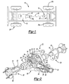
- FIG. 1 is a schematic illustration of an exemplary vehicle constructed in accordance with the teachings of the present invention
- Figure 2 is a partially cut away perspective view of a portion of the vehicle of Figure 1 illustrating the rear axle assembly and propshaft in greater detail;
- Figure 3 is a sectional view of a portion of the rear axle assembly
- Figure 4 is an exploded perspective view in partial section of the rear axle assembly.
- Figure 5 is a sectional view illustrating a portion of a second rear axle assembly constructed in accordance with the teachings of the present invention.
- a vehicle having an axle assembly that is constructed in accordance with the teachings of the present invention is generally indicated by reference numeral 10.
- the vehicle 10 includes a driveline 12 drivable via a connection to a power train 14.
- the power train 14 includes an engine 16 and a transmission 18.
- the driveline 12 includes a propshaft assembly 20, a rear axle assembly 22 and a plurality of wheels 24.
- the engine 16 is mounted in an in-line or longitudinal orientation along the axis of the vehicle 10 and its output is selectively coupled via a conventional clutch to the input of the transmission 18 to transmit rotary power (i.e., drive torque) therebetween.
- the input of the transmission 18 is commonly aligned with the output of the engine 16 for rotation about a rotary axis.
- the transmission 18 also includes an output 18a and a gear reduction unit (not shown).
- the gear reduction unit is operable for coupling the transmission input to the output 18a of the transmission at a predetermined gear speed ratio.
- the propshaft assembly 20 is coupled for rotation with the output 18a of the transmission 18.
- Drive torque is transmitted through the propshaft assembly 20 to the rear axle assembly 22 where it is selectively apportioned in a predetermined manner to the left and right rear wheels 24a and 24b, respectively.
- the rear axle assembly 22 is shown to include a differential assembly 26, a left axle shaft assembly 28 and a right axle shaft assembly 30.
- the differential assembly 26 includes a housing 32, a differential unit 34 and an input shaft assembly 36.
- the housing 32 supports the differential unit 34 for rotation about a first axis 38 and further supports the input shaft assembly 36 for rotation about a second axis 40 that is perpendicular to the first axis 38.
- the housing 32 includes a wall member 42 that defines a central cavity 44 having a left axle aperture 46, a right axle aperture 48 and an input shaft aperture 68.
- the housing 32 may include a pair of axle tubes 52 that are fixedly mounted to the wall member 42.
- the axle tube 52 may include an annular collar 54, which may be formed by swaging or rolling, so as to provide a portion of the axle tube 52 with a wall thickness that is relatively thicker than adjacent portions of the axle tube 52.
- a flat 56 may be formed (e.g., cast, machined) into the annular collar 54 of the axle tube 52. The flat 56 may be offset from the first axis 38 by a predetermined distance and may form a datum that will be discussed in greater detail, below.
- a hole 58, which intersects the flat 56, may be formed through the annular collar 54.
- the differential unit 34 is disposed within the central cavity 44 of the housing 32 and includes a gearset 60.
- the gearset 60 includes first and second side gears 62 and 64, respectively, and a plurality of pinions (not shown).
- the left and right axle shaft assemblies 28 and 30 extend through the left and right axle apertures 46 and 48, respectively, where they are coupled for rotation about the first axis 38 with the first and second side gears 62 and 64, respectively.
- a flange 66 which may be employed to support a brake assembly (not shown), may be coupled to a distal end of both the left and right axle shaft assemblies 28 and 30.
- the input shaft assembly 36 extends through the input shaft aperture 68 where it is supported in the housing 32 for rotation about the second axis 40.
- the input shaft assembly 36 is coupled for rotation with the propshaft assembly 20 and is operable for transmitting drive torque to the differential unit 34. More specifically, the drive torque received by the input shaft assembly 36 is transmitted to the differential unit 34 such that drive torque is distributed to the first and second side gears 62 and 64, causing the left and right axle shaft assemblies 28 and 30 to rotate about the first axis 38.
- the left and right axle shaft assemblies 28 and 30 may include an axle shaft 70 that is supported for rotation in the axle tube 52 about the first axis 38.
- Each of the axle shafts 70 may include an externally splined portion 72 that may meshingly engage a mating internally splined portion (not specifically shown) that is formed into the first and second side gears 62 and 64, respectively.
- the left axle shaft assembly 28 is shown in greater detail. As one of ordinary skill in the art would appreciate from this disclosure, the left side of the axle assembly is a mirror image of the right side. As such, a detailed discussion of the left side will suffice for both.
- the left axle shaft assembly 28 may further include a bearing 74, an axle shaft 70 and a sensor 76 that is coupled to the axle tube 52.
- a bearing 74 may further include a bearing 74, an axle shaft 70 and a sensor 76 that is coupled to the axle tube 52.
- the axle shaft 70 may be integrally formed and may include a bearing support portion 78, a target portion 80, and an intermediate portion 82 onto which the externally splined portion 72 (Fig. 2) may be formed.
- the target portion 80 may have a plurality of target features, such as radially-extending, circumferentially spaced-apart teeth 84 that may be formed in a roll forming operation.
- the bearing support portion 78 is formed with a first diameter
- the intermediate portion 82 is formed with a second, relatively smaller diameter
- the target portion 80 is formed with a third diameter that is intermediate the diameters of the bearing support portion 78 and the intermediate portion 82.
- Appropriately sized and contoured transition sections 86 may be employed between the bearing support portion 78, the target portion 80 and the intermediate portion 82 so as to reduce stress concentrations, etc.
- the bearing 74 may support the axle shaft 70 for rotation in the axle tube 52.
- the bearing 74 may be pressed into the axle tube 52 such that elements (e.g., rollers 88) support the bearing support portion 78 of the axle shaft 70 when the axle shaft 70 is installed thereto.
- a conventional seal 90 may be coupled to the axle tube 52 in a conventional manner to retain lubricating fluids in the axle tube 52 as well as to inhibit the transmission of dirt, debris and other contaminants to the interior of the axle tube 52.
- the seal 90 may include one or more seal lips 92 that sealingly engage the bearing support portion 78 of the axle shaft 70.
- the progressively increasing sizes of the intermediate portion 82, the target portion 80 and the bearing support portion 78 permit the axle shaft 70 to be installed to the axle tube 52 with relatively less risk of damaging the seal 90 as compared with the known axle assembly arrangements.
- the target portion 80 of the axle shaft 70 is relatively smaller in diameter than the bearing support portion 78 and moreover, the amount by which the axle shaft 70 may be tilted relative to the first axis 38 is limited as a result of the length of the intermediate portion 82.
- a sensor 76 which may be a Hall-effect sensor, may be installed directly to the axle tube 52.
- the sensor 76 includes a body portion 94 and an abutting flange 96 and the sensor 76 is an active Hall-effect sensor.
- the hole 58 in the axle tube 52 may including a mating threaded portion 98 that is configured to threadably receive the threads 100 that are formed on the body portion 94 of the sensor 76.
- the increased thickness of the annular collar 54 ensures that the threads 100 of the body portion 94 and the mating threaded portion 98 engage one another over a distance that is sufficient to fixedly but removably secure the sensor 76 to the axle tube 52.
- a sealant (not shown) may be applied to the threads 100 and/or a seal member, such as an O-ring (not shown), may be employed to form a seal against the axle tube 52 to inhibit fluid communication through the hole 58.
- the present configuration eliminates two components, i.e., a boss (not shown) that would otherwise be welded to the axle tube and a discrete sensor target (not shown) that would otherwise be coupled, e.g., press-fit, to the axle shaft.
- the reduction in part count not only reduces the overall cost of the system, it also improves the performance and reliability of the system through the elimination of stack-up.
- the location of the sensor 76 may be place relatively closer to the flange 66 that supports the brake assembly (not shown).
- the hole 58 has been described thus far as including a mating threaded portion 98 that is adapted to threadably engage the sensor 76, those skilled in the art will appreciate that the invention, in its broader aspects, may be constructed somewhat differently.
- another mechanical fastening means may be employed to secure the sensor to the axle tube 52 and/or to orient the sensor in a particular orientation as shown in Figure 5.
- the sensor 76a includes a mounting flange 120 that is axially spaced apart from and disposed about the tip 122 of the sensor 76a.
- the hole 58a in the axle tube 52a is not threaded but rather sized to receive a portion of the sensor 76a.
- a seal member such as an O-ring 124, may be fitted about the body of the sensor 76a and configured to sealingly engage the side of the hole 58a.
- An auxiliary hole 126 is also formed into or through the axle tube 52a and is sized to threadably engage a fastener 128 that is employed to both secure the sensor 76a to the axle tube 52a and orient the sensor 76a in a desired manner.
- the fastener 128 is fitted through an associated aperture 130 in the mounting flange 120 and threadably engages the auxiliary hole 126.
Landscapes
- Engineering & Computer Science (AREA)
- Mechanical Engineering (AREA)
- Physics & Mathematics (AREA)
- General Physics & Mathematics (AREA)
- Chemical & Material Sciences (AREA)
- Combustion & Propulsion (AREA)
- Transportation (AREA)
- Retarders (AREA)
- Transmission And Conversion Of Sensor Element Output (AREA)
Abstract
Description
- The present invention generally relates to vehicle axles and more particularly to an axle assembly that may include an axle housing with an integral mount for a wheel speed sensor and an axle shaft with an integral sensor target or exciter ring.
- Modern vehicles typically include an axle assembly having a housing and a differential assembly. The housing includes a cavity into which the differential assembly is positioned. The differential assembly is rotatably supported by the housing within the cavity. The differential assembly is mechanically coupled to the vehicle engine by a drive shaft. The differential assembly is also coupled to the vehicle drive wheels via a pair of axle shafts. The differential assembly regulates drive torque between the axle shafts, thereby permitting the shafts to rotate at different velocities as when one of the drive wheels is slipping.
- Modern automotive vehicles frequently include systems, such as traction and stability control systems, that identify wheel slip conditions and responsively control the vehicle (e.g., engine, transmission, braking system) to reduce or eliminate wheel slip in certain instances. In such systems, a sensor is typically employed to sense the speed of a wheel or another component, such as the axle shaft, that has the rotational speed of the wheel.
- One relatively common arrangement utilizes a Hall-effect sensor, which is mounted to the axle housing, and an exciter ring that is typically press-fit to the axle shaft. This arrangement typically employs a relatively large boss that is welded to the housing of the axle. Once the boss has been secured to the axle housing, several machining steps are required to drill and ream holes for the sensor, as well as to drill and tap a hole for the fastener that is employed to both orient the sensor and secure the sensor to the axle housing.
- While such arrangements are suited for their intended purpose, they are nonetheless susceptible to improvement. For example, an arrangement that did not employ a discrete boss would be advantageous in that it would eliminate a part, eliminate the welding operation and would permit the sensor to be mounted relatively further outboard toward the brake mount flange where it would permit the sensor to mounted relatively closer to an outboard axle shaft support bearing. This latter aspect is important in that the sensor could be located to an area where the axle shaft experienced relatively less deflection. Also, an arrangement that did not employ a discrete sensor target, such as a sensor ring, would be advantageous in that it would eliminate a part.
- Accordingly, a need exists for an axle assembly with a sensor mount which is smaller in size and reduces assembly time.
- In one form, the present teachings provide a vehicle axle assembly having an axle housing, an axle shaft and a sensor. The axle housing has a tubular portion. A flat is formed on an annular wall of the tubular portion proximate a distal end of the tubular portion, and a hole, which intersects the flat, is formed through the tubular portion. The axle shaft has an integrally formed target portion that includes a plurality of teeth. The sensor is mounted in the hole and abuts the flat to space a tip of the sensor apart from the teeth of the target portion by a predetermined distance.
- Further areas of applicability of the present invention will become apparent from the detailed description provided hereinafter. It should be understood that the detailed description and specific examples, while indicating the preferred embodiment of the invention, are intended for purposes of illustration only and are not intended to limit the scope of the invention.
- The present invention will become more fully understood from the detailed description and the accompanying drawings, wherein:
- Figure 1 is a schematic illustration of an exemplary vehicle constructed in accordance with the teachings of the present invention;
- Figure 2 is a partially cut away perspective view of a portion of the vehicle of Figure 1 illustrating the rear axle assembly and propshaft in greater detail;
- Figure 3 is a sectional view of a portion of the rear axle assembly;
- Figure 4 is an exploded perspective view in partial section of the rear axle assembly; and
- Figure 5 is a sectional view illustrating a portion of a second rear axle assembly constructed in accordance with the teachings of the present invention.
- The following description of the preferred embodiment is merely exemplary in nature and is in no way intended to limit the invention, its application, or uses.
- With reference to Figure 1 of the drawings, a vehicle having an axle assembly that is constructed in accordance with the teachings of the present invention is generally indicated by
reference numeral 10. Thevehicle 10 includes adriveline 12 drivable via a connection to apower train 14. Thepower train 14 includes anengine 16 and atransmission 18. Thedriveline 12 includes apropshaft assembly 20, arear axle assembly 22 and a plurality ofwheels 24. Theengine 16 is mounted in an in-line or longitudinal orientation along the axis of thevehicle 10 and its output is selectively coupled via a conventional clutch to the input of thetransmission 18 to transmit rotary power (i.e., drive torque) therebetween. The input of thetransmission 18 is commonly aligned with the output of theengine 16 for rotation about a rotary axis. Thetransmission 18 also includes anoutput 18a and a gear reduction unit (not shown). The gear reduction unit is operable for coupling the transmission input to theoutput 18a of the transmission at a predetermined gear speed ratio. Thepropshaft assembly 20 is coupled for rotation with theoutput 18a of thetransmission 18. Drive torque is transmitted through thepropshaft assembly 20 to therear axle assembly 22 where it is selectively apportioned in a predetermined manner to the left and rightrear wheels - With additional reference to Figure 2, the
rear axle assembly 22 is shown to include adifferential assembly 26, a leftaxle shaft assembly 28 and a rightaxle shaft assembly 30. Thedifferential assembly 26 includes ahousing 32, adifferential unit 34 and aninput shaft assembly 36. Thehousing 32 supports thedifferential unit 34 for rotation about afirst axis 38 and further supports theinput shaft assembly 36 for rotation about asecond axis 40 that is perpendicular to thefirst axis 38. - The
housing 32 includes awall member 42 that defines acentral cavity 44 having aleft axle aperture 46, aright axle aperture 48 and aninput shaft aperture 68. Thehousing 32 may include a pair ofaxle tubes 52 that are fixedly mounted to thewall member 42. With additional reference to Figure 3, theaxle tube 52 may include anannular collar 54, which may be formed by swaging or rolling, so as to provide a portion of theaxle tube 52 with a wall thickness that is relatively thicker than adjacent portions of theaxle tube 52. A flat 56 may be formed (e.g., cast, machined) into theannular collar 54 of theaxle tube 52. The flat 56 may be offset from thefirst axis 38 by a predetermined distance and may form a datum that will be discussed in greater detail, below. Ahole 58, which intersects theflat 56, may be formed through theannular collar 54. - The
differential unit 34 is disposed within thecentral cavity 44 of thehousing 32 and includes agearset 60. Thegearset 60 includes first andsecond side gears right axle apertures first axis 38 with the first andsecond side gears flange 66, which may be employed to support a brake assembly (not shown), may be coupled to a distal end of both the left and right axle shaft assemblies 28 and 30. - The
input shaft assembly 36 extends through theinput shaft aperture 68 where it is supported in thehousing 32 for rotation about thesecond axis 40. Theinput shaft assembly 36 is coupled for rotation with thepropshaft assembly 20 and is operable for transmitting drive torque to thedifferential unit 34. More specifically, the drive torque received by theinput shaft assembly 36 is transmitted to thedifferential unit 34 such that drive torque is distributed to the first andsecond side gears first axis 38. - The left and right axle shaft assemblies 28 and 30 may include an
axle shaft 70 that is supported for rotation in theaxle tube 52 about thefirst axis 38. Each of theaxle shafts 70 may include an externallysplined portion 72 that may meshingly engage a mating internally splined portion (not specifically shown) that is formed into the first andsecond side gears - With reference to Figure 3, the left
axle shaft assembly 28 is shown in greater detail. As one of ordinary skill in the art would appreciate from this disclosure, the left side of the axle assembly is a mirror image of the right side. As such, a detailed discussion of the left side will suffice for both. The leftaxle shaft assembly 28 may further include abearing 74, anaxle shaft 70 and asensor 76 that is coupled to theaxle tube 52. Those of ordinary skill in the art will appreciate from this disclosure that although the particular axle assembly illustrated has a semi-floating configuration, the teachings of the present invention are applicable to other types of axle assemblies, including full-floating axle assemblies. - The
axle shaft 70 may be integrally formed and may include abearing support portion 78, atarget portion 80, and an intermediate portion 82 onto which the externally splined portion 72 (Fig. 2) may be formed. Thetarget portion 80 may have a plurality of target features, such as radially-extending, circumferentially spaced-apartteeth 84 that may be formed in a roll forming operation. In the particular example provided, thebearing support portion 78 is formed with a first diameter, the intermediate portion 82 is formed with a second, relatively smaller diameter and thetarget portion 80 is formed with a third diameter that is intermediate the diameters of thebearing support portion 78 and the intermediate portion 82. Appropriately sized and contouredtransition sections 86 may be employed between the bearingsupport portion 78, thetarget portion 80 and the intermediate portion 82 so as to reduce stress concentrations, etc. - The
bearing 74 may support theaxle shaft 70 for rotation in theaxle tube 52. In this regard, the bearing 74 may be pressed into theaxle tube 52 such that elements (e.g., rollers 88) support thebearing support portion 78 of theaxle shaft 70 when theaxle shaft 70 is installed thereto. Aconventional seal 90 may be coupled to theaxle tube 52 in a conventional manner to retain lubricating fluids in theaxle tube 52 as well as to inhibit the transmission of dirt, debris and other contaminants to the interior of theaxle tube 52. Theseal 90 may include one ormore seal lips 92 that sealingly engage thebearing support portion 78 of theaxle shaft 70. - If employed, the progressively increasing sizes of the intermediate portion 82, the
target portion 80 and thebearing support portion 78 permit theaxle shaft 70 to be installed to theaxle tube 52 with relatively less risk of damaging theseal 90 as compared with the known axle assembly arrangements. In this regard, thetarget portion 80 of theaxle shaft 70 is relatively smaller in diameter than the bearingsupport portion 78 and moreover, the amount by which theaxle shaft 70 may be tilted relative to thefirst axis 38 is limited as a result of the length of the intermediate portion 82. - When the
axle shaft 70 is installed to theaxle tube 52, thetarget portion 80 is radially aligned to the flat 56 that is formed on anannular collar 54 of theaxle tube 52. Asensor 76, which may be a Hall-effect sensor, may be installed directly to theaxle tube 52. In the particular example provided, thesensor 76 includes abody portion 94 and an abuttingflange 96 and thesensor 76 is an active Hall-effect sensor. - The
hole 58 in theaxle tube 52 may including a mating threaded portion 98 that is configured to threadably receive thethreads 100 that are formed on thebody portion 94 of thesensor 76. The increased thickness of theannular collar 54 ensures that thethreads 100 of thebody portion 94 and the mating threaded portion 98 engage one another over a distance that is sufficient to fixedly but removably secure thesensor 76 to theaxle tube 52. Optionally, a sealant (not shown) may be applied to thethreads 100 and/or a seal member, such as an O-ring (not shown), may be employed to form a seal against theaxle tube 52 to inhibit fluid communication through thehole 58. - In contrast to the known arrangements, the present configuration eliminates two components, i.e., a boss (not shown) that would otherwise be welded to the axle tube and a discrete sensor target (not shown) that would otherwise be coupled, e.g., press-fit, to the axle shaft. The reduction in part count not only reduces the overall cost of the system, it also improves the performance and reliability of the system through the elimination of stack-up. Moreover, as a relatively large boss (not shown) is not employed, the location of the
sensor 76 may be place relatively closer to theflange 66 that supports the brake assembly (not shown). - While the
hole 58 has been described thus far as including a mating threaded portion 98 that is adapted to threadably engage thesensor 76, those skilled in the art will appreciate that the invention, in its broader aspects, may be constructed somewhat differently. For example, another mechanical fastening means may be employed to secure the sensor to theaxle tube 52 and/or to orient the sensor in a particular orientation as shown in Figure 5. In this embodiment, thesensor 76a includes a mountingflange 120 that is axially spaced apart from and disposed about thetip 122 of thesensor 76a. Thehole 58a in theaxle tube 52a is not threaded but rather sized to receive a portion of thesensor 76a. A seal member, such as an O-ring 124, may be fitted about the body of thesensor 76a and configured to sealingly engage the side of thehole 58a. Anauxiliary hole 126 is also formed into or through theaxle tube 52a and is sized to threadably engage afastener 128 that is employed to both secure thesensor 76a to theaxle tube 52a and orient thesensor 76a in a desired manner. Thefastener 128 is fitted through an associatedaperture 130 in the mountingflange 120 and threadably engages theauxiliary hole 126. - While the invention has been described in the specification and illustrated in the drawings with reference to various embodiments, it will be understood by those skilled in the art that various changes may be made and equivalents may be substituted for elements thereof without departing from the scope of the invention as defined in the claims. Furthermore, the mixing and matching of features, elements and/or functions between various embodiments is expressly contemplated herein so that one of ordinary skill in the art would appreciate from this disclosure that features, elements and/or functions of one embodiment may be incorporated into another embodiment as appropriate, unless described otherwise, above. Moreover, many modifications may be made to adapt a particular situation or material to the teachings of the invention without departing from the essential scope thereof. Therefore, it is intended that the invention not be limited to the particular embodiment illustrated by the drawings and described in the specification as the best mode presently contemplated for carrying out this invention, but that the invention will include any embodiments falling within the foregoing description and the appended claims.
Claims (17)
- An axle assembly for a vehicle, the axle assembly comprising:an axle housing having a tubular portion, a flat being formed on an annular wall of the tubular portion proximate a distal end of the tubular portion and a hole being formed through the tubular portion and intersecting the flat, the flat defining a datum surface;a bearing mounted in the tubular portion of the axle housing;an axle shaft disposed in the tubular portion of the axle housing and supported by the bearing, the axle shaft having a shaft end and an integrally formed target portion, the shaft end being adapted to be coupled to a differential side gear, the target portion including a plurality of teeth and being disposed proximate the bearing on a side that is between the shaft end and the bearing; anda sensor coupled directly to the tubular portion of the axle housing, the sensor being mounted in the hole and abutting the flat the thereby space a tip of the sensor apart from the teeth of the target portion by a predetermined distance.
- A method comprising:forming an axle housing with a tubular portion, the tubular portion including a flat that is formed on an exterior surface of the tubular portion and a sensor aperture being formed through the tubular portion generally transverse to the flat;mounting a bearing in the tubular portion proximate the hole;inserting an axle shaft into the tubular portion, the axle shaft including a target portion that is disposed in-line with the sensor aperture, the axle shaft having a shaft portion that is supported by the bearing; andinserting a sensor into the sensor aperture and abutting the sensor against the flat.
- The method of Claim 2, wherein the sensor is threadably engaged to the tubular portion.
- The method of Claim 2 or 3, wherein the sensor includes a mounting flange and a threaded fastener is employed to fixedly but removably couple the sensor to the tubular portion.
- The method of any of Claims 2-4, wherein the sensor is a Hall-effect sensor.
- The method of Claim 5, wherein the target portion includes a plurality of circumferentially spaced apart teeth.
- The method of Claim 6, wherein the teeth are integrally formed with the shaft structure.
- The method of any of Claims 2-7, wherein prior to inserting the axle shaft, the method further comprises installing a shaft seal to the tubular portion.
- The method of Claim 8, wherein the bearing is disposed between the shaft seal and the sensor aperture.
- An axle assembly for a vehicle, the axle assembly comprising:an axle housing defining a central cavity, the housing including a tubular portion with a sensor mount, the sensor mount including a flat, which is formed on an annular wall of the tubular portion proximate a distal end of the tubular portion, and a hole that is formed through the tubular portion and intersecting the flat, the flat defining a datum surface;a differential unit disposed in the central cavity, the differential unit including a side gear;an axle shaft disposed in the tubular portion of the axle housing, the axle shaft having a shaft end and a target portion, the shaft end being coupled to the side gear, the target portion including a plurality of teeth, the target portion being disposed proximate an end of the axle shaft opposite the shaft end; anda sensor coupled directly to the tubular portion of the axle housing, the sensor being mounted in the hole and abutting the flat to thereby space a tip of the sensor apart from the teeth of the target portion by a predetermined distance.
- The axle assembly of Claim 10, further comprising a bearing mounted in the tubular portion of the axle housing, the axle shaft being received into the bearing such that the bearing rotationally supports the axle shaft.
- The axle assembly of Claim 11, further comprising a shaft seal coupled to the tubular portion, the shaft seal sealingly engaging the axle shaft, the bearing being disposed between the shaft seal and the sensor.
- The axle assembly of Claim 12, wherein a portion of the axle shaft that is supported by the target portion has a diameter that is relatively larger than a diameter of the target portion.
- The axle assembly of any of Claims 10-13, wherein the axle shaft includes a shaft structure and the target portion is integrally formed with the shaft structure.
- The axle assembly of any of Claims 10-14, wherein the sensor is threadably engaged to the tubular portion.
- The axle assembly of any of Claims 10-15, wherein the sensor includes a mounting flange and a threaded fastener is employed to fixedly but removably couple the sensor to the tubular portion.
- The axle assembly of any of Claims 10-16, wherein the sensor is a Hall-effect sensor.
Applications Claiming Priority (2)
| Application Number | Priority Date | Filing Date | Title |
|---|---|---|---|
| US55519204P | 2004-03-22 | 2004-03-22 | |
| US555192P | 2004-03-22 |
Publications (2)
| Publication Number | Publication Date |
|---|---|
| EP1580061A1 true EP1580061A1 (en) | 2005-09-28 |
| EP1580061B1 EP1580061B1 (en) | 2007-12-12 |
Family
ID=34860538
Family Applications (1)
| Application Number | Title | Priority Date | Filing Date |
|---|---|---|---|
| EP05075361A Expired - Lifetime EP1580061B1 (en) | 2004-03-22 | 2005-02-14 | Beam axle with integral sensor mount and method of providing same |
Country Status (5)
| Country | Link |
|---|---|
| US (2) | US7205760B2 (en) |
| EP (1) | EP1580061B1 (en) |
| KR (1) | KR20060061202A (en) |
| BR (1) | BRPI0501075B1 (en) |
| DE (1) | DE602005003694T2 (en) |
Cited By (1)
| Publication number | Priority date | Publication date | Assignee | Title |
|---|---|---|---|---|
| EP4194717A1 (en) * | 2021-12-07 | 2023-06-14 | ZF Friedrichshafen AG | Transmission prepared for attaching a sensor holder |
Families Citing this family (58)
| Publication number | Priority date | Publication date | Assignee | Title |
|---|---|---|---|---|
| US7205760B2 (en) * | 2004-03-22 | 2007-04-17 | American Axle & Manufacturing, Inc. | Beam axle with integral sensor mount and target |
| US7503213B2 (en) * | 2006-04-27 | 2009-03-17 | American Axle & Manufacturing, Inc. | Bimetallic sensor mount for axles |
| US20080144985A1 (en) * | 2006-12-15 | 2008-06-19 | The Timken Company | Wheel End With Monitoring Capabilities |
| US8237431B2 (en) * | 2007-07-05 | 2012-08-07 | Terry Fruehling | Wheel speed sensor |
| KR100931126B1 (en) | 2008-06-23 | 2009-12-10 | 현대자동차주식회사 | Wheel Speed Sensor Assembly |
| US8167762B2 (en) * | 2009-04-24 | 2012-05-01 | American Axle & Manufacturing, Inc. | Drive axle assembly with wheel speed measurement system |
| WO2010150626A1 (en) * | 2009-06-25 | 2010-12-29 | 日本碍子株式会社 | Method for producing spinel type lithium manganate and method for producing positive electrode active material for lithium secondary battery |
| US9724965B2 (en) * | 2012-04-20 | 2017-08-08 | Hendrickson Usa, L.L.C. | Fabricated vehicle axle |
| US9207102B2 (en) | 2012-06-21 | 2015-12-08 | Dana Automotive Systems Group, Llc | Anti-lock brake rotor tone ring cartridge and shaft guide |
| CN102954881A (en) * | 2012-10-24 | 2013-03-06 | 芜湖可挺汽车底盘件有限公司 | Saloon car rear axle brake pipe installation bracket inspection tool |
| US9243976B2 (en) * | 2012-11-15 | 2016-01-26 | Aktiebolaget Skf | Sensor bearing assembly with cover mounted sensor |
| KR101434305B1 (en) * | 2013-02-28 | 2014-08-26 | 현대로템 주식회사 | Jig for speed detector sensor of railway vehicle and installation method using the same |
| US9315077B2 (en) * | 2013-09-04 | 2016-04-19 | Arvinmeritor Technology, Llc | Tire inflation system having a passage for routing pressurized gas through a hub |
| CN104154872A (en) * | 2014-07-18 | 2014-11-19 | 奇瑞汽车股份有限公司 | Device for measuring envelope of automobile power assembly |
| US9751403B2 (en) * | 2014-08-12 | 2017-09-05 | Honda Motor Co., Ltd. | Differential assembly and speed sensor mounting arrangement therefor |
| DE102014218332B4 (en) * | 2014-09-12 | 2022-05-05 | Saf-Holland Gmbh | axle unit |
| USD826340S1 (en) | 2015-09-19 | 2018-08-21 | Traxxas, LP | Axle carrier for a model vehicle |
| USD847911S1 (en) * | 2017-01-27 | 2019-05-07 | Traxxas Lp | Front axle for a model vehicle |
| USD847912S1 (en) * | 2017-01-27 | 2019-05-07 | Traxxas Lp | Rear axle for a model vehicle |
| FR3067074B1 (en) * | 2017-06-02 | 2019-07-26 | Skf Aerospace France | INSTRUMENT BEARING ASSEMBLY |
| CN107655377A (en) * | 2017-10-25 | 2018-02-02 | 江苏理研科技股份有限公司 | A kind of half forging shaft bounce gauge |
| USD866683S1 (en) | 2017-10-27 | 2019-11-12 | Traxxas Lp | Rear axle assembly for a model vehicle |
| CN109109568B (en) * | 2018-07-24 | 2021-04-09 | 杭州天宝汽车零部件有限公司 | Ultra-long driving shaft |
| USD923115S1 (en) | 2019-06-28 | 2021-06-22 | Traxxas Lp | Model vehicle pivoting axle carrier holder |
| USD923722S1 (en) | 2019-06-28 | 2021-06-29 | Traxxas Lp | Model vehicle pivoting axle carrier |
| USD900250S1 (en) | 2019-06-28 | 2020-10-27 | Traxxas Lp | Model vehicle axle carrier |
| USD902091S1 (en) | 2019-09-10 | 2020-11-17 | Traxxas Lp | Model vehicle pivoting axle carrier holder |
| USD904532S1 (en) | 2019-09-10 | 2020-12-08 | Traxxas Lp | Model vehicle axle carrier |
| USD923116S1 (en) | 2019-09-10 | 2021-06-22 | Traxxas Lp | Model vehicle pivoting axle carrier |
| CN113844212B (en) * | 2020-06-28 | 2025-08-19 | 广西汽车集团有限公司 | Shell of semi-coaxial electric drive axle assembly |
| USD947290S1 (en) | 2020-11-02 | 2022-03-29 | Traxxas Lp | Model vehicle axle carrier |
| USD947958S1 (en) | 2020-11-02 | 2022-04-05 | Traxxas Lp | Model vehicle pivoting axle carrier holder |
| USD947959S1 (en) | 2020-11-02 | 2022-04-05 | Traxxas Lp | Model vehicle pivoting axle carrier |
| USD1014657S1 (en) | 2021-11-16 | 2024-02-13 | Traxxas, L.P. | Model vehicle pivoting axle carrier |
| USD996528S1 (en) | 2021-11-16 | 2023-08-22 | Traxxas, L.P. | Model vehicle axle carrier |
| USD1014658S1 (en) | 2021-11-16 | 2024-02-13 | Traxxas, L.P. | Model vehicle pivoting axle carrier holder |
| USD1049262S1 (en) | 2022-03-04 | 2024-10-29 | Traxxas, L.P. | Model vehicle axle carrier |
| USD1074858S1 (en) | 2022-03-04 | 2025-05-13 | Traxxas, L.P. | Model vehicle caster block |
| USD1074857S1 (en) | 2022-03-04 | 2025-05-13 | Traxxas, L.P. | Model vehicle pivoting axle carrier |
| USD1051244S1 (en) | 2022-07-27 | 2024-11-12 | Traxxas, L.P. | Set of model vehicle axle carriers |
| USD1060527S1 (en) | 2022-07-27 | 2025-02-04 | Traxxas, L.P. | Set of model vehicle pivoting axle carriers |
| USD1051245S1 (en) | 2022-07-27 | 2024-11-12 | Traxxas, L.P. | Set of model vehicle axle carriers |
| USD1054504S1 (en) | 2022-09-07 | 2024-12-17 | Traxxas, L.P. | Model vehicle axle housing |
| USD1089445S1 (en) | 2022-09-07 | 2025-08-19 | Traxxas, L.P. | Model vehicle axle housing |
| USD1018382S1 (en) | 2022-09-07 | 2024-03-19 | Traxxas, L.P. | Model vehicle differential cover |
| USD1059500S1 (en) | 2022-09-08 | 2025-01-28 | Traxxas, L.P. | Model vehicle steering block |
| USD1060180S1 (en) | 2022-09-08 | 2025-02-04 | Traxxas, L.P. | Model vehicle c-hub |
| USD1019480S1 (en) | 2022-09-08 | 2024-03-26 | Traxxas, L.P. | Model vehicle differential cover |
| USD1053277S1 (en) | 2023-03-07 | 2024-12-03 | Traxxas, L.P. | Model vehicle steering block |
| USD1053278S1 (en) | 2023-03-07 | 2024-12-03 | Traxxas, L.P. | Model vehicle C-hub |
| USD1060528S1 (en) | 2023-03-07 | 2025-02-04 | Traxxas, L.P. | Model vehicle axle carrier |
| USD1030910S1 (en) | 2023-03-07 | 2024-06-11 | Traxxas, L.P. | Model vehicle differential cover |
| USD1074847S1 (en) | 2024-01-23 | 2025-05-13 | Traxxas, L.P. | Model vehicle axle carrier |
| USD1094586S1 (en) | 2024-04-02 | 2025-09-23 | Traxxas, L.P. | Model vehicle c-hub |
| USD1094587S1 (en) | 2024-04-02 | 2025-09-23 | Traxxas, L.P. | Model vehicle rear axle carrier |
| USD1103300S1 (en) | 2024-04-02 | 2025-11-25 | Traxxas, L.P. | Model vehicle steering block |
| USD1117542S1 (en) | 2024-05-30 | 2026-03-10 | Traxxas, L.P. | Model vehicle steering block set |
| USD1117548S1 (en) | 2024-09-13 | 2026-03-10 | Traxxas, L.P. | Model vehicle steering block set |
Citations (8)
| Publication number | Priority date | Publication date | Assignee | Title |
|---|---|---|---|---|
| GB960423A (en) * | 1959-08-17 | 1964-06-10 | Philips Electrical Ind Ltd | Improvements in or relating to electromagnetic measuring coils |
| US3719841A (en) * | 1971-07-02 | 1973-03-06 | Bendix Corp | Wheel speed sensors for vehicle adaptive braking systems |
| US5067350A (en) * | 1990-02-21 | 1991-11-26 | The Torrington Company | Sensor to determine rotational parameters |
| US5226860A (en) * | 1991-12-31 | 1993-07-13 | Dana Corporation | Vehicle torque transfer case |
| US5486757A (en) * | 1993-08-24 | 1996-01-23 | Dana Corporation | Wheel-speed sensors for motor vehicle mounted in the spreader holes of a differential carrier housing |
| US6203464B1 (en) * | 1997-10-14 | 2001-03-20 | Kabushiki Kaisha Toyoda Jidoshokki Seisakusho | Support structure for rotation speed sensors |
| EP1286087A1 (en) * | 2001-06-21 | 2003-02-26 | American Axle & Manufacturing | Two piece axle shaft |
| EP1340983A2 (en) * | 2002-02-26 | 2003-09-03 | American Axle & Manufacturing Inc. | Press-in exciter ring assembly |
Family Cites Families (15)
| Publication number | Priority date | Publication date | Assignee | Title |
|---|---|---|---|---|
| DE960423C (en) | 1954-08-03 | 1957-03-21 | Karl Kuhlmann | Process for the production of slugs and slugs for alarm pistols |
| US3138970A (en) * | 1961-04-05 | 1964-06-30 | Caterpillar Tractor Co | Ratio sensitive control for limited slip differentials |
| US3949841A (en) * | 1975-05-07 | 1976-04-13 | Rockwell International Corporation | Wheel speed sensor for drive axle |
| US4090592A (en) * | 1975-12-15 | 1978-05-23 | Rockwell International Corporation | Wheel speed sensor for drive axle |
| JP2633255B2 (en) * | 1987-07-23 | 1997-07-23 | 光洋精工株式会社 | Axle bearing device |
| US5356883A (en) * | 1989-08-01 | 1994-10-18 | Research Foundation Of State University Of N.Y. | Water-insoluble derivatives of hyaluronic acid and their methods of preparation and use |
| US5278496A (en) * | 1992-05-22 | 1994-01-11 | Component Sales & Consultants, Inc. | High output and environmentally impervious variable reluctance sensor |
| JP2588320Y2 (en) * | 1992-06-22 | 1999-01-06 | 日本精工株式会社 | Bearing unit for semi-floating axle with rotation speed detection sensor |
| US5451868A (en) * | 1993-05-28 | 1995-09-19 | Arthur Allen Manufacturing Company | Changeable divider and index for a vehicle speed and distance transducer including a hall effect sensor |
| JP3559072B2 (en) * | 1994-08-22 | 2004-08-25 | 光洋精工株式会社 | Bearing unit for rotation speed detection |
| US6174088B1 (en) * | 1997-12-15 | 2001-01-16 | Nsk Ltd. | Rolling bearing unit with rotation speed sensor |
| US6133729A (en) * | 1998-06-17 | 2000-10-17 | Arthur Allen Mfg. Co. | Side looking hall-effect vehicle speed sensor with an alignment positioning system |
| US6549001B1 (en) * | 2001-11-02 | 2003-04-15 | Skf Usa Inc. | Unitized tone ring assembly |
| US6957918B2 (en) * | 2003-10-27 | 2005-10-25 | American Axle & Manufacturing, Inc. | Axle shaft assembly |
| US7205760B2 (en) * | 2004-03-22 | 2007-04-17 | American Axle & Manufacturing, Inc. | Beam axle with integral sensor mount and target |
-
2004
- 2004-12-01 US US11/001,496 patent/US7205760B2/en not_active Expired - Lifetime
-
2005
- 2005-02-14 DE DE602005003694T patent/DE602005003694T2/en not_active Expired - Lifetime
- 2005-02-14 EP EP05075361A patent/EP1580061B1/en not_active Expired - Lifetime
- 2005-03-02 KR KR1020050017100A patent/KR20060061202A/en not_active Withdrawn
- 2005-03-21 BR BRPI0501075-6A patent/BRPI0501075B1/en not_active IP Right Cessation
-
2007
- 2007-03-05 US US11/714,285 patent/US7345469B2/en not_active Expired - Lifetime
Patent Citations (8)
| Publication number | Priority date | Publication date | Assignee | Title |
|---|---|---|---|---|
| GB960423A (en) * | 1959-08-17 | 1964-06-10 | Philips Electrical Ind Ltd | Improvements in or relating to electromagnetic measuring coils |
| US3719841A (en) * | 1971-07-02 | 1973-03-06 | Bendix Corp | Wheel speed sensors for vehicle adaptive braking systems |
| US5067350A (en) * | 1990-02-21 | 1991-11-26 | The Torrington Company | Sensor to determine rotational parameters |
| US5226860A (en) * | 1991-12-31 | 1993-07-13 | Dana Corporation | Vehicle torque transfer case |
| US5486757A (en) * | 1993-08-24 | 1996-01-23 | Dana Corporation | Wheel-speed sensors for motor vehicle mounted in the spreader holes of a differential carrier housing |
| US6203464B1 (en) * | 1997-10-14 | 2001-03-20 | Kabushiki Kaisha Toyoda Jidoshokki Seisakusho | Support structure for rotation speed sensors |
| EP1286087A1 (en) * | 2001-06-21 | 2003-02-26 | American Axle & Manufacturing | Two piece axle shaft |
| EP1340983A2 (en) * | 2002-02-26 | 2003-09-03 | American Axle & Manufacturing Inc. | Press-in exciter ring assembly |
Cited By (1)
| Publication number | Priority date | Publication date | Assignee | Title |
|---|---|---|---|---|
| EP4194717A1 (en) * | 2021-12-07 | 2023-06-14 | ZF Friedrichshafen AG | Transmission prepared for attaching a sensor holder |
Also Published As
| Publication number | Publication date |
|---|---|
| KR20060061202A (en) | 2006-06-07 |
| EP1580061B1 (en) | 2007-12-12 |
| DE602005003694T2 (en) | 2008-12-04 |
| US20070145815A1 (en) | 2007-06-28 |
| BRPI0501075A (en) | 2005-11-01 |
| BRPI0501075B1 (en) | 2018-08-14 |
| US7345469B2 (en) | 2008-03-18 |
| US20050206222A1 (en) | 2005-09-22 |
| US7205760B2 (en) | 2007-04-17 |
| DE602005003694D1 (en) | 2008-01-24 |
Similar Documents
| Publication | Publication Date | Title |
|---|---|---|
| US7205760B2 (en) | Beam axle with integral sensor mount and target | |
| US7878059B2 (en) | Axle assembly with sensor assembly | |
| US8113979B2 (en) | Four pinion differential with cross pin retention unit and related method | |
| US8167762B2 (en) | Drive axle assembly with wheel speed measurement system | |
| US8109000B2 (en) | Salisbury axle assembly | |
| US20110136612A1 (en) | Axle assembly method | |
| EP1352771A2 (en) | Tandem axle power divider assembly with inboard slip driveshaft connection | |
| EP1586794A2 (en) | Differential with pinion bearings supported on input yoke | |
| US20030083171A1 (en) | Differential with pinion bearings supported on input yoke | |
| US6618924B1 (en) | Method for controlling axle shaft endplay | |
| US7115059B2 (en) | Pinion housing with contaminant deflector | |
| EP1605178A2 (en) | Flange assembly for supporting a bearing and an end fitting in a driveshaft assembly | |
| US6497027B1 (en) | Method for controlling axle shaft endplay in differential assembly | |
| US7178424B2 (en) | Pinion unit in axle assembly | |
| US20020183157A1 (en) | Pinion shaft for differential assembly | |
| US7309289B2 (en) | Coupling structure and coupling method for power transmission | |
| US6475091B1 (en) | Linking structure for power transmission device | |
| US11242897B2 (en) | Coupling assembly having angled fastener holes | |
| US9731552B2 (en) | Differential assembly with lubrication control element | |
| US20030050126A1 (en) | Driveline assembly with reduced standout |
Legal Events
| Date | Code | Title | Description |
|---|---|---|---|
| PUAI | Public reference made under article 153(3) epc to a published international application that has entered the european phase |
Free format text: ORIGINAL CODE: 0009012 |
|
| AK | Designated contracting states |
Kind code of ref document: A1 Designated state(s): AT BE BG CH CY CZ DE DK EE ES FI FR GB GR HU IE IS IT LI LT LU MC NL PL PT RO SE SI SK TR |
|
| AX | Request for extension of the european patent |
Extension state: AL BA HR LV MK YU |
|
| 17P | Request for examination filed |
Effective date: 20060328 |
|
| AKX | Designation fees paid |
Designated state(s): DE ES FR GB IT |
|
| 17Q | First examination report despatched |
Effective date: 20060613 |
|
| GRAP | Despatch of communication of intention to grant a patent |
Free format text: ORIGINAL CODE: EPIDOSNIGR1 |
|
| RTI1 | Title (correction) |
Free format text: BEAM AXLE WITH INTEGRAL SENSOR MOUNT AND METHOD OF PROVIDING SAME |
|
| GRAS | Grant fee paid |
Free format text: ORIGINAL CODE: EPIDOSNIGR3 |
|
| GRAA | (expected) grant |
Free format text: ORIGINAL CODE: 0009210 |
|
| AK | Designated contracting states |
Kind code of ref document: B1 Designated state(s): DE ES FR GB IT |
|
| REG | Reference to a national code |
Ref country code: GB Ref legal event code: FG4D |
|
| REF | Corresponds to: |
Ref document number: 602005003694 Country of ref document: DE Date of ref document: 20080124 Kind code of ref document: P |
|
| PG25 | Lapsed in a contracting state [announced via postgrant information from national office to epo] |
Ref country code: ES Free format text: LAPSE BECAUSE OF FAILURE TO SUBMIT A TRANSLATION OF THE DESCRIPTION OR TO PAY THE FEE WITHIN THE PRESCRIBED TIME-LIMIT Effective date: 20080323 |
|
| ET | Fr: translation filed | ||
| PLBE | No opposition filed within time limit |
Free format text: ORIGINAL CODE: 0009261 |
|
| STAA | Information on the status of an ep patent application or granted ep patent |
Free format text: STATUS: NO OPPOSITION FILED WITHIN TIME LIMIT |
|
| 26N | No opposition filed |
Effective date: 20080915 |
|
| PG25 | Lapsed in a contracting state [announced via postgrant information from national office to epo] |
Ref country code: IT Free format text: LAPSE BECAUSE OF NON-PAYMENT OF DUE FEES Effective date: 20080229 |
|
| REG | Reference to a national code |
Ref country code: FR Ref legal event code: PLFP Year of fee payment: 12 |
|
| PGFP | Annual fee paid to national office [announced via postgrant information from national office to epo] |
Ref country code: GB Payment date: 20160210 Year of fee payment: 12 Ref country code: FR Payment date: 20160108 Year of fee payment: 12 |
|
| GBPC | Gb: european patent ceased through non-payment of renewal fee |
Effective date: 20170214 |
|
| REG | Reference to a national code |
Ref country code: FR Ref legal event code: ST Effective date: 20171031 |
|
| PG25 | Lapsed in a contracting state [announced via postgrant information from national office to epo] |
Ref country code: FR Free format text: LAPSE BECAUSE OF NON-PAYMENT OF DUE FEES Effective date: 20170228 |
|
| PG25 | Lapsed in a contracting state [announced via postgrant information from national office to epo] |
Ref country code: GB Free format text: LAPSE BECAUSE OF NON-PAYMENT OF DUE FEES Effective date: 20170214 |
|
| PGFP | Annual fee paid to national office [announced via postgrant information from national office to epo] |
Ref country code: DE Payment date: 20230216 Year of fee payment: 19 |
|
| REG | Reference to a national code |
Ref country code: DE Ref legal event code: R119 Ref document number: 602005003694 Country of ref document: DE |
|
| PG25 | Lapsed in a contracting state [announced via postgrant information from national office to epo] |
Ref country code: DE Free format text: LAPSE BECAUSE OF NON-PAYMENT OF DUE FEES Effective date: 20240903 |
|
| PG25 | Lapsed in a contracting state [announced via postgrant information from national office to epo] |
Ref country code: DE Free format text: LAPSE BECAUSE OF NON-PAYMENT OF DUE FEES Effective date: 20240903 |