EP1579940A2 - Power supply device for electric discharge machining - Google Patents
Power supply device for electric discharge machining Download PDFInfo
- Publication number
- EP1579940A2 EP1579940A2 EP05251220A EP05251220A EP1579940A2 EP 1579940 A2 EP1579940 A2 EP 1579940A2 EP 05251220 A EP05251220 A EP 05251220A EP 05251220 A EP05251220 A EP 05251220A EP 1579940 A2 EP1579940 A2 EP 1579940A2
- Authority
- EP
- European Patent Office
- Prior art keywords
- capacitor
- switching element
- power source
- inductor
- voltage
- Prior art date
- Legal status (The legal status is an assumption and is not a legal conclusion. Google has not performed a legal analysis and makes no representation as to the accuracy of the status listed.)
- Withdrawn
Links
Images


Classifications
-
- B—PERFORMING OPERATIONS; TRANSPORTING
- B23—MACHINE TOOLS; METAL-WORKING NOT OTHERWISE PROVIDED FOR
- B23H—WORKING OF METAL BY THE ACTION OF A HIGH CONCENTRATION OF ELECTRIC CURRENT ON A WORKPIECE USING AN ELECTRODE WHICH TAKES THE PLACE OF A TOOL; SUCH WORKING COMBINED WITH OTHER FORMS OF WORKING OF METAL
- B23H1/00—Electrical discharge machining, i.e. removing metal with a series of rapidly recurring electrical discharges between an electrode and a workpiece in the presence of a fluid dielectric
- B23H1/02—Electric circuits specially adapted therefor, e.g. power supply, control, preventing short circuits or other abnormal discharges
- B23H1/022—Electric circuits specially adapted therefor, e.g. power supply, control, preventing short circuits or other abnormal discharges for shaping the discharge pulse train
-
- B—PERFORMING OPERATIONS; TRANSPORTING
- B23—MACHINE TOOLS; METAL-WORKING NOT OTHERWISE PROVIDED FOR
- B23H—WORKING OF METAL BY THE ACTION OF A HIGH CONCENTRATION OF ELECTRIC CURRENT ON A WORKPIECE USING AN ELECTRODE WHICH TAKES THE PLACE OF A TOOL; SUCH WORKING COMBINED WITH OTHER FORMS OF WORKING OF METAL
- B23H7/00—Processes or apparatus applicable to both electrical discharge machining and electrochemical machining
- B23H7/02—Wire-cutting
- B23H7/04—Apparatus for supplying current to working gap; Electric circuits specially adapted therefor
-
- B—PERFORMING OPERATIONS; TRANSPORTING
- B23—MACHINE TOOLS; METAL-WORKING NOT OTHERWISE PROVIDED FOR
- B23H—WORKING OF METAL BY THE ACTION OF A HIGH CONCENTRATION OF ELECTRIC CURRENT ON A WORKPIECE USING AN ELECTRODE WHICH TAKES THE PLACE OF A TOOL; SUCH WORKING COMBINED WITH OTHER FORMS OF WORKING OF METAL
- B23H2300/00—Power source circuits or energization
- B23H2300/20—Relaxation circuit power supplies for supplying the machining current, e.g. capacitor or inductance energy storage circuits
Definitions
- the present invention relates to a power supply device for electric discharge machining, and in particular to a power supply device in which charging and discharging of a capacitor for storing electrical energy for the electric discharge machining is controlled by switching elements.
- FIG. 3 is an example of the capacitor-type power supply device for electric discharge machining in which the control of the charging and discharging is performed by switching elements.
- This power supply device for electric discharge machining is designed to charge a capacitor C from direct-current power source E via a first switching element (transistor) SW1 and a current limiting resistor R, and then apply the voltage of the charged capacitor C between an electrode P and a workpiece W-via a second switching element (transistor) SW2 to cause electric discharge between the electrode C and the workpiece W to machine the workpiece W.
- FIGS. 4a to 4d are operation timing charts in this power supply device for electric discharge machining.
- first switching element SW1 when the first switching element SW1 is turned on (FIG. 4a), a current flows from the direct-current power source E through the switching element SW1 and the resistor R to the capacitor C to charge the capacitor C, so that the voltage Vc of the capacitor increases as shown in FIG. 4b.
- first switching element SW1 is turned off and then the second switching element SW2 is turned on (FIG. 4c)
- the voltage Vc of the charged capacitor C is applied between the electrode P and the workpiece W, so that a discharge current Ig flows in between as shown in FIG. 4d to machine the workpiece.
- This power supply device for electric discharge machining includes a resistor R to limit oscillation and a peak value of a current when the capacitor C is charged.
- the resistor R consumes energy. In principle, the resistor consumes as much energy as the capacitor C stores. Hence, the energy efficiency is low.
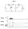
- FIG. 5 shows an example of a power supply device for electric discharge machining arranged to limit a charging current to the capacitor using an inductor.
- an inductor L is connected in place of the resistor R in the power supply device shown in FIG. 3.
- a diode D is connected in a reverse direction to be parallel with a series of direct-current power source E and a first switching element SW1.
- this power supply device is the same as the power supply device shown in FIG. 3.
- FIGS. 6a to 6c are operation timing charts in this power supply device for electric discharge machining until the capacitor C is charged.
- the first switching element SW1 When the first switching element SW1 is turned on (FIG. 6a), a current from the direct-current power source E flows through a closed loop comprising the first switching element SW1, the inductor L, the capacitor C and the direct-current power source E to charge the capacitor C, so that the voltage Vc of the capacitor increases as shown in FIG. 6c.
- the first switching element SW1 is turned off, a current Id produced by energy stored in the inductor L flows through the diode D as shown in FIG. 6b to further charge the capacitor C.
- a current Id produced by energy stored in the inductor L flows from the capacitor C, through the diode D, and then through the inductor L to charge the capacitor C, so that the voltage Vc of the capacitor further increases. Then, the second switching element SW2 is turned on to apply the voltage Vc of the capacitor between the electrode P and a workpiece W to cause electric discharge in between to perform machining.
- the power supply device for electric discharge machining which limits a charging current using an inductor as shown in FIG. 5 hardly produces energy loss, and therefore it can be called an efficient power supply device for electric discharge machining.
- a current produced by energy stored in the inductor flows and charges the capacitor.
- the present invention provides a power supply device for electric discharge machining in which energy loss is hardly produced and a charge voltage of a capacitor is easily controlled.
- a power supply device of the present invention supplies electrical energy between a workpiece and an electrode for performing electric discharge machining.
- the power supply device comprises: a capacitor for storing the electric energy for the electric discharge machining; a charging circuit including a direct-current power source, a switching element and an inductor connected in series to charge the capacitor; a first diode connected in a reverse direction to be parallel with the series connection of the direct-current power source and the switching element; and a second diode connected in a reverse direction to be parallel with the series connection of the switching element and the inductor.
- the power supply device comprises: a capacitor for storing the electrical energy for the electric discharge machining; a direct-current power source; a first switching element to be turned ON for charging the capacitor with electrical energy from the direct-current power source; a second switching element to be turned ON for discharging the electrical energy charged in the capacitor after the first switching element is turned OFF; the direct-current power source, the first switching element, an inductor, the second switching element, a gap between the electrode and the workpiece being connected in series, and the capacitor being connected in parallel with the series connection of the second switching element and the gap between the electrode and the workpiece, a first diode connected in parallel with the series connection of the direct-current power source and the first switching element; and a second diode connected in parallel with the series connection of the first switching element and the inductor.
- the charging circuit for charging the capacitor does not include a resistor, so that energy loss is hardly produced. Further, electric energy stored in the inductor is returned to the power source. In this respect, energy loss is removed. Further, since the charge voltage of the capacitor (voltage to be applied between the electrode and a workpiece) is kept at the direct-current power source voltage, the charge voltage of the capacitor can be controlled to be a desired value by adjusting the power source voltage.
- Direct-current power source E a first switching element (transistor) SW1, an inductor L, a second switching element (transistor) SW2, an electrode P as one pole and a workpiece W as the other pole are connected in series.
- a capacitor C is connected between the second switching element (transistor) SW2 and the electrode P and workpiece W as the two poles to be in parallel.
- the capacitor C is connected in parallel with the series of the second switching element (transistor) SW2 and the electrode P and workpiece W as the two poles.
- a first diode D1 is connected in a reverse direction between the direct-current power source E and the first switching element SW1 to be parallel with the series of the direct-current power source E and the first switching element SW1.
- the present embodiment is the same as the conventional electric-discharge-machining power supply device using an inductor shown in FIG. 5.
- a difference between this embodiment and the conventional power supply device for electric discharge machining is that a second diode D2 is connected between the first switching element SW1 and the inductor L to be parallel with the series of the first switching element SW1 and the inductor L.
- the second diode D2 is connected such that a direction from a point of connection with the capacitor C to a point of connection with the direct-current power source E is a forward direction of the diode D2.
- FIGS. 2a to 2d are operation timing charts in this power supply device for electric discharge machining until the capacitor is charged.
- the capacitor C is charged from the direct-current power source E via the first switching element SW1 and the inductor L, as shown in FIG. 2d.
- the voltage Vc of the capacitor C exceeds the power source voltage
- the second diode D2 becomes conductive, so that a current, which was flowing to the inductor L, flows through the diode D2 and the switching element SW1 and does not flow to the capacitor C, as shown in FIG. 2b.
- the voltage Vc of the capacitor C is kept at the power source voltage as shown in FIG. 2d.
- the present embodiment is the same as the conventional device.
- the charging circuit for the capacitor C does not include a resistor, so that energy loss caused by a resistor is removed. Energy loss is also prevented by returning the energy stored in the inductor L during charging to the direct-current power source E. Further, the voltage of the charged capacitor C is kept at the power source voltage. Hence, by adjusting the power source voltage, a desired voltage of the capacitor C can be obtained, irrespective of the ON-time of the switching element for charging. Thus, the charge voltage of the capacitor (voltage applied between the electrode and a workpiece) can be controlled accurately.
Landscapes
- Engineering & Computer Science (AREA)
- Mechanical Engineering (AREA)
- Chemical & Material Sciences (AREA)
- Chemical Kinetics & Catalysis (AREA)
- Electrochemistry (AREA)
- Electrical Discharge Machining, Electrochemical Machining, And Combined Machining (AREA)
Abstract
Description
Claims (2)
- A power supply device for supplying electrical energy between a workpiece and an electrode for performing electric discharge machining, comprising:a capacitor for storing the electric energy for the electric discharge machining;a charging circuit including a direct-current power source, a switching element and an inductor connected in series to charge said capacitor;a first diode connected in a reverse direction to be parallel with the series connection of the direct-current power source and the switching element; anda second diode connected in a reverse direction to be parallel with the series connection of the switching element and the inductor.
- A power supply device for supplying electrical energy between a workpiece and an electrode for electric discharge machining, comprising:a capacitor for storing the electrical energy for the electric discharge machining;a direct-current power source;a first switching element to be turned ON for charging said capacitor with electrical energy from said direct-current power source;a second switching element to be turned ON for discharging the electrical energy charged in the capacitor after said first switching element is turned OFF;said direct-current power source, said first switching element, an inductor, said second switching element, a gap between the electrode and the workpiece being connected in series, and said capacitor being connected in parallel with the series connection of the second switching element and the gap between the electrode and the workpiece,a first diode connected in parallel with the series connection of the direct-current power source and said first switching element; anda second diode connected in parallel with the series connection of said first switching element and the inductor.
Applications Claiming Priority (2)
| Application Number | Priority Date | Filing Date | Title |
|---|---|---|---|
| JP2004060868A JP2005246551A (en) | 2004-03-04 | 2004-03-04 | Power supply apparatus for electric discharge machining |
| JP2004060868 | 2004-03-04 |
Publications (2)
| Publication Number | Publication Date |
|---|---|
| EP1579940A2 true EP1579940A2 (en) | 2005-09-28 |
| EP1579940A3 EP1579940A3 (en) | 2006-08-16 |
Family
ID=34858320
Family Applications (1)
| Application Number | Title | Priority Date | Filing Date |
|---|---|---|---|
| EP05251220A Withdrawn EP1579940A3 (en) | 2004-03-04 | 2005-03-01 | Power supply device for electric discharge machining |
Country Status (4)
| Country | Link |
|---|---|
| US (1) | US7148442B2 (en) |
| EP (1) | EP1579940A3 (en) |
| JP (1) | JP2005246551A (en) |
| CN (1) | CN1663723A (en) |
Families Citing this family (15)
| Publication number | Priority date | Publication date | Assignee | Title |
|---|---|---|---|---|
| KR100818519B1 (en) * | 2006-05-04 | 2008-03-31 | 주식회사 엘지화학 | Battery care methods and devices |
| CN101767229B (en) * | 2008-12-30 | 2012-04-25 | 财团法人工业技术研究院 | Energy-saving discharge power supply for electric discharge processing machine |
| US9588532B2 (en) * | 2012-03-26 | 2017-03-07 | Infineon Technologies Americas Corp. | Voltage regulator having an emulated ripple generator |
| US10512979B2 (en) * | 2013-04-04 | 2019-12-24 | Seibu Electric & Machinery Co., Ltd. | Electrical discharge machining device, electrical discharge machining method, and design method |
| CN103464844B (en) * | 2013-09-26 | 2015-07-29 | 苏州群伦精密机电工业有限公司 | A kind of electric discharge processing circuit |
| JP5800923B2 (en) | 2014-01-15 | 2015-10-28 | ファナック株式会社 | Power supply device for wire electric discharge machine |
| JP5887378B2 (en) | 2014-04-30 | 2016-03-16 | ファナック株式会社 | Machining power supply device for electrical discharge machine |
| US10193442B2 (en) | 2016-02-09 | 2019-01-29 | Faraday Semi, LLC | Chip embedded power converters |
| CN111903019A (en) * | 2018-05-18 | 2020-11-06 | 海拉有限双合股份公司 | Driver circuit for a laser diode and circuit arrangement having such a driver circuit and a laser diode |
| CN110797925B (en) * | 2018-08-01 | 2021-08-03 | Oppo广东移动通信有限公司 | Battery control system and method, electronic device |
| US10504848B1 (en) | 2019-02-19 | 2019-12-10 | Faraday Semi, Inc. | Chip embedded integrated voltage regulator |
| WO2020214857A1 (en) | 2019-04-17 | 2020-10-22 | Faraday Semi, Inc. | Electrical devices and methods of manufacture |
| US11063516B1 (en) | 2020-07-29 | 2021-07-13 | Faraday Semi, Inc. | Power converters with bootstrap |
| US11990839B2 (en) | 2022-06-21 | 2024-05-21 | Faraday Semi, Inc. | Power converters with large duty cycles |
| US20250392207A1 (en) * | 2024-06-24 | 2025-12-25 | Honeywell International Inc. | Active pre-charge circuit for avionics lrus |
Family Cites Families (11)
| Publication number | Priority date | Publication date | Assignee | Title |
|---|---|---|---|---|
| US3832510A (en) * | 1972-06-16 | 1974-08-27 | Charmilles Sa Ateliers | Pulse generator for edm machine |
| JPS60180718A (en) * | 1984-02-29 | 1985-09-14 | Fanuc Ltd | Discharge machining power supply |
| JPH01153220A (en) * | 1987-12-08 | 1989-06-15 | Mitsubishi Electric Corp | Power source for electrospark machining |
| JPH01210219A (en) | 1988-02-19 | 1989-08-23 | Nec Corp | Electric discharge machining electric current control circuit |
| JP2591284B2 (en) * | 1990-08-24 | 1997-03-19 | 三菱電機株式会社 | Electric discharge machine |
| JPH06110544A (en) | 1992-09-25 | 1994-04-22 | Mitsubishi Heavy Ind Ltd | Remote manipulator for robot |
| JP2914103B2 (en) * | 1993-06-30 | 1999-06-28 | 三菱電機株式会社 | Electric discharge machine |
| JP3381359B2 (en) * | 1994-02-25 | 2003-02-24 | 三菱電機株式会社 | Power supply unit for electric discharge machine |
| US6366063B1 (en) * | 2000-03-22 | 2002-04-02 | Nec Corporation | Circuit and method for driving capacitive load |
| JP2002172575A (en) | 2000-12-07 | 2002-06-18 | Fanuc Ltd | Teaching device |
| JP2003189602A (en) * | 2001-12-17 | 2003-07-04 | Murata Mfg Co Ltd | Dc-dc converter and electric equipment using the same |
-
2004
- 2004-03-04 JP JP2004060868A patent/JP2005246551A/en active Pending
-
2005
- 2005-03-01 EP EP05251220A patent/EP1579940A3/en not_active Withdrawn
- 2005-03-02 US US11/068,845 patent/US7148442B2/en not_active Expired - Fee Related
- 2005-03-03 CN CN2005100510753A patent/CN1663723A/en active Pending
Also Published As
| Publication number | Publication date |
|---|---|
| US7148442B2 (en) | 2006-12-12 |
| EP1579940A3 (en) | 2006-08-16 |
| JP2005246551A (en) | 2005-09-15 |
| US20050194947A1 (en) | 2005-09-08 |
| CN1663723A (en) | 2005-09-07 |
Similar Documents
| Publication | Publication Date | Title |
|---|---|---|
| US7148442B2 (en) | Power supply device for electric discharge machining | |
| KR920005353B1 (en) | Pulse generator for spark-erosive metal working | |
| US10730126B2 (en) | Power supply device for wire electric discharge machining | |
| US7839128B2 (en) | Bidirectional power supply device | |
| US6900620B2 (en) | Switching regulator having two or more outputs | |
| TWI435522B (en) | Charge pump controller and method therefor | |
| US6660957B1 (en) | Apparatus for electric discharge machining | |
| EP0174372B1 (en) | Power source for electric discharge machining | |
| US6707275B2 (en) | Automative generator control apparatus | |
| TWI233408B (en) | Charging apparatus of bicycle dynamo | |
| JP2010522839A (en) | Drive control circuit and drive control method for piezoelectric element | |
| JP4712081B2 (en) | Charging circuit and charging circuit control method | |
| JP2007159310A (en) | Power supply | |
| US6844517B2 (en) | Power supply device for electric discharge machine | |
| WO2005102578A1 (en) | Discharge processing machine power supply apparatus and power supply control method | |
| WO2005091497A1 (en) | Switch mode power supply with output voltage equalizer | |
| KR20030094090A (en) | Device for machining by electroerosion | |
| CN114268225A (en) | Voltage regulation circuit and method of switching power supply and power supply system | |
| JP2004106130A (en) | Pulse power supply device | |
| JP3381359B2 (en) | Power supply unit for electric discharge machine | |
| WO2021005894A1 (en) | Dc-dc converter and power supply device | |
| US20060232242A1 (en) | Charging apparatus | |
| JP4099090B2 (en) | Power supply device and method of operating power supply device | |
| SU1632663A1 (en) | Pulse generator for electrical discharge machining | |
| JPS62287911A (en) | Power source for electric discharge machining |
Legal Events
| Date | Code | Title | Description |
|---|---|---|---|
| PUAI | Public reference made under article 153(3) epc to a published international application that has entered the european phase |
Free format text: ORIGINAL CODE: 0009012 |
|
| AK | Designated contracting states |
Kind code of ref document: A2 Designated state(s): AT BE BG CH CY CZ DE DK EE ES FI FR GB GR HU IE IS IT LI LT LU MC NL PL PT RO SE SI SK TR |
|
| AX | Request for extension of the european patent |
Extension state: AL BA HR LV MK YU |
|
| PUAL | Search report despatched |
Free format text: ORIGINAL CODE: 0009013 |
|
| AK | Designated contracting states |
Kind code of ref document: A3 Designated state(s): AT BE BG CH CY CZ DE DK EE ES FI FR GB GR HU IE IS IT LI LT LU MC NL PL PT RO SE SI SK TR |
|
| AX | Request for extension of the european patent |
Extension state: AL BA HR LV MK YU |
|
| RIC1 | Information provided on ipc code assigned before grant |
Ipc: B23H 7/04 20060101ALI20060712BHEP Ipc: B23H 1/02 20060101AFI20050729BHEP |
|
| 17P | Request for examination filed |
Effective date: 20061206 |
|
| AKX | Designation fees paid |
Designated state(s): CH LI |
|
| REG | Reference to a national code |
Ref country code: DE Ref legal event code: 8566 |
|
| STAA | Information on the status of an ep patent application or granted ep patent |
Free format text: STATUS: THE APPLICATION HAS BEEN WITHDRAWN |
|
| 18W | Application withdrawn |
Effective date: 20070828 |