EP1579925A2 - Schnell zu montierende und demontierende Düse und deren Herstellungsverfahren - Google Patents
Schnell zu montierende und demontierende Düse und deren Herstellungsverfahren Download PDFInfo
- Publication number
- EP1579925A2 EP1579925A2 EP05102299A EP05102299A EP1579925A2 EP 1579925 A2 EP1579925 A2 EP 1579925A2 EP 05102299 A EP05102299 A EP 05102299A EP 05102299 A EP05102299 A EP 05102299A EP 1579925 A2 EP1579925 A2 EP 1579925A2
- Authority
- EP
- European Patent Office
- Prior art keywords
- fixing support
- locking means
- tip
- spraying tip
- spraying
- Prior art date
- Legal status (The legal status is an assumption and is not a legal conclusion. Google has not performed a legal analysis and makes no representation as to the accuracy of the status listed.)
- Withdrawn
Links
- 238000000034 method Methods 0.000 title claims abstract description 7
- 238000005507 spraying Methods 0.000 claims abstract description 43
- 238000003780 insertion Methods 0.000 claims abstract description 10
- 230000037431 insertion Effects 0.000 claims abstract description 9
- 238000004519 manufacturing process Methods 0.000 claims abstract description 6
- 230000002441 reversible effect Effects 0.000 claims abstract 2
- 230000000295 complement effect Effects 0.000 claims description 6
- 238000003754 machining Methods 0.000 claims description 5
- 238000007789 sealing Methods 0.000 claims description 3
- 239000013536 elastomeric material Substances 0.000 claims description 2
- 239000012858 resilient material Substances 0.000 claims 1
- 239000002184 metal Substances 0.000 description 5
- 210000002445 nipple Anatomy 0.000 description 4
- 239000000463 material Substances 0.000 description 3
- 239000007788 liquid Substances 0.000 description 2
- 238000005406 washing Methods 0.000 description 2
- 230000000903 blocking effect Effects 0.000 description 1
- 238000005266 casting Methods 0.000 description 1
- 230000008878 coupling Effects 0.000 description 1
- 238000010168 coupling process Methods 0.000 description 1
- 238000005859 coupling reaction Methods 0.000 description 1
- 230000007423 decrease Effects 0.000 description 1
- 238000005238 degreasing Methods 0.000 description 1
- 238000005242 forging Methods 0.000 description 1
- 238000007731 hot pressing Methods 0.000 description 1
- 239000012535 impurity Substances 0.000 description 1
- 238000012423 maintenance Methods 0.000 description 1
- 230000014759 maintenance of location Effects 0.000 description 1
- 238000012986 modification Methods 0.000 description 1
- 230000004048 modification Effects 0.000 description 1
- 238000000465 moulding Methods 0.000 description 1
- 238000010422 painting Methods 0.000 description 1
- 239000002245 particle Substances 0.000 description 1
- 238000005554 pickling Methods 0.000 description 1
- 238000003825 pressing Methods 0.000 description 1
- 238000002203 pretreatment Methods 0.000 description 1
- 239000007787 solid Substances 0.000 description 1
- 239000007921 spray Substances 0.000 description 1
- 235000013311 vegetables Nutrition 0.000 description 1
- XLYOFNOQVPJJNP-UHFFFAOYSA-N water Substances O XLYOFNOQVPJJNP-UHFFFAOYSA-N 0.000 description 1
Images


Classifications
-
- B—PERFORMING OPERATIONS; TRANSPORTING
- B05—SPRAYING OR ATOMISING IN GENERAL; APPLYING FLUENT MATERIALS TO SURFACES, IN GENERAL
- B05B—SPRAYING APPARATUS; ATOMISING APPARATUS; NOZZLES
- B05B15/00—Details of spraying plant or spraying apparatus not otherwise provided for; Accessories
- B05B15/60—Arrangements for mounting, supporting or holding spraying apparatus
- B05B15/65—Mounting arrangements for fluid connection of the spraying apparatus or its outlets to flow conduits
Definitions
- the present invention relates to a fast connection/disconnection nozzle and to the corresponding process for the making of the same.
- Fast connection/disconnection nozzles are nozzles in which a spraying tip can be quickly inserted and/or taken out from a fixing support with a precise and repeatable angular positioning with respect to the fixing support itself.
- Such kind of nozzles are used, for example, in plants for the pre-treatment prior to a painting step, or in plants for pickling, degreasing or phosphating of motor-vehicle bodies and parts of bodywork or parts of electrical household appliances made of metal sheets, or else in systems for washing purposes, e.g. for washing vegetables with water on a conveyor belt.
- the parts for the coupling that enable a fast connection/disconnection between the spraying tip and the corresponding support and the precise angular positioning thereof have shapes which in the case they are made of metal, such shapes they are not particularly suited to being made by machining operations involving removal of chips. In this case, such shapes render necessary or economically convenient operations of pre-forming and roughing by hot pressing or casting.
- the main object of the present invention is to provide a fast connection/disconnection nozzle that can be produced with machining operations which are more simplified and economically advantageous when compared to the nozzles of the state of the art.
- the invention provides a spraying tip and a fixing support according to claim 1.
- the invention provides a process for the production of said tip according to claim 21, and a process for the production of a fixing support according to claim 22.
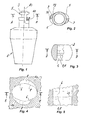
- the nozzle comprises a spraying tip 1 and a fixing support 2, the latter having an outer spherical shape.
- the fixing support 2 constitute a component of a ball joint for allowing a full orientation of the tip within the space.
- the spraying tip 1 is provided with a fixing end, which defines an oval engagement cam 3.
- the cam 3 has a shape such as to be introduced into the internal cavity 4 within the fixing support 2, and engaged thereto by means of a rotation of 1 ⁇ 4 of a turn about the axis of insertion AS, in order to clamp the spraying tip 1 onto the support 2 both axially and within a precise angular position with respect to said axis AS.
- the axis AS is the axis of symmetry of the spraying tip 1 and the relevant cam 3 thereof, and for the fixing support 2.
- the cam 3 comprises two first engaging surfaces 5 which are designed to abut a corresponding second engaging surfaces 6 within the fixing support 2, the second surfaces being substantially complementary to said first engaging surfaces 5 and having a curved and chamfered profile which is complementary to the profile of the first engaging surfaces 5.
- the profile of the first engaging surfaces 5 have a substantially curved and chamfered outer profile that is substantially without any sharp edges, therefore the same can be readily obtained or in any case easily machined, e.g. by means of a numeric-control lathe, saving costs and time.
- the engagement cam 3 when viewed from top plan has a substantially oval shape with two engagement lobes, which are chamfered and without any sharp edges. Said two lobes of the engagement cam 3 define two engagement projections, which extend radially with respect to the axis AS and enable the spraying tip 1 to be withheld axially with respect to the fixing support 2 when inserted therein.
- the engagement cam 3 is shaped so as to be slid through an oval opening 7 with transverse walls 8 obtained at the internal cavity 4 within said fixing support 2.
- the bottom surfaces of the lobes of the engaging cam 3 have each a sloped surface 9 so that they show a thickness that decreases from point P1 to point P2.
- the transverse walls 8 each have an area 10 with a thickness that increases in the direction of disengagement of the cam. Further, underlying the transverse wall 8 there is provided an inclined surface 12 which when engaged with the cam 3 tends to rotate the latter with a counterclockwise rotation (as viewed in Figure 4) and abut the latter onto said second engaging surface 6.
- the lead-in surface 12 can be replaced by a step shaped as a tooth 13 or a projection in an axial direction so as to provide appropriate blocking means from rotate the cam 3 of the spraying tip 1 when inserted therein.
- the spraying tip 1 is further provided with an annular gasket 11 or other elastic means having both the sealing function and elastic function for biasing the engagement cam 3 against the two transverse walls 8 within the fixing support 2 and in the direction of the axis AS.
- the nozzle comprises a spraying tip 21, a fixing support 22, and a tubular gasket 20.
- the fixing support 22 has the shape of an externally threaded nipple.
- the tubular gasket 20 is inserted into a top cavity 23 within the fixing support 22.
- the spraying tip 21 is provided with a first engagement cam 24 and a second engagement cam 24' positioned within a preset distance one from the other.
- both cams 24 and 24' have surfaces having a substantially curved and chamfered outer profile without sharp edges, and when viewed in top plan (direction of arrow C in figure 8) they have an oval profile with two lobes.
- bottom surfaces 29 and 29' of both cams 24 and 24' may be completely horizontal with respect to the longitudinal direction of said axis AS, e.g. they are not sloped.
- the gasket 20 has internally thereof two second engaging surfaces 26 and two radial engaging projections 25 which are made of a wall of rubber or elastomeric material.
- the engaging projection 25 are radially resilient and projects in a direction which is normal to the axis of insertion AS and towards the inside of the gasket.
- the spraying tip 21 is first inserted into the fixing support 22 through the gasket 20, the first engagement cam 24 passing through the oval opening 27 of the support 22. Then, by rotating the spraying tip 21 in a counter-clockwise direction (as viewed in Figure 11), the first cam 24 will underlay the transverse wall 28 of the nipple 22 engaging the same and the axial sliding of the tip 21 from the nipple 22 being prevented, whilst the second cam 24' passes beyond the two retention projections 25 deforming the latter and abut the surfaces 26. In this condition, the tip 21 results in being blocked in a defined angular position with respect to the nipple 22.
- tubular gasket 20 is shaped in such a way as to press the bottom surfaces 29 of the cam 24 against the transverse wall 28 in the axial direction along axis AS.
- the tubular gasket 20 can be reversibly inserted into and removed from the fixing support 22.
- This arrangement has the advantage of enabling a replacement of the same at a very contained costs when needed, e.g. when the gasket shows incrustations or is worn out, given that this type of nozzle is frequently used for spraying liquids that contain particles and other solid impurities, or else viscous liquids.
- gasket 20 can be advantageously replaced without having to dismantle/reassemble the fixing support 22.
- the oval shape of the two cams 24 and 24' allows an easy and convenient production of the same by a numeric control lathe.
- the nozzles described above may be realised with all of the parts which constitute the same made of the same material, e.g. metal or plastic or similar, or with the spraying tip 1 or 21 made of metal and the fixing support 2 or 22 made of plastic material, or vice versa.
- nozzles are suitable to be produced with extensive use of machining operation at relatively contained costs, both in the case they are to be made of metal or of plastic material, instead of the nozzles of the state of the art where there is needed forming operations of pressing, or moulding, or forging.
Landscapes
- Nozzles (AREA)
- On-Site Construction Work That Accompanies The Preparation And Application Of Concrete (AREA)
- Catching Or Destruction (AREA)
Applications Claiming Priority (2)
| Application Number | Priority Date | Filing Date | Title |
|---|---|---|---|
| IT000541A ITMI20040541A1 (it) | 2004-03-22 | 2004-03-22 | Ugello a rapida connessione-sconnessione e relativo metodo di riproduzione |
| ITMI20040541 | 2004-03-22 |
Publications (2)
| Publication Number | Publication Date |
|---|---|
| EP1579925A2 true EP1579925A2 (de) | 2005-09-28 |
| EP1579925A3 EP1579925A3 (de) | 2008-04-02 |
Family
ID=34856921
Family Applications (1)
| Application Number | Title | Priority Date | Filing Date |
|---|---|---|---|
| EP05102299A Withdrawn EP1579925A3 (de) | 2004-03-22 | 2005-03-22 | Schnell zu montierende und demontierende Düse und deren Herstellungsverfahren |
Country Status (2)
| Country | Link |
|---|---|
| EP (1) | EP1579925A3 (de) |
| IT (1) | ITMI20040541A1 (de) |
Families Citing this family (1)
| Publication number | Priority date | Publication date | Assignee | Title |
|---|---|---|---|---|
| ITUA20161714A1 (it) | 2016-03-16 | 2017-09-16 | Pnr Italia S R L | Guarnizione di tenuta avente un foro passante a sezione trasversale di ampiezza decrescente, ugello accoppiabile a detta guarnizione e terminale di spruzzatura comprendente detto ugello accoppiato a detta guarnizione |
Citations (2)
| Publication number | Priority date | Publication date | Assignee | Title |
|---|---|---|---|---|
| US4438884A (en) | 1981-11-02 | 1984-03-27 | Spraying Systems Company | Quick disconnect nozzle |
| EP0450946A2 (de) | 1990-04-05 | 1991-10-09 | Spraying Systems Co. | Rasch zerlegbarer Düsenaufbau |
Family Cites Families (1)
| Publication number | Priority date | Publication date | Assignee | Title |
|---|---|---|---|---|
| GB9021385D0 (en) * | 1990-10-02 | 1990-11-14 | Asbury Anthony J | Advanced connectors |
-
2004
- 2004-03-22 IT IT000541A patent/ITMI20040541A1/it unknown
-
2005
- 2005-03-22 EP EP05102299A patent/EP1579925A3/de not_active Withdrawn
Patent Citations (2)
| Publication number | Priority date | Publication date | Assignee | Title |
|---|---|---|---|---|
| US4438884A (en) | 1981-11-02 | 1984-03-27 | Spraying Systems Company | Quick disconnect nozzle |
| EP0450946A2 (de) | 1990-04-05 | 1991-10-09 | Spraying Systems Co. | Rasch zerlegbarer Düsenaufbau |
Also Published As
| Publication number | Publication date |
|---|---|
| ITMI20040541A1 (it) | 2004-06-22 |
| EP1579925A3 (de) | 2008-04-02 |
Similar Documents
| Publication | Publication Date | Title |
|---|---|---|
| US20240075484A1 (en) | Spray head | |
| JP6283157B2 (ja) | 切削工具 | |
| RU2429077C2 (ru) | Душевая насадка | |
| EP0482369B1 (de) | Düse | |
| JP3181358U (ja) | 内燃機関用のピストン | |
| CN106090471B (zh) | 管道配件装置的止动环制造方法及其止动环 | |
| KR20100105842A (ko) | 열분사 코팅에 의한 피스톤 링의 측부 보호 | |
| US20160131170A1 (en) | Screw drive | |
| CA2922030A1 (en) | Flat jet nozzle, and use of a flat jet nozzle | |
| JPH11148509A5 (de) | ||
| KR20190086484A (ko) | 척 | |
| CN106903418B (zh) | 分体式多刀刃修磨刀具单元 | |
| CN106861964A (zh) | 一种喷枪及清洗设备 | |
| EP1579925A2 (de) | Schnell zu montierende und demontierende Düse und deren Herstellungsverfahren | |
| US12251719B2 (en) | Nozzle assembly for delivering an oscillating spray pattern | |
| KR101809696B1 (ko) | 피스톤 링 생산 방법 | |
| US11808295B2 (en) | Fixing device | |
| US4706889A (en) | Spray-shower with nozzles, particularly flat fan nozzles | |
| EP3359315A1 (de) | Spiralwerkzeugverriegelungssystem | |
| CN202290373U (zh) | 高压清洗机用的旋转清洗平面的喷嘴 | |
| JP2023506686A (ja) | 電子膨張弁のナット座構造及びその取り付け方法 | |
| US11585304B2 (en) | Rail for high-pressure direct injection | |
| JP2009541703A5 (de) | ||
| US10480567B2 (en) | Ball element with retracting stud | |
| JP2015073930A (ja) | 洗浄ターゲット |
Legal Events
| Date | Code | Title | Description |
|---|---|---|---|
| PUAI | Public reference made under article 153(3) epc to a published international application that has entered the european phase |
Free format text: ORIGINAL CODE: 0009012 |
|
| AK | Designated contracting states |
Kind code of ref document: A2 Designated state(s): AT BE BG CH CY CZ DE DK EE ES FI FR GB GR HU IE IS IT LI LT LU MC NL PL PT RO SE SI SK TR |
|
| AX | Request for extension of the european patent |
Extension state: AL BA HR LV MK YU |
|
| PUAL | Search report despatched |
Free format text: ORIGINAL CODE: 0009013 |
|
| AK | Designated contracting states |
Kind code of ref document: A3 Designated state(s): AT BE BG CH CY CZ DE DK EE ES FI FR GB GR HU IE IS IT LI LT LU MC NL PL PT RO SE SI SK TR |
|
| AX | Request for extension of the european patent |
Extension state: AL BA HR LV MK YU |
|
| 17P | Request for examination filed |
Effective date: 20080930 |
|
| AKX | Designation fees paid |
Designated state(s): DE FR GB IT |
|
| 17Q | First examination report despatched |
Effective date: 20091120 |
|
| STAA | Information on the status of an ep patent application or granted ep patent |
Free format text: STATUS: THE APPLICATION IS DEEMED TO BE WITHDRAWN |
|
| 18D | Application deemed to be withdrawn |
Effective date: 20100331 |