EP1579807A1 - Ultraschallabbildungssystem - Google Patents
Ultraschallabbildungssystem Download PDFInfo
- Publication number
- EP1579807A1 EP1579807A1 EP05005958A EP05005958A EP1579807A1 EP 1579807 A1 EP1579807 A1 EP 1579807A1 EP 05005958 A EP05005958 A EP 05005958A EP 05005958 A EP05005958 A EP 05005958A EP 1579807 A1 EP1579807 A1 EP 1579807A1
- Authority
- EP
- European Patent Office
- Prior art keywords
- ultrasonic
- intravascular
- temperature
- transducer
- blood vessel
- Prior art date
- Legal status (The legal status is an assumption and is not a legal conclusion. Google has not performed a legal analysis and makes no representation as to the accuracy of the status listed.)
- Granted
Links
Images



Classifications
-
- A—HUMAN NECESSITIES
- A61—MEDICAL OR VETERINARY SCIENCE; HYGIENE
- A61B—DIAGNOSIS; SURGERY; IDENTIFICATION
- A61B8/00—Diagnosis using ultrasonic, sonic or infrasonic waves
- A61B8/12—Diagnosis using ultrasonic, sonic or infrasonic waves in body cavities or body tracts, e.g. by using catheters
-
- A—HUMAN NECESSITIES
- A61—MEDICAL OR VETERINARY SCIENCE; HYGIENE
- A61B—DIAGNOSIS; SURGERY; IDENTIFICATION
- A61B5/00—Measuring for diagnostic purposes; Identification of persons
- A61B5/01—Measuring temperature of body parts ; Diagnostic temperature sensing, e.g. for malignant or inflamed tissue
- A61B5/015—By temperature mapping of body part
-
- A—HUMAN NECESSITIES
- A61—MEDICAL OR VETERINARY SCIENCE; HYGIENE
- A61B—DIAGNOSIS; SURGERY; IDENTIFICATION
- A61B8/00—Diagnosis using ultrasonic, sonic or infrasonic waves
- A61B8/44—Constructional features of the ultrasonic, sonic or infrasonic diagnostic device
- A61B8/4416—Constructional features of the ultrasonic, sonic or infrasonic diagnostic device related to combined acquisition of different diagnostic modalities, e.g. combination of ultrasound and X-ray acquisitions
Definitions
- Ultrasonic diagnostic imaging apparatus for use in body cavities generally have an ultrasonic catheter for scanning a body vessel such as a blood vessel or a vessel.
- the ultrasonic catheter also has a priming through hole 6 defined in the distal end portion thereof for removing air from the catheter tube 2 when the catheter tube 2 is filled up with a normal saline solution.
- the catheter tube 2 houses therein an X-ray marker 7 in the form of a metal coil.
- the X-ray marker 7 also serves as a stiffener for preventing the ultrasonic catheter from being bent.
- the ultrasonic transducer 9 While the drive shaft 11 is being rotated by the motor, the ultrasonic transducer 9 emits and receives ultrasonic waves reflected from the inner wall of the blood vessel in all directions (360°) for generating a tomographic image of the blood vessel.
- Japanese patent publication No. Hei 7-38852 discloses an ultrasonic probe for sending and receiving ultrasonic waves to acquire a tomographic image of the blood vessel, and introducing the blood from the blood vessel and measuring the temperature of the introduced blood with a temperature sensor. That disclosed ultrasonic probe can detect the temperature of the blood, as well as a tomographic image of the blood vessel like the ultrasonic catheter shown in FIG. 1, for diagnostic purposes.
- the distal end portion 1 of the ultrasonic catheter shown in FIG. 1 has only the ultrasonic transducer 9 and is unable to detect the temperature in the blood vessel in a particular location in the living body.
- the ultrasonic probe disclosed in Japanese patent publication No. Hei 7-38852 suggests that an ultrasonic tomographic image is displayed on a display unit such as a display monitor or the like. However, it fails to disclose anything about how the temperature information of the blood that is measured by the temperature sensor is used, and about how the temperature information is visually presented. It can only be guessed from the disclosed ultrasonic probe that a numerical value of the temperature information may be displayed together with the ultrasonic tomographic image.
- the intravascular ultrasonic device to measure the intravascular temperature or the temperature of an arteriosclerotic plaque to predict the possibility of an arterial sclerosis. It has been reported that when an arteriosclerotic plaque, though not clearly confirmed by an image, is formed in an arterial coronaria, the intravascular temperature is 0.11 ⁇ 0.11°C higher than the normal intravascular temperature when the patient is suffering stable angina, 0.68 ⁇ 0.35°C higher than the normal intravascular temperature when the patient is suffering unstable angina, and 1.47 ⁇ 0.69°C higher than the normal intravascular temperature when the patient is suffering acute myocardial infarction.
- An intravascular ultrasonic diagnostic imaging apparatus has a catheter with an ultrasonic transducer incorporated therein.
- the catheter is inserted into a blood vessel, and the ultrasonic transducer in the catheter is rotated to perform radial scanning on the blood vessel. Based on reflected ultrasonic waves, the intravascular ultrasonic diagnostic imaging apparatus displays a tomographic image of the blood vessel on a display monitor.
- the above two conventional devices need to produce an ultrasonic intravascular tomographic image and measure a temperature separately. Therefore it cannot accurately identify where each of the temperature data is measured in the blood vessel or where there is the plaque because the location where the temperature is measured cannot be specified.
- an ultrasonic imaging system comprising an ultrasonic catheter including an insert for being inserted into a blood vessel, a transducer disposed in the insert, and at least one temperature sensor disposed in the insert, wherein said transducer and said temperature sensor scan the blood vessel in a direction which is perpendicular or parallel to a longitudinal axis of the blood vessel, and said transducer provides a tomographic vascular image of the blood vessel, and said temperature sensor measures an intravascular temperature distribution in the blood vessel.
- the temperature sensor may be disposed in the same position as the transducer in a longitudinal direction of the insert.
- said transducer has a front side which sends and/or receives an ultrasonic signal and a rear side, and said temperature sensor is mounted a position of the rear side of said transducer.
- the ultrasonic catheter may further include a guide wire lumen and a priming hole defined in a junction between the guide wire lumen and a distal end portion of the ultrasonic catheter.
- a diagnostic imaging system including the ultrasonic catheter and a diagnostic imaging apparatus including an ultrasonic signal receiver for receiving an ultrasonic signal measured by the transducer, a temperature signal receiver for receiving an intravascular temperature signal measured by the temperature sensor, and an image constructing unit for constructing an image to be displayed from a tomographic vascular image generated from the ultrasonic signal and intravascular temperature information generated from the intravascular temperature signal, in relation to positional information of the ultrasonic signal and the intravascular temperature signal.
- the temperature sensor may be disposed in the same position as the transducer in a longitudinal direction of the insert.
- the display unit may display a pattern diagram of the blood vessel having a plurality of divided regions with an average value of said intravascular temperature information in association with each of said divided regions.
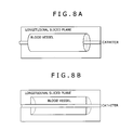
- the temperature sensor and the transducer may be translated in the insert about a longitudinal axis of the blood vessel, and the ultrasonic signal receiver and the temperature signal receiver may receive an ultrasonic signal representative of an intravascular ultrasonic longitudinal tomographic image and an intravascular temperature signal representative of intravascular longitudinal temperature information, respectively.
- the temperature sensor and the transducer are being moved, and wherein the display unit simultaneously displays the intravascular ultrasonic longitudinal tomographic image and the intravascular longitudinal temperature information in synchronism with the movement of the temperature sensor and the transducer.
- the display unit may display the intravascular ultrasonic longitudinal tomographic image and the intravascular longitudinal temperature information in superimposed relation to each other.
- the ultrasonic catheter is capable of simultaneously generating an intravascular tomographic image and measuring an intravascular temperature at a particular location in a living body, and of identifying a measured location in a living body.
- the ultrasonic intravascular diagnostic imaging apparatus has such an ultrasonic catheter and is capable of simultaneously visually displaying a generated tomographic image and a measured intravascular temperature.
- FIG. 2 shows an entire ultrasonic catheter 100 according to the present invention.
- the ultrasonic catheter 100 includes a sheath 200 serving as an insert to be inserted into a blood vessel and a hub 300 to be manually handled by the user.
- the hub 300 is positioned at a proximal end of the sheath 200 and not inserted into the blood vessel.
- the sheath 200 has a sheath distal end portion 210 (see FIG. 3), a tubular sheath body 220, and an intermediate sheath portion 230.
- the sheath distal end portion 210 and the sheath body 220 are interconnected by the intermediate sheath portion 230.
- the sheath body 220 is connected to the hub 300.
- the sheath distal end portion 210 has an X-ray marker 240 for giving a visual indication as to the location of the ultrasonic catheter 100 in the living body in an X-ray radioscopic image when the ultrasonic catheter 100 inserted into a blood vessel.
- the sheath distal end portion 210 also has a guide wire lumen for the passage of a guide wire (GW) 250 therethrough.
- the guide wire 250 is inserted in the blood vessel in advance and used to guide the ultrasonic catheter 100 to a desired region in the living body.
- the ultrasonic catheter 100 is guided to the desired region by the guide wire 250 that extends through the guide wire lumen in the sheath distal end portion 210.
- the sheath body 220 is connected to the intermediate sheath portion 230 and the hub 300.
- the sheath distal end portion 210 has an outside diameter D1
- the intermediate sheath portion 230 has an outside diameter D2
- the sheath body 220 has an outside diameter D3.
- These outside diameters D1, D2, D3 are related to each other by D1 ⁇ D2 ⁇ D3.
- the outside diameter D1 is 0.80 mm
- the outside diameter D2 is 0.87 mm
- the outside diameter D3 is in the range from 1.04 to 1.06 mm.
- the imaging core 400 is housed in the sheath 200.
- the imaging core 400 includes: (i) a transducer unit 410 serving as an ultrasonic transducer for sending ultrasonic waves to a blood vessel tissue and receiving ultrasonic waves reflected from the blood vessel tissue, (ii) a temperature sensor 440 for detecting an intravascular temperature in the living body, (iii) a drive shaft 420 for rotating and translating the transducer unit 410 and the temperature sensor 440 which are mounted on a tip end thereof, and (iv) a metal coil 430 associated with the transducer unit 410.
- the imaging core 400 is rotatable and translatable about the sheath 200.
- sheath distal end portion 210 will be described in specific detail below with reference to FIG. 3.
- the sheath distal end portion 210 has a guide wire insertion tube 270 which provides a guide wire lumen therein.
- the guide wire 250 has its rear end inserted into the guide wire insertion tube 270, and extends through the guide wire insertion tube 270. The guide wire 250 thus inserted guides the ultrasonic catheter 100 to a desired position in the living body.
- the imaging core 400 includes the transducer unit 410 for sending and receiving ultrasonic waves and the temperature sensor 440 for detecting temperatures in body cavities (blood vessels and vessels).
- the transducer unit 410 and the temperature sensor 440 have a size of about 1 mm each, and are disposed in a single housing 450.
- the transducer unit 410 has a front side which sends and receives an ultrasonic signal and a rear side.
- the temperature sensor 440 is mounted in the housing 450 at the 180-degree opposite side (rear side) of the transducer unit 410.
- the imaging core 400 may have one or more temperature sensors 440 which may be positioned alongside of the transducer unit 410 or juxtaposed, rather than behind the transducer unit 410.
- the imaging core 400 may also have a plurality of transducer units 410.
- the transducer unit 410 and the temperature sensor 440 are rotated thereby to observe a desired region in a body cavity such as a blood vessel or a vessel in an angular range of 360°.
- the transducer unit 410 for sending and receiving ultrasonic waves and the temperature sensor 440 for detecting temperatures in blood vessel are disposed in the sheath distal end portion 210 for simultaneously acquiring both information for generating an ultrasonic tomographic image and temperature information in the blood vessel.
- the temperature detected by the temperature sensor 440 is a temperature of a blood vessel wall temperature that transmits the blood and the wall of the catheter sheath tube 290.
- the transducer unit 410 and the temperature sensor 440 are disposed in the same location with respect to the longitudinal direction of the imaging core 400, i.e., the scanning direction of the ultrasonic catheter 100.
- the transducer unit 410 and the temperature sensor 440 are disposed in confronting relation to each other along the longitudinal direction of the imaging core 400.
- the transducer unit 410 is also disposed in the same location as the temperature sensors with respect to the longitudinal direction of the imaging core 400. According to this layout, an ultrasonic tomographic image and temperature information of one location in the living body can simultaneously be acquired. Therefore, the image information and the temperature information can easily be combined into a combined image when both are displayed on a display screen, as described later.
- the transducer unit 410 and the temperature sensor 440 were instead disposed in different respective locations with respect to the longitudinal direction of the imaging core 400, then it would be necessary to calculate which temperature information corresponds to which ultrasonic tomographic image from the distances up to the transducer unit 410 and the temperature sensor 440 in order to synchronize the ultrasonic tomographic image and the temperature information with each other.
- the imaging core 400 or the catheter when the imaging core 400 or the catheter is pulled 5 mm from outside of the living body, it is not certain whether the transducer and the temperature sensor move equally 5 mm within the living body. Since the imaging core 400 or the catheter is usually inserted through an arm or a thigh of the patient, it is bent many times before it reaches the heart. Therefore, no one is sure as to whether the transducer and the sensor move equally 5 mm within the living body. In addition, after a certain region such as a region with a plaque is detected by an IVUS (IntraVascular UltraSonic) image, the imaging core 400 or the catheter is moved to cause the temperature sensor to reach that region. However, it is very difficult to accurately move the imaging core 400 or the catheter. These problems can be solved by simultaneously acquiring the ultrasonic tomographic image and the temperature information in accordance with the present invention.
- IVUS Intrascular UltraSonic
- the imaging core 400 itself can be reduced in size. With the imaging core 400 reduced in size, the ultrasonic catheter 100 may be made thinner for easy insertion through bent passages.
- the metal coil 430 is disposed in a distal end portion of the imaging core 400.
- the metal coil 430 is used as an X-ray marker and also serves to prevent a catheter tube 290 made of polyethylene, for example, whose outside diameter is 1.0 mm and inside diameter is 0.85 mm, from being bent.
- the sheath distal end portion 210 has a priming hole 280.
- an ultrasonic transfer medium such as a normal saline solution
- an excess of the ultrasonic transfer medium is removed from the priming hole 280 so that the space around imaging core 400 is filled up with the ultrasonic transfer medium.
- the priming hole 280 is much narrower than the conventional priming hole for minimizing any backward flow of the blood into the catheter tube 290.
- the ultrasonic transfer medium is primed through the priming hole 280 in each cycle of producing an ultrasonic tomographic image and measuring the temperature. Therefore, bubbles trapped around the transducer unit 410 can be removed for more accurate measurement. Though the temperature sharply drops when the ultrasonic transfer medium is primed, the temperature immediately rises up to the normal level.
- FIG. 4 shows in block form an intravascular ultrasonic diagnostic imaging apparatus 500 for processing ultrasonic data and temperature data detected by the ultrasonic catheter 100.
- an ultrasonic signal received by the transducer unit 410 is amplified, logarithmically converted, and detected by an ultrasonic signal transmitter/receiver 510, and then sent to an image constructing unit 550.
- the image constructing unit 550 converts the ultrasonic signal into a digital ultrasonic signal and constructs an image from the digital ultrasonic signal.
- a display unit 560 displays the image constructed by the image constructing unit 550.
- a temperature signal detected by the temperature sensor 440 is amplified, corrected, and converted in voltage by a temperature signal receiver 530, and then sent to the image constructing unit 550.
- the image constructing unit 550 converts the temperature represented by the temperature signal and constructs a temperature image from the temperature signal.
- the display unit 560 displays the temperature image constructed by the image constructing unit 550.
- the ultrasonic signal and the temperature signal from the ultrasonic catheter 100 are collected as data while the imaging core 400 is rotated by the non-illustrated motor.
- FIG. 9 shows in cross section a sheath distal end portion 210 of an ultrasonic catheter according to a second embodiment of the present invention.
- the sheath distal end portion 210 shown in FIG. 9 differs from the sheath distal end portion 210 according to the first embodiment shown in FIG. 3 in that a tip end coil 710 is mounted on the housing 450 according to the second embodiment.
- the tip end coil 710 and the metal coil 430 allow the imaging core 400 to be stably rotated by the non-illustrated motor. Therefore, the metal coil 430 serves as an X-ray marker, prevents the ultrasonic catheter from being bent, and stabilizes the rotation of the imaging core 400.
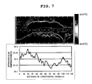
- the transducer unit and the temperature sensor are disposed in the distal end portion, or a probe, of the ultrasonic catheter for simultaneously displaying intravascular ultrasonic tomographic and longitudinal tomographic images and an intravascular temperature distribution in blood vessel and plaque regions.
- the intravascular ultrasonic tomographic and longitudinal tomographic images and the intravascular temperature distribution which are displayed are useful in finding a region where a plaque has been formed and also a region where a plaque will possibly be formed, and making subsequent medical treatment.
- the intravascular ultrasonic transverse tomographic image may be divided into differently featured, e.g., differently colored, segments based on information obtained from the temperature data, and the divided segments are displayed.
- the differently featured segments allow a volume such as a plaque to be easily determined in the tomographic image of the blood vessel.
- the intravascular ultrasonic longitudinal tomographic image may be divided into differently featured, e.g., differently colored, segments based on information obtained from the temperature data, and the divided segments are displayed.
- the differently featured segments allow a volume such as a plaque to be easily determined in the scanning direction of the image core in the blood vessel.
- the intravascular ultrasonic transverse tomographic image and the intravascular ultrasonic longitudinal tomographic image allow blood vessel diameters such as intima and middle coat diameters to be measured relatively easily.
Landscapes
- Life Sciences & Earth Sciences (AREA)
- Health & Medical Sciences (AREA)
- Surgery (AREA)
- Molecular Biology (AREA)
- Veterinary Medicine (AREA)
- Pathology (AREA)
- Public Health (AREA)
- Engineering & Computer Science (AREA)
- Biomedical Technology (AREA)
- Heart & Thoracic Surgery (AREA)
- Medical Informatics (AREA)
- Biophysics (AREA)
- Physics & Mathematics (AREA)
- Animal Behavior & Ethology (AREA)
- General Health & Medical Sciences (AREA)
- Radiology & Medical Imaging (AREA)
- Nuclear Medicine, Radiotherapy & Molecular Imaging (AREA)
- Ultra Sonic Daignosis Equipment (AREA)
- Measuring And Recording Apparatus For Diagnosis (AREA)
Applications Claiming Priority (2)
| Application Number | Priority Date | Filing Date | Title |
|---|---|---|---|
| JP2004090019 | 2004-03-25 | ||
| JP2004090019A JP4554967B2 (ja) | 2004-03-25 | 2004-03-25 | 超音波カテーテルおよび画像診断装置 |
Publications (2)
| Publication Number | Publication Date |
|---|---|
| EP1579807A1 true EP1579807A1 (de) | 2005-09-28 |
| EP1579807B1 EP1579807B1 (de) | 2010-10-20 |
Family
ID=34858475
Family Applications (1)
| Application Number | Title | Priority Date | Filing Date |
|---|---|---|---|
| EP05005958A Expired - Lifetime EP1579807B1 (de) | 2004-03-25 | 2005-03-18 | Ultraschallabbildungssystem |
Country Status (5)
| Country | Link |
|---|---|
| US (1) | US8029446B2 (de) |
| EP (1) | EP1579807B1 (de) |
| JP (1) | JP4554967B2 (de) |
| AT (1) | ATE485005T1 (de) |
| DE (1) | DE602005024203D1 (de) |
Cited By (1)
| Publication number | Priority date | Publication date | Assignee | Title |
|---|---|---|---|---|
| WO2014031854A1 (en) | 2012-08-23 | 2014-02-27 | Volcano Corporation | Device, system, and method utilizing a radiopaque element for anatomical lesion length estimation |
Families Citing this family (33)
| Publication number | Priority date | Publication date | Assignee | Title |
|---|---|---|---|---|
| DE102005044889A1 (de) * | 2005-09-20 | 2007-03-29 | Siemens Ag | Zahnmedizinisches Untersuchungs- und/oder Behandlungswerkezug |
| US20070129625A1 (en) * | 2005-11-21 | 2007-06-07 | Boston Scientific Scimed Systems, Inc. | Systems and methods for detecting the presence of abnormalities in a medical image |
| DE102005059262B4 (de) * | 2005-12-12 | 2008-02-07 | Siemens Ag | Kathetervorrichtung |
| US20090105588A1 (en) * | 2007-10-02 | 2009-04-23 | Board Of Regents, The University Of Texas System | Real-Time Ultrasound Monitoring of Heat-Induced Tissue Interactions |
| DK2268200T3 (en) * | 2008-03-18 | 2019-01-07 | Circa Scient Llc | TEMPERATURE MEASURING EQUIPMENT WITH LARGE SURFACE AREA |
| US9833149B2 (en) | 2008-03-18 | 2017-12-05 | Circa Scientific, Llc | Methods, apparatus and systems for facilitating introduction of shaped medical instruments into the body of a subject |
| US8175684B2 (en) * | 2008-07-29 | 2012-05-08 | General Electric Company | Method for processing images and associated medical imaging system |
| CA2803747C (en) | 2008-09-11 | 2016-10-25 | Acist Medical Systems, Inc. | Physiological sensor delivery device and method |
| EP2358278B1 (de) * | 2008-12-08 | 2021-05-12 | Acist Medical Systems, Inc. | System und katheter zur bildführung und verfahren dafür |
| US9744339B2 (en) | 2010-05-12 | 2017-08-29 | Circa Scientific, Llc | Apparatus for manually manipulating hollow organs |
| EP2642913B1 (de) | 2010-11-27 | 2024-02-21 | Boston Scientific Scimed, Inc. | Ablations- und temperaturmessvorrichtungen |
| EP2706908B1 (de) | 2011-05-11 | 2019-07-10 | Acist Medical Systems, Inc. | Intravaskuläres messsystem |
| EP2742329B1 (de) * | 2011-09-02 | 2017-12-27 | Koninklijke Philips N.V. | Informationen bezüglich einbringen und herausnehmen einer medizinischen vorrichtung mithilfe verteilter glasfaser-temperaturmessung |
| WO2014022556A1 (en) | 2012-08-02 | 2014-02-06 | Volcano Corporation | Method for seam elimination and reconstruction of coplanar images from intravascular ultrasonic data |
| WO2014045327A1 (ja) * | 2012-09-24 | 2014-03-27 | テルモ株式会社 | 画像診断装置及び画像処理方法 |
| CA2895769A1 (en) * | 2012-12-21 | 2014-06-26 | Douglas Meyer | Rotational ultrasound imaging catheter with extended catheter body telescope |
| US9713456B2 (en) | 2013-12-30 | 2017-07-25 | Acist Medical Systems, Inc. | Position sensing in intravascular imaging |
| US10244951B2 (en) | 2014-06-10 | 2019-04-02 | Acist Medical Systems, Inc. | Physiological sensor delivery device and method |
| CN107072501B (zh) * | 2015-04-01 | 2019-07-23 | 奥林巴斯株式会社 | 插入装置 |
| WO2016168605A1 (en) | 2015-04-16 | 2016-10-20 | Gentuity, Llc | Micro-optic probes for neurology |
| US9987089B2 (en) | 2015-07-13 | 2018-06-05 | University of Central Oklahoma | Device and a method for imaging-guided photothermal laser therapy for cancer treatment |
| EP4675259A3 (de) | 2015-08-31 | 2026-04-08 | Spryte Medical, Inc. | Bildgebungssystem mit bildgebungssonde und abgabevorrichtungen |
| JP6599702B2 (ja) * | 2015-09-10 | 2019-10-30 | テルモ株式会社 | 画像診断用カテーテル |
| JP6963567B2 (ja) | 2016-05-19 | 2021-11-10 | アシスト・メディカル・システムズ,インコーポレイテッド | 血管内プロセスにおける位置検知 |
| CN109561879B (zh) | 2016-05-19 | 2022-03-29 | 阿西斯特医疗系统有限公司 | 血管内过程中的位置感测 |
| JP7160935B2 (ja) | 2017-11-28 | 2022-10-25 | ジェンテュイティ・リミテッド・ライアビリティ・カンパニー | 撮像システム |
| EP3781026B1 (de) | 2018-04-20 | 2022-05-18 | ACIST Medical Systems, Inc. | Beurteilung eines gefässes |
| JP2022500174A (ja) | 2018-09-17 | 2022-01-04 | ジェンテュイティ・リミテッド・ライアビリティ・カンパニーGentuity, LLC | 光学経路を有する撮像システム |
| WO2020223433A1 (en) | 2019-04-30 | 2020-11-05 | Gentuity, Llc | Imaging probe with fluid pressurization element |
| US12239412B2 (en) | 2019-05-21 | 2025-03-04 | Spryte Medical, Inc. | Systems and methods for OCT-guided treatment of a patient |
| JP2020163131A (ja) * | 2020-03-18 | 2020-10-08 | パイオニア株式会社 | 呼吸音解析装置 |
| CN116831631A (zh) * | 2023-07-26 | 2023-10-03 | 深圳皓影医疗科技有限公司 | 一种血管内超声诊断导管及其伸缩组件 |
| CN120154358B (zh) * | 2025-03-17 | 2025-12-12 | 深圳开立生物医疗科技股份有限公司 | 血管探测系统、电子设备、存储介质和计算机程序产品 |
Citations (4)
| Publication number | Priority date | Publication date | Assignee | Title |
|---|---|---|---|---|
| JPH04138147A (ja) * | 1990-09-28 | 1992-05-12 | Aloka Co Ltd | 超音波探触子 |
| US5924997A (en) * | 1996-07-29 | 1999-07-20 | Campbell; Thomas Henderson | Catheter and method for the thermal mapping of hot spots in vascular lesions of the human body |
| US6290675B1 (en) * | 1997-01-09 | 2001-09-18 | Endosonics Corporation | Device for withdrawing a catheter |
| WO2003088817A2 (en) * | 2002-04-19 | 2003-10-30 | Kenneth Michlitsch J | Methods and apparatus for the identification and stabilization of vulnerable plaque |
Family Cites Families (22)
| Publication number | Priority date | Publication date | Assignee | Title |
|---|---|---|---|---|
| JPH02289238A (ja) * | 1989-03-23 | 1990-11-29 | Olympus Optical Co Ltd | 生体内情報検知装置 |
| JPH02252445A (ja) * | 1989-03-27 | 1990-10-11 | Olympus Optical Co Ltd | 生体内情報検知具 |
| GB2268614B (en) | 1992-07-06 | 1996-01-10 | Sony Broadcast & Communication | Digital signal recording |
| US5336178A (en) * | 1992-11-02 | 1994-08-09 | Localmed, Inc. | Intravascular catheter with infusion array |
| US5469852A (en) * | 1993-03-12 | 1995-11-28 | Kabushiki Kaisha Toshiba | Ultrasound diagnosis apparatus and probe therefor |
| US5596995A (en) * | 1995-05-02 | 1997-01-28 | Heart Rhythm Technologies, Inc. | Biomedical device having a temperature sensing system |
| EP0955883B1 (de) | 1995-09-20 | 2002-07-31 | Texas Heart Institute | yNZEIGE VON THERMISCHEN UNSTETIGKEITEN AN GEFÄSSWÄNDEN |
| US6615071B1 (en) | 1995-09-20 | 2003-09-02 | Board Of Regents, The University Of Texas System | Method and apparatus for detecting vulnerable atherosclerotic plaque |
| US6763261B2 (en) | 1995-09-20 | 2004-07-13 | Board Of Regents, The University Of Texas System | Method and apparatus for detecting vulnerable atherosclerotic plaque |
| US6245026B1 (en) * | 1996-07-29 | 2001-06-12 | Farallon Medsystems, Inc. | Thermography catheter |
| JP2000229083A (ja) * | 1999-01-07 | 2000-08-22 | Terumo Corp | 超音波カテーテル |
| JP2002136537A (ja) * | 2000-11-01 | 2002-05-14 | Aloka Co Ltd | 血管治療装置及び血管診断治療システム |
| US6514214B2 (en) * | 2001-02-13 | 2003-02-04 | Scimed Life Systems, Inc. | Intravascular temperature sensor |
| US20020115931A1 (en) * | 2001-02-21 | 2002-08-22 | Strauss H. William | Localizing intravascular lesions on anatomic images |
| US20030013986A1 (en) * | 2001-07-12 | 2003-01-16 | Vahid Saadat | Device for sensing temperature profile of a hollow body organ |
| JP3701248B2 (ja) * | 2002-02-22 | 2005-09-28 | 西松建設株式会社 | コンクリート製床版部の検査方法 |
| US20030199747A1 (en) * | 2002-04-19 | 2003-10-23 | Michlitsch Kenneth J. | Methods and apparatus for the identification and stabilization of vulnerable plaque |
| US20030199767A1 (en) * | 2002-04-19 | 2003-10-23 | Cespedes Eduardo Ignacio | Methods and apparatus for the identification and stabilization of vulnerable plaque |
| JP2004085391A (ja) * | 2002-08-27 | 2004-03-18 | Fujitsu Ltd | 温度計測システム及び温度計測方法 |
| JP2005066142A (ja) * | 2003-08-27 | 2005-03-17 | Aloka Co Ltd | カテーテル型超音波探触子 |
| US6949072B2 (en) * | 2003-09-22 | 2005-09-27 | Infraredx, Inc. | Devices for vulnerable plaque detection |
| US20060173318A1 (en) * | 2004-07-20 | 2006-08-03 | Scimed Life Systems Inc. | Systems and methods for detecting and presenting textural information from medical images |
-
2004
- 2004-03-25 JP JP2004090019A patent/JP4554967B2/ja not_active Expired - Fee Related
-
2005
- 2005-03-18 DE DE602005024203T patent/DE602005024203D1/de not_active Expired - Lifetime
- 2005-03-18 EP EP05005958A patent/EP1579807B1/de not_active Expired - Lifetime
- 2005-03-18 AT AT05005958T patent/ATE485005T1/de not_active IP Right Cessation
- 2005-03-25 US US11/089,330 patent/US8029446B2/en active Active
Patent Citations (4)
| Publication number | Priority date | Publication date | Assignee | Title |
|---|---|---|---|---|
| JPH04138147A (ja) * | 1990-09-28 | 1992-05-12 | Aloka Co Ltd | 超音波探触子 |
| US5924997A (en) * | 1996-07-29 | 1999-07-20 | Campbell; Thomas Henderson | Catheter and method for the thermal mapping of hot spots in vascular lesions of the human body |
| US6290675B1 (en) * | 1997-01-09 | 2001-09-18 | Endosonics Corporation | Device for withdrawing a catheter |
| WO2003088817A2 (en) * | 2002-04-19 | 2003-10-30 | Kenneth Michlitsch J | Methods and apparatus for the identification and stabilization of vulnerable plaque |
Non-Patent Citations (1)
| Title |
|---|
| PATENT ABSTRACTS OF JAPAN vol. 016, no. 411 (C - 0979) 31 August 1992 (1992-08-31) * |
Cited By (6)
| Publication number | Priority date | Publication date | Assignee | Title |
|---|---|---|---|---|
| WO2014031854A1 (en) | 2012-08-23 | 2014-02-27 | Volcano Corporation | Device, system, and method utilizing a radiopaque element for anatomical lesion length estimation |
| US10561473B2 (en) | 2012-08-23 | 2020-02-18 | Philips Image Guided Therapy Corporation | Device, system, and method utilizing a radiopaque element for anatomical lesion length estimation |
| EP2887993B1 (de) * | 2012-08-23 | 2020-10-07 | Volcano Corporation | Vorrichtung mit einem röntgendichten element zur schätzung der länge von anatomischen läsionen |
| US11850102B2 (en) | 2012-08-23 | 2023-12-26 | Philips Image Guided Therapy Corporation | Device, system, and method utilizing a radiopaque element for anatomical lesion length estimation |
| US11950965B2 (en) | 2012-08-23 | 2024-04-09 | Philips Image Guided Therapy Corporation | Device, system, and method utilizing a radiopaque element for anatomical lesion length estimation |
| US12402971B2 (en) | 2012-08-23 | 2025-09-02 | Philips Image Guided Therapy Corporation | Device, system, and method utilizing a radiopaque element for anatomical lesion length estimation |
Also Published As
| Publication number | Publication date |
|---|---|
| EP1579807B1 (de) | 2010-10-20 |
| ATE485005T1 (de) | 2010-11-15 |
| US20060241484A1 (en) | 2006-10-26 |
| US8029446B2 (en) | 2011-10-04 |
| JP4554967B2 (ja) | 2010-09-29 |
| DE602005024203D1 (de) | 2010-12-02 |
| JP2005270425A (ja) | 2005-10-06 |
Similar Documents
| Publication | Publication Date | Title |
|---|---|---|
| EP1579807B1 (de) | Ultraschallabbildungssystem | |
| USRE50513E1 (en) | Systems and methods for improved visualization during minimally invasive procedures | |
| US10905394B2 (en) | Dual lumen diagnostic catheter | |
| JP4675613B2 (ja) | 医療検査および/または治療システム | |
| US8052605B2 (en) | Multimodal catheter system and method for intravascular analysis | |
| EP2559374B1 (de) | System und Vorrichtung zur Bilddiagnose | |
| US20030199768A1 (en) | Methods and apparatus for the identification and stabilization of vulnerable plaque | |
| US20030199767A1 (en) | Methods and apparatus for the identification and stabilization of vulnerable plaque | |
| US6175757B1 (en) | Luminal mapping | |
| US20030032880A1 (en) | Apparatus and method for ultrasonically identifying vulnerable plaque | |
| CN113180631A (zh) | 基于血管内成像的血流速度、血流储备分数的分析方法 | |
| EP3117775B1 (de) | Steuerungsvorrichtung sowie diagnosesystem dafür | |
| EP2832287B1 (de) | Bilddiagnosevorrichtung und sonde | |
| JP2005095624A (ja) | 医療検査および/または治療システム | |
| CN111462117B (zh) | 基于血管图像的数据处理系统及其数据处理方法 | |
| EP3378406B1 (de) | Abbildungsvorrichtung zur diagnose und betriebsverfahren und programm dafür | |
| JPH0417843A (ja) | 超音波診断装置 | |
| CN212365043U (zh) | 基于血管图像的数据处理系统 | |
| Pandian et al. | Intravascular ultrasound estimation of arterial stenosis | |
| CN120189605A (zh) | 一种诊断导管和数据收集系统的控制方法 | |
| US20220133134A1 (en) | Imaging and pressure sensing apparatus and probes with a slidable sheath | |
| CN120154358A (zh) | 血管探测系统、电子设备、存储介质和计算机程序产品 |
Legal Events
| Date | Code | Title | Description |
|---|---|---|---|
| PUAI | Public reference made under article 153(3) epc to a published international application that has entered the european phase |
Free format text: ORIGINAL CODE: 0009012 |
|
| AK | Designated contracting states |
Kind code of ref document: A1 Designated state(s): AT BE BG CH CY CZ DE DK EE ES FI FR GB GR HU IE IS IT LI LT LU MC NL PL PT RO SE SI SK TR |
|
| AX | Request for extension of the european patent |
Extension state: AL BA HR LV MK YU |
|
| 17P | Request for examination filed |
Effective date: 20060203 |
|
| AKX | Designation fees paid |
Designated state(s): AT BE BG CH CY CZ DE DK EE ES FI FR GB GR HU IE IS IT LI LT LU MC NL PL PT RO SE SI SK TR |
|
| 17Q | First examination report despatched |
Effective date: 20081215 |
|
| GRAP | Despatch of communication of intention to grant a patent |
Free format text: ORIGINAL CODE: EPIDOSNIGR1 |
|
| GRAS | Grant fee paid |
Free format text: ORIGINAL CODE: EPIDOSNIGR3 |
|
| GRAA | (expected) grant |
Free format text: ORIGINAL CODE: 0009210 |
|
| AK | Designated contracting states |
Kind code of ref document: B1 Designated state(s): AT BE BG CH CY CZ DE DK EE ES FI FR GB GR HU IE IS IT LI LT LU MC NL PL PT RO SE SI SK TR |
|
| REG | Reference to a national code |
Ref country code: GB Ref legal event code: FG4D |
|
| REG | Reference to a national code |
Ref country code: CH Ref legal event code: EP |
|
| REG | Reference to a national code |
Ref country code: IE Ref legal event code: FG4D |
|
| REF | Corresponds to: |
Ref document number: 602005024203 Country of ref document: DE Date of ref document: 20101202 Kind code of ref document: P |
|
| REG | Reference to a national code |
Ref country code: NL Ref legal event code: VDEP Effective date: 20101020 |
|
| LTIE | Lt: invalidation of european patent or patent extension |
Effective date: 20101020 |
|
| PG25 | Lapsed in a contracting state [announced via postgrant information from national office to epo] |
Ref country code: LT Free format text: LAPSE BECAUSE OF FAILURE TO SUBMIT A TRANSLATION OF THE DESCRIPTION OR TO PAY THE FEE WITHIN THE PRESCRIBED TIME-LIMIT Effective date: 20101020 |
|
| PG25 | Lapsed in a contracting state [announced via postgrant information from national office to epo] |
Ref country code: SI Free format text: LAPSE BECAUSE OF FAILURE TO SUBMIT A TRANSLATION OF THE DESCRIPTION OR TO PAY THE FEE WITHIN THE PRESCRIBED TIME-LIMIT Effective date: 20101020 Ref country code: BG Free format text: LAPSE BECAUSE OF FAILURE TO SUBMIT A TRANSLATION OF THE DESCRIPTION OR TO PAY THE FEE WITHIN THE PRESCRIBED TIME-LIMIT Effective date: 20110120 Ref country code: IS Free format text: LAPSE BECAUSE OF FAILURE TO SUBMIT A TRANSLATION OF THE DESCRIPTION OR TO PAY THE FEE WITHIN THE PRESCRIBED TIME-LIMIT Effective date: 20110220 Ref country code: NL Free format text: LAPSE BECAUSE OF FAILURE TO SUBMIT A TRANSLATION OF THE DESCRIPTION OR TO PAY THE FEE WITHIN THE PRESCRIBED TIME-LIMIT Effective date: 20101020 Ref country code: AT Free format text: LAPSE BECAUSE OF FAILURE TO SUBMIT A TRANSLATION OF THE DESCRIPTION OR TO PAY THE FEE WITHIN THE PRESCRIBED TIME-LIMIT Effective date: 20101020 Ref country code: FI Free format text: LAPSE BECAUSE OF FAILURE TO SUBMIT A TRANSLATION OF THE DESCRIPTION OR TO PAY THE FEE WITHIN THE PRESCRIBED TIME-LIMIT Effective date: 20101020 Ref country code: PT Free format text: LAPSE BECAUSE OF FAILURE TO SUBMIT A TRANSLATION OF THE DESCRIPTION OR TO PAY THE FEE WITHIN THE PRESCRIBED TIME-LIMIT Effective date: 20110221 Ref country code: SE Free format text: LAPSE BECAUSE OF FAILURE TO SUBMIT A TRANSLATION OF THE DESCRIPTION OR TO PAY THE FEE WITHIN THE PRESCRIBED TIME-LIMIT Effective date: 20101020 |
|
| PG25 | Lapsed in a contracting state [announced via postgrant information from national office to epo] |
Ref country code: BE Free format text: LAPSE BECAUSE OF FAILURE TO SUBMIT A TRANSLATION OF THE DESCRIPTION OR TO PAY THE FEE WITHIN THE PRESCRIBED TIME-LIMIT Effective date: 20101020 Ref country code: GR Free format text: LAPSE BECAUSE OF FAILURE TO SUBMIT A TRANSLATION OF THE DESCRIPTION OR TO PAY THE FEE WITHIN THE PRESCRIBED TIME-LIMIT Effective date: 20110121 |
|
| PG25 | Lapsed in a contracting state [announced via postgrant information from national office to epo] |
Ref country code: EE Free format text: LAPSE BECAUSE OF FAILURE TO SUBMIT A TRANSLATION OF THE DESCRIPTION OR TO PAY THE FEE WITHIN THE PRESCRIBED TIME-LIMIT Effective date: 20101020 Ref country code: ES Free format text: LAPSE BECAUSE OF FAILURE TO SUBMIT A TRANSLATION OF THE DESCRIPTION OR TO PAY THE FEE WITHIN THE PRESCRIBED TIME-LIMIT Effective date: 20110131 Ref country code: CZ Free format text: LAPSE BECAUSE OF FAILURE TO SUBMIT A TRANSLATION OF THE DESCRIPTION OR TO PAY THE FEE WITHIN THE PRESCRIBED TIME-LIMIT Effective date: 20101020 |
|
| PLBE | No opposition filed within time limit |
Free format text: ORIGINAL CODE: 0009261 |
|
| STAA | Information on the status of an ep patent application or granted ep patent |
Free format text: STATUS: NO OPPOSITION FILED WITHIN TIME LIMIT |
|
| PG25 | Lapsed in a contracting state [announced via postgrant information from national office to epo] |
Ref country code: PL Free format text: LAPSE BECAUSE OF FAILURE TO SUBMIT A TRANSLATION OF THE DESCRIPTION OR TO PAY THE FEE WITHIN THE PRESCRIBED TIME-LIMIT Effective date: 20101020 Ref country code: SK Free format text: LAPSE BECAUSE OF FAILURE TO SUBMIT A TRANSLATION OF THE DESCRIPTION OR TO PAY THE FEE WITHIN THE PRESCRIBED TIME-LIMIT Effective date: 20101020 Ref country code: DK Free format text: LAPSE BECAUSE OF FAILURE TO SUBMIT A TRANSLATION OF THE DESCRIPTION OR TO PAY THE FEE WITHIN THE PRESCRIBED TIME-LIMIT Effective date: 20101020 Ref country code: RO Free format text: LAPSE BECAUSE OF FAILURE TO SUBMIT A TRANSLATION OF THE DESCRIPTION OR TO PAY THE FEE WITHIN THE PRESCRIBED TIME-LIMIT Effective date: 20101020 |
|
| 26N | No opposition filed |
Effective date: 20110721 |
|
| PG25 | Lapsed in a contracting state [announced via postgrant information from national office to epo] |
Ref country code: MC Free format text: LAPSE BECAUSE OF NON-PAYMENT OF DUE FEES Effective date: 20110331 |
|
| REG | Reference to a national code |
Ref country code: CH Ref legal event code: PL |
|
| REG | Reference to a national code |
Ref country code: DE Ref legal event code: R097 Ref document number: 602005024203 Country of ref document: DE Effective date: 20110721 |
|
| PG25 | Lapsed in a contracting state [announced via postgrant information from national office to epo] |
Ref country code: IT Free format text: LAPSE BECAUSE OF FAILURE TO SUBMIT A TRANSLATION OF THE DESCRIPTION OR TO PAY THE FEE WITHIN THE PRESCRIBED TIME-LIMIT Effective date: 20101020 |
|
| REG | Reference to a national code |
Ref country code: IE Ref legal event code: MM4A |
|
| PG25 | Lapsed in a contracting state [announced via postgrant information from national office to epo] |
Ref country code: LI Free format text: LAPSE BECAUSE OF NON-PAYMENT OF DUE FEES Effective date: 20110331 Ref country code: IE Free format text: LAPSE BECAUSE OF NON-PAYMENT OF DUE FEES Effective date: 20110318 Ref country code: CH Free format text: LAPSE BECAUSE OF NON-PAYMENT OF DUE FEES Effective date: 20110331 |
|
| PG25 | Lapsed in a contracting state [announced via postgrant information from national office to epo] |
Ref country code: LU Free format text: LAPSE BECAUSE OF NON-PAYMENT OF DUE FEES Effective date: 20110318 Ref country code: CY Free format text: LAPSE BECAUSE OF FAILURE TO SUBMIT A TRANSLATION OF THE DESCRIPTION OR TO PAY THE FEE WITHIN THE PRESCRIBED TIME-LIMIT Effective date: 20101020 |
|
| PG25 | Lapsed in a contracting state [announced via postgrant information from national office to epo] |
Ref country code: TR Free format text: LAPSE BECAUSE OF FAILURE TO SUBMIT A TRANSLATION OF THE DESCRIPTION OR TO PAY THE FEE WITHIN THE PRESCRIBED TIME-LIMIT Effective date: 20101020 |
|
| PG25 | Lapsed in a contracting state [announced via postgrant information from national office to epo] |
Ref country code: HU Free format text: LAPSE BECAUSE OF FAILURE TO SUBMIT A TRANSLATION OF THE DESCRIPTION OR TO PAY THE FEE WITHIN THE PRESCRIBED TIME-LIMIT Effective date: 20101020 |
|
| REG | Reference to a national code |
Ref country code: FR Ref legal event code: PLFP Year of fee payment: 12 |
|
| REG | Reference to a national code |
Ref country code: FR Ref legal event code: PLFP Year of fee payment: 13 |
|
| REG | Reference to a national code |
Ref country code: FR Ref legal event code: PLFP Year of fee payment: 14 |
|
| PGFP | Annual fee paid to national office [announced via postgrant information from national office to epo] |
Ref country code: FR Payment date: 20230208 Year of fee payment: 19 |
|
| PGFP | Annual fee paid to national office [announced via postgrant information from national office to epo] |
Ref country code: GB Payment date: 20230202 Year of fee payment: 19 Ref country code: DE Payment date: 20230131 Year of fee payment: 19 |
|
| REG | Reference to a national code |
Ref country code: DE Ref legal event code: R119 Ref document number: 602005024203 Country of ref document: DE |
|
| GBPC | Gb: european patent ceased through non-payment of renewal fee |
Effective date: 20240318 |
|
| PG25 | Lapsed in a contracting state [announced via postgrant information from national office to epo] |
Ref country code: DE Free format text: LAPSE BECAUSE OF NON-PAYMENT OF DUE FEES Effective date: 20241001 |
|
| PG25 | Lapsed in a contracting state [announced via postgrant information from national office to epo] |
Ref country code: GB Free format text: LAPSE BECAUSE OF NON-PAYMENT OF DUE FEES Effective date: 20240318 |
|
| PG25 | Lapsed in a contracting state [announced via postgrant information from national office to epo] |
Ref country code: FR Free format text: LAPSE BECAUSE OF NON-PAYMENT OF DUE FEES Effective date: 20240331 |
|
| PG25 | Lapsed in a contracting state [announced via postgrant information from national office to epo] |
Ref country code: GB Free format text: LAPSE BECAUSE OF NON-PAYMENT OF DUE FEES Effective date: 20240318 Ref country code: FR Free format text: LAPSE BECAUSE OF NON-PAYMENT OF DUE FEES Effective date: 20240331 Ref country code: DE Free format text: LAPSE BECAUSE OF NON-PAYMENT OF DUE FEES Effective date: 20241001 |