EP1579742B1 - Wechselrichter zum speisen zweier gasentladungslampen - Google Patents
Wechselrichter zum speisen zweier gasentladungslampen Download PDFInfo
- Publication number
- EP1579742B1 EP1579742B1 EP03775717A EP03775717A EP1579742B1 EP 1579742 B1 EP1579742 B1 EP 1579742B1 EP 03775717 A EP03775717 A EP 03775717A EP 03775717 A EP03775717 A EP 03775717A EP 1579742 B1 EP1579742 B1 EP 1579742B1
- Authority
- EP
- European Patent Office
- Prior art keywords
- control
- converter
- lamps
- switch elements
- junction
- Prior art date
- Legal status (The legal status is an assumption and is not a legal conclusion. Google has not performed a legal analysis and makes no representation as to the accuracy of the status listed.)
- Expired - Lifetime
Links
- 239000003990 capacitor Substances 0.000 claims description 10
- 239000004065 semiconductor Substances 0.000 description 4
- 230000006378 damage Effects 0.000 description 2
- 238000000034 method Methods 0.000 description 2
- 230000000087 stabilizing effect Effects 0.000 description 2
- 238000006243 chemical reaction Methods 0.000 description 1
- 238000010276 construction Methods 0.000 description 1
- 238000010586 diagram Methods 0.000 description 1
- 230000004907 flux Effects 0.000 description 1
- 230000002452 interceptive effect Effects 0.000 description 1
Images
Classifications
-
- H—ELECTRICITY
- H05—ELECTRIC TECHNIQUES NOT OTHERWISE PROVIDED FOR
- H05B—ELECTRIC HEATING; ELECTRIC LIGHT SOURCES NOT OTHERWISE PROVIDED FOR; CIRCUIT ARRANGEMENTS FOR ELECTRIC LIGHT SOURCES, IN GENERAL
- H05B41/00—Circuit arrangements or apparatus for igniting or operating discharge lamps
- H05B41/14—Circuit arrangements
- H05B41/36—Controlling
- H05B41/38—Controlling the intensity of light
- H05B41/39—Controlling the intensity of light continuously
- H05B41/392—Controlling the intensity of light continuously using semiconductor devices, e.g. thyristor
- H05B41/3921—Controlling the intensity of light continuously using semiconductor devices, e.g. thyristor with possibility of light intensity variations
- H05B41/3927—Controlling the intensity of light continuously using semiconductor devices, e.g. thyristor with possibility of light intensity variations by pulse width modulation
- H05B41/3928—Controlling the intensity of light continuously using semiconductor devices, e.g. thyristor with possibility of light intensity variations by pulse width modulation for high-pressure lamps, e.g. high-intensity discharge lamps, high-pressure mercury or sodium lamps
-
- H—ELECTRICITY
- H05—ELECTRIC TECHNIQUES NOT OTHERWISE PROVIDED FOR
- H05B—ELECTRIC HEATING; ELECTRIC LIGHT SOURCES NOT OTHERWISE PROVIDED FOR; CIRCUIT ARRANGEMENTS FOR ELECTRIC LIGHT SOURCES, IN GENERAL
- H05B41/00—Circuit arrangements or apparatus for igniting or operating discharge lamps
- H05B41/14—Circuit arrangements
- H05B41/26—Circuit arrangements in which the lamp is fed by power derived from DC by means of a converter, e.g. by high-voltage DC
- H05B41/28—Circuit arrangements in which the lamp is fed by power derived from DC by means of a converter, e.g. by high-voltage DC using static converters
- H05B41/288—Circuit arrangements in which the lamp is fed by power derived from DC by means of a converter, e.g. by high-voltage DC using static converters with semiconductor devices and specially adapted for lamps without preheating electrodes, e.g. for high-intensity discharge lamps, high-pressure mercury or sodium lamps or low-pressure sodium lamps
- H05B41/2885—Static converters especially adapted therefor; Control thereof
- H05B41/2887—Static converters especially adapted therefor; Control thereof characterised by a controllable bridge in the final stage
- H05B41/2888—Static converters especially adapted therefor; Control thereof characterised by a controllable bridge in the final stage the bridge being commutated at low frequency, e.g. 1kHz
-
- Y—GENERAL TAGGING OF NEW TECHNOLOGICAL DEVELOPMENTS; GENERAL TAGGING OF CROSS-SECTIONAL TECHNOLOGIES SPANNING OVER SEVERAL SECTIONS OF THE IPC; TECHNICAL SUBJECTS COVERED BY FORMER USPC CROSS-REFERENCE ART COLLECTIONS [XRACs] AND DIGESTS
- Y02—TECHNOLOGIES OR APPLICATIONS FOR MITIGATION OR ADAPTATION AGAINST CLIMATE CHANGE
- Y02B—CLIMATE CHANGE MITIGATION TECHNOLOGIES RELATED TO BUILDINGS, e.g. HOUSING, HOUSE APPLIANCES OR RELATED END-USER APPLICATIONS
- Y02B20/00—Energy efficient lighting technologies, e.g. halogen lamps or gas discharge lamps
-
- Y—GENERAL TAGGING OF NEW TECHNOLOGICAL DEVELOPMENTS; GENERAL TAGGING OF CROSS-SECTIONAL TECHNOLOGIES SPANNING OVER SEVERAL SECTIONS OF THE IPC; TECHNICAL SUBJECTS COVERED BY FORMER USPC CROSS-REFERENCE ART COLLECTIONS [XRACs] AND DIGESTS
- Y10—TECHNICAL SUBJECTS COVERED BY FORMER USPC
- Y10S—TECHNICAL SUBJECTS COVERED BY FORMER USPC CROSS-REFERENCE ART COLLECTIONS [XRACs] AND DIGESTS
- Y10S315/00—Electric lamp and discharge devices: systems
- Y10S315/07—Starting and control circuits for gas discharge lamp using transistors
Definitions
- the invention relates to a DC/AC converter for supplying two gas discharge lamps, comprising a pair of input terminals for supplying a DC voltage, a first series circuit interconnecting the input terminals, comprising a first switching element and a second switching element, a second series circuit interconnecting the input terminals, comprising a third switching element and a fourth switching element, a third series circuit interconnecting the input terminals, comprising a first capacitor and a second capacitor with substantially equal capacitance, a first gas discharge lamp connected between the junction between the first and the second switch element and the junction between the two capacitors, a second gas discharge lamp connected between the junction between the third and the fourth switch element and the junction between the two capacitors, wherein an inductor is connected in series with each of the lamps and a control circuit for controlling the first to fourth switch elements, and which is adapted to avoid the simultaneously conducting of the first and second switch elements the third and the fourth switch elements respectively.
- Such a DC/AC converter is disclosed in EP-A-0 395 159 .
- the aim of the invention is to provide such a DC/AC converter of the kind mentioned above of which the power supplied to the lamps can be controlled.
- control element is adapted to control the conducting periods of the switches with a duty cycle which is variable.
- control of the power supplied to the lamps is important, in particular for the starting of the lamp.
- control of the conducting periods of the switch elements a proper control of the energy supplied to the lamps is obtained.
- control unit is adapted to control the duty cycle of the first and second switch elements simultaneously and to control the duty cycle of the third and fourth switch elements simultaneously.
- This facility offers the possibility of independent control of the power supplied to each of the lamps. This is not only important for control of the light output of the lamps, but also for the starting procedure. It is conceivable that both lamps present in the circuit have more or less different properties, so that ignition of one lamp may take place earlier than ignition of the other lamp.
- the independent control of the power supplied to each of the lamps the 'take over' from the ignition to the steady state is adaptable to the processes taking place in each of the lamps.
- control unit is adapted to control the switches with a frequency in the band between 140Hz and 170Hz.
- a series circuit of an inductor and a diode is connected between the input terminal and the first switching element, wherein a fifth switching element is connected between the junction of the diode and the inductor and the second input terminal and the fifth switch element is controlled by the control circuit.
- This circuit provides an extra control for the voltage to be supplied to the double bridge circuit.
- This extra control function may be used for keeping the voltage supplied to the double bridge as constant as possible, for instance in the case of a varying supply voltage.
- a last preferred embodiment teaches the feature that the frequency of the switching of the fifth switch element is at least an order of magnitude higher than that of the frequency of the first to fourth switching elements. This avoids mutual interference of both power conversion systems.
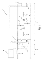
- the converter 1 comprises a double bridge circuit 2 with four switch elements 3, 4, 5, 6, which may be formed by FETs, GTOs or other controllable semiconductor switch elements.
- the junctions between the switch elements 3, 4 and 5, 6 respectively are connected to a pair of HID lamps 7, 8 connected in series.
- the double bridge circuit comprises a first input 9 connected to the positive power supply and a second input 10 connected to ground.
- a first capacitor 11 is connected between the first input 9 and the junction between the HID lamps 7, 8 and a second capacitor 12 is connected between the second input 10 and the junction between the HID lamps 7,8.
- an inductor 13, 14 In series with each of the lamps 7,8 an inductor 13, 14 respectively is connected.
- Each of the switch elements 3, 4, 5, 6 is controlled by a control circuit 15.
- the circuit as described so far functions as is described in the above referenced EP-A-0 395 159 .
- the present circuit is especially adapted to supply HID lamps which are prone to acoustical resonance, and which may lead to destruction of the lamps.
- the control circuit is adapted to control the switch elements with a frequency wherein acoustic resonance does not take place. This implies that frequencies between 500 Hz and 1000 Hz, are avoided as it is in those frequency bands that HID lamps of common types are most prone to acoustical resonance. Of course it is possible to use higher frequencies, for instance above 1000 Hz, the more as this would lead to smaller sizes of the components, but this may lead to unwanted emitting of signals interfering with communication systems operating in those frequency bands.
- the voltage of power supply may be subjected to fluctuations, which, without further measures, may lead to fluctuations of the light flux emitted by the HID lamps 7,8.
- the converter according to the present invention provides a voltage stabilizing circuit 16, which is connected between the power supply connection and the inputs of the double bridge circuit.
- the voltage stabilizing circuit comprises an inductor 17 and a diode 18 connected in series between the power supply connection and the input of the double bridge circuit.
- a fifth switch element 19 is connected between the junction between the inductor 17 and the diode 18 and ground.
- the fifth switch element 19 is also controlled by the control circuit 15. Just as the first to second switch elements 3-6, the fifth switch element 19 is be formed by a controlled semiconductor.
- the voltage level at the input of the double bridge circuit can be stabilized.
- the semiconductor switch elements will be provided with a by pass diode to avoid undue voltage stress on the junction of the semiconductor switch element, if the construction of such switch element makes this appropriate.
Landscapes
- Circuit Arrangements For Discharge Lamps (AREA)
- Pens And Brushes (AREA)
Claims (5)
- Wechselrichter zum Speisen von zwei Gasentladungslampen, mit:- einem Paar Eingangsklemmen zum Zuführen einer Gleichspannung;- einer die Eingangsklemmen miteinander verbindenden, ersten Reihenschaltung, die ein erstes Schaltelement (3) und ein zweites Schaltelement (4) aufweist;- einer die Eingangsklemmen miteinander verbindenden, zweiten Reihenschaltung, die ein drittes Schaltelement (5) und ein viertes Schaltelement (6) aufweist;- einer die Eingangsklemmen miteinander verbindenden, dritten Reihenschaltung, die einen ersten Kondensator (11) und einen zweiten Kondensator (12) mit im Wesentlichen gleicher Kapazität aufweist;- einer ersten Gasentladungslampe (7), die zwischen dem Übergang zwischen dem ersten und dem zweiten Schaltelement und dem Übergang zwischen den beiden Kondensatoren geschaltet ist;- einer zweiten Gasentladungslampe (8), die zwischen dem Übergang zwischen dem dritten und dem vierten Schaltelement und dem Übergang zwischen den beiden Kondensatoren geschaltet ist;
wobei ein Induktor (13, 14) in Reihe mit jeder der Lampen geschaltet ist; sowie- einem Steuerkreis (15), um das erste bis vierte Schaltelement zu steuern, wobei der Steuerkreis so eingerichtet ist, dass er das gleichzeitige Leiten des ersten und des zweiten Schaltelements bzw. des dritten und des vierten Schaltelements verhindert, dadurch gekennzeichnet, dass das Steuerelement so eingerichtet ist, dass es die Leitdauer der Schalter mit einem Tastverhältnis steuert, das variabel ist. - Wechselrichter nach Anspruch 1, dadurch gekennzeichnet, dass die Steuereinheit so eingerichtet ist, dass sie das Tastverhältnis des ersten und zweiten Schaltelements gleichzeitig steuert und das Tastverhältnis des dritten und vierten Schaltelements gleichzeitig steuert.
- Wechselrichter nach Anspruch 1 oder 2, dadurch gekennzeichnet, dass die Steuereinheit so eingerichtet ist, dass sie die Schaltelemente mit einer Frequenz in dem Band zwischen 140 Hz und 170 Hz steuert.
- Wechselrichter nach Anspruch 1, 2 oder 3, dadurch gekennzeichnet, dass zwischen der Eingangsklemme und dem ersten Schaltelement (3) eine Reihenschaltung aus einer Induktivität (17) und einer Diode (18) geschaltet ist, wobei ein fünftes Schaltelement (19) zwischen dem Übergang der Diode und dem Induktor und der zweiten Eingangsklemme (10) geschaltet ist und das fünfte Schaltelement von dem Steuerkreis (15) gesteuert wird.
- Wechselrichter nach Anspruch 4, dadurch gekennzeichnet, dass die Frequenz der Schaltung des fünften Schaltelements um mindestens eine Größenordnung höher als die Frequenz des ersten bis vierten Schaltelements ist.
Priority Applications (1)
| Application Number | Priority Date | Filing Date | Title |
|---|---|---|---|
| EP03775717A EP1579742B1 (de) | 2002-12-20 | 2003-12-02 | Wechselrichter zum speisen zweier gasentladungslampen |
Applications Claiming Priority (4)
| Application Number | Priority Date | Filing Date | Title |
|---|---|---|---|
| EP02080505 | 2002-12-20 | ||
| EP02080505 | 2002-12-20 | ||
| EP03775717A EP1579742B1 (de) | 2002-12-20 | 2003-12-02 | Wechselrichter zum speisen zweier gasentladungslampen |
| PCT/IB2003/005762 WO2004057933A1 (en) | 2002-12-20 | 2003-12-02 | Dc/ac converter for supplying two gas discharge lamps |
Publications (2)
| Publication Number | Publication Date |
|---|---|
| EP1579742A1 EP1579742A1 (de) | 2005-09-28 |
| EP1579742B1 true EP1579742B1 (de) | 2011-05-04 |
Family
ID=32668804
Family Applications (1)
| Application Number | Title | Priority Date | Filing Date |
|---|---|---|---|
| EP03775717A Expired - Lifetime EP1579742B1 (de) | 2002-12-20 | 2003-12-02 | Wechselrichter zum speisen zweier gasentladungslampen |
Country Status (8)
| Country | Link |
|---|---|
| US (1) | US7339326B2 (de) |
| EP (1) | EP1579742B1 (de) |
| JP (1) | JP4733985B2 (de) |
| CN (1) | CN1729729B (de) |
| AT (1) | ATE508616T1 (de) |
| AU (1) | AU2003283736A1 (de) |
| DE (1) | DE60337029D1 (de) |
| WO (1) | WO2004057933A1 (de) |
Families Citing this family (1)
| Publication number | Priority date | Publication date | Assignee | Title |
|---|---|---|---|---|
| DE102007054806A1 (de) * | 2007-11-16 | 2009-05-20 | Tridonicatco Schweiz Ag | Betriebsschaltung für in Serie geschaltete Leuchtmittel, insbesondere HID-Gasentladungslampen |
Family Cites Families (9)
| Publication number | Priority date | Publication date | Assignee | Title |
|---|---|---|---|---|
| US4734624A (en) * | 1985-07-25 | 1988-03-29 | Matsushita Electric Works, Ltd. | Discharge lamp driving circuit |
| JP2781567B2 (ja) * | 1988-09-14 | 1998-07-30 | 松下電工株式会社 | 放電灯点灯装置 |
| EP0395159B1 (de) * | 1989-04-28 | 1995-03-22 | Koninklijke Philips Electronics N.V. | Wechselrichter zum Speisen zweier Gas und / oder Dampfentladungslampen |
| IT1259553B (it) * | 1992-04-23 | 1996-03-20 | Marelli Autronica | Circuito di comando per una lampada a scarica di gas, particolarmente per l'impiego a bordo di autoveicoli |
| JPH0878171A (ja) * | 1994-08-31 | 1996-03-22 | Matsushita Electric Works Ltd | 放電灯点灯装置 |
| DE19515511A1 (de) * | 1995-04-27 | 1996-10-31 | Patent Treuhand Ges Fuer Elektrische Gluehlampen Mbh | Verfahren und Schaltungsanordnung zum Starten und Betreiben einer Entladungslampe |
| US5875103A (en) * | 1995-12-22 | 1999-02-23 | Electronic Measurements, Inc. | Full range soft-switching DC-DC converter |
| US6278245B1 (en) * | 2000-03-30 | 2001-08-21 | Philips Electronics North America Corporation | Buck-boost function type electronic ballast with bus capacitor current sensing |
| US6593703B2 (en) * | 2001-06-15 | 2003-07-15 | Matsushita Electric Works, Ltd. | Apparatus and method for driving a high intensity discharge lamp |
-
2003
- 2003-12-02 JP JP2004561808A patent/JP4733985B2/ja not_active Expired - Fee Related
- 2003-12-02 AU AU2003283736A patent/AU2003283736A1/en not_active Abandoned
- 2003-12-02 EP EP03775717A patent/EP1579742B1/de not_active Expired - Lifetime
- 2003-12-02 US US10/539,382 patent/US7339326B2/en not_active Expired - Fee Related
- 2003-12-02 WO PCT/IB2003/005762 patent/WO2004057933A1/en not_active Ceased
- 2003-12-02 AT AT03775717T patent/ATE508616T1/de not_active IP Right Cessation
- 2003-12-02 CN CN2003801068622A patent/CN1729729B/zh not_active Expired - Fee Related
- 2003-12-02 DE DE60337029T patent/DE60337029D1/de not_active Expired - Lifetime
Also Published As
| Publication number | Publication date |
|---|---|
| JP2006511051A (ja) | 2006-03-30 |
| CN1729729A (zh) | 2006-02-01 |
| US7339326B2 (en) | 2008-03-04 |
| ATE508616T1 (de) | 2011-05-15 |
| DE60337029D1 (en) | 2011-06-16 |
| EP1579742A1 (de) | 2005-09-28 |
| WO2004057933A1 (en) | 2004-07-08 |
| US20070007901A1 (en) | 2007-01-11 |
| CN1729729B (zh) | 2011-08-03 |
| AU2003283736A1 (en) | 2004-07-14 |
| JP4733985B2 (ja) | 2011-07-27 |
Similar Documents
| Publication | Publication Date | Title |
|---|---|---|
| US5426350A (en) | High frequency transformerless electronics ballast using double inductor-capacitor resonant power conversion for gas discharge lamps | |
| US6906473B2 (en) | Feedback circuit and method of operating ballast resonant inverter | |
| JP2005529456A (ja) | 放電ランプ用電子安定器 | |
| KR960040091A (ko) | 방전 램프 시동 및 동작 방법 | |
| CN100571480C (zh) | 用于操作高压放电灯的电路装置 | |
| JPWO2009066508A1 (ja) | 高圧放電ランプ点灯装置 | |
| JPH02304895A (ja) | 放電ランプ給電用直流/交流変換器 | |
| EP1588590A1 (de) | Schaltungsanordnung | |
| EP1466508B1 (de) | Schaltung für eine gasentladungslampe | |
| EP1579742B1 (de) | Wechselrichter zum speisen zweier gasentladungslampen | |
| US8324813B1 (en) | Electronic ballast with frequency independent filament voltage control | |
| WO1998025441A3 (en) | Circuit arrangement | |
| HU205518B (en) | Circuit arrangeent for supplying light source | |
| CA2566175A1 (en) | Energy saving device for public lighting system and method thereof | |
| US20070145905A1 (en) | Driver device for a gas discharge lamp and igniter | |
| KR200308301Y1 (ko) | 소형형광램프용 전자식 안정기 | |
| US8053999B2 (en) | HID ballast | |
| AU2001252159B2 (en) | Electronic transformer | |
| US20070164685A1 (en) | Discharge lamp lighting apparatus | |
| JP2745589B2 (ja) | 放電灯点灯装置 | |
| KR100334379B1 (ko) | 방전등을펄스로동작시키기위한방법 | |
| CA2633452A1 (en) | Circuit arrangement and method for the operation of a high-pressure gas discharge lamp | |
| AU4453097A (en) | Electronic ballast for gas discharge lamps | |
| CN1640208A (zh) | 电路结构 | |
| KR200280581Y1 (ko) | 조광장치 |
Legal Events
| Date | Code | Title | Description |
|---|---|---|---|
| PUAI | Public reference made under article 153(3) epc to a published international application that has entered the european phase |
Free format text: ORIGINAL CODE: 0009012 |
|
| 17P | Request for examination filed |
Effective date: 20050720 |
|
| AK | Designated contracting states |
Kind code of ref document: A1 Designated state(s): AT BE BG CH CY CZ DE DK EE ES FI FR GB GR HU IE IT LI LU MC NL PT RO SE SI SK TR |
|
| AX | Request for extension of the european patent |
Extension state: AL LT LV MK |
|
| DAX | Request for extension of the european patent (deleted) | ||
| 17Q | First examination report despatched |
Effective date: 20070131 |
|
| GRAP | Despatch of communication of intention to grant a patent |
Free format text: ORIGINAL CODE: EPIDOSNIGR1 |
|
| GRAS | Grant fee paid |
Free format text: ORIGINAL CODE: EPIDOSNIGR3 |
|
| GRAA | (expected) grant |
Free format text: ORIGINAL CODE: 0009210 |
|
| AK | Designated contracting states |
Kind code of ref document: B1 Designated state(s): AT BE BG CH CY CZ DE DK EE ES FI FR GB GR HU IE IT LI LU MC NL PT RO SE SI SK TR |
|
| REG | Reference to a national code |
Ref country code: GB Ref legal event code: FG4D |
|
| REG | Reference to a national code |
Ref country code: CH Ref legal event code: EP |
|
| REG | Reference to a national code |
Ref country code: IE Ref legal event code: FG4D |
|
| REF | Corresponds to: |
Ref document number: 60337029 Country of ref document: DE Date of ref document: 20110616 Kind code of ref document: P |
|
| REG | Reference to a national code |
Ref country code: DE Ref legal event code: R096 Ref document number: 60337029 Country of ref document: DE Effective date: 20110616 |
|
| REG | Reference to a national code |
Ref country code: NL Ref legal event code: VDEP Effective date: 20110504 |
|
| PG25 | Lapsed in a contracting state [announced via postgrant information from national office to epo] |
Ref country code: PT Free format text: LAPSE BECAUSE OF FAILURE TO SUBMIT A TRANSLATION OF THE DESCRIPTION OR TO PAY THE FEE WITHIN THE PRESCRIBED TIME-LIMIT Effective date: 20110905 Ref country code: SE Free format text: LAPSE BECAUSE OF FAILURE TO SUBMIT A TRANSLATION OF THE DESCRIPTION OR TO PAY THE FEE WITHIN THE PRESCRIBED TIME-LIMIT Effective date: 20110504 |
|
| PG25 | Lapsed in a contracting state [announced via postgrant information from national office to epo] |
Ref country code: SI Free format text: LAPSE BECAUSE OF FAILURE TO SUBMIT A TRANSLATION OF THE DESCRIPTION OR TO PAY THE FEE WITHIN THE PRESCRIBED TIME-LIMIT Effective date: 20110504 Ref country code: ES Free format text: LAPSE BECAUSE OF FAILURE TO SUBMIT A TRANSLATION OF THE DESCRIPTION OR TO PAY THE FEE WITHIN THE PRESCRIBED TIME-LIMIT Effective date: 20110815 Ref country code: CY Free format text: LAPSE BECAUSE OF FAILURE TO SUBMIT A TRANSLATION OF THE DESCRIPTION OR TO PAY THE FEE WITHIN THE PRESCRIBED TIME-LIMIT Effective date: 20110504 Ref country code: GR Free format text: LAPSE BECAUSE OF FAILURE TO SUBMIT A TRANSLATION OF THE DESCRIPTION OR TO PAY THE FEE WITHIN THE PRESCRIBED TIME-LIMIT Effective date: 20110805 Ref country code: BE Free format text: LAPSE BECAUSE OF FAILURE TO SUBMIT A TRANSLATION OF THE DESCRIPTION OR TO PAY THE FEE WITHIN THE PRESCRIBED TIME-LIMIT Effective date: 20110504 Ref country code: FI Free format text: LAPSE BECAUSE OF FAILURE TO SUBMIT A TRANSLATION OF THE DESCRIPTION OR TO PAY THE FEE WITHIN THE PRESCRIBED TIME-LIMIT Effective date: 20110504 Ref country code: AT Free format text: LAPSE BECAUSE OF FAILURE TO SUBMIT A TRANSLATION OF THE DESCRIPTION OR TO PAY THE FEE WITHIN THE PRESCRIBED TIME-LIMIT Effective date: 20110504 |
|
| PG25 | Lapsed in a contracting state [announced via postgrant information from national office to epo] |
Ref country code: NL Free format text: LAPSE BECAUSE OF FAILURE TO SUBMIT A TRANSLATION OF THE DESCRIPTION OR TO PAY THE FEE WITHIN THE PRESCRIBED TIME-LIMIT Effective date: 20110504 |
|
| PG25 | Lapsed in a contracting state [announced via postgrant information from national office to epo] |
Ref country code: EE Free format text: LAPSE BECAUSE OF FAILURE TO SUBMIT A TRANSLATION OF THE DESCRIPTION OR TO PAY THE FEE WITHIN THE PRESCRIBED TIME-LIMIT Effective date: 20110504 Ref country code: CZ Free format text: LAPSE BECAUSE OF FAILURE TO SUBMIT A TRANSLATION OF THE DESCRIPTION OR TO PAY THE FEE WITHIN THE PRESCRIBED TIME-LIMIT Effective date: 20110504 |
|
| PG25 | Lapsed in a contracting state [announced via postgrant information from national office to epo] |
Ref country code: RO Free format text: LAPSE BECAUSE OF FAILURE TO SUBMIT A TRANSLATION OF THE DESCRIPTION OR TO PAY THE FEE WITHIN THE PRESCRIBED TIME-LIMIT Effective date: 20110504 Ref country code: SK Free format text: LAPSE BECAUSE OF FAILURE TO SUBMIT A TRANSLATION OF THE DESCRIPTION OR TO PAY THE FEE WITHIN THE PRESCRIBED TIME-LIMIT Effective date: 20110504 Ref country code: DK Free format text: LAPSE BECAUSE OF FAILURE TO SUBMIT A TRANSLATION OF THE DESCRIPTION OR TO PAY THE FEE WITHIN THE PRESCRIBED TIME-LIMIT Effective date: 20110504 |
|
| PLBE | No opposition filed within time limit |
Free format text: ORIGINAL CODE: 0009261 |
|
| STAA | Information on the status of an ep patent application or granted ep patent |
Free format text: STATUS: NO OPPOSITION FILED WITHIN TIME LIMIT |
|
| 26N | No opposition filed |
Effective date: 20120207 |
|
| PG25 | Lapsed in a contracting state [announced via postgrant information from national office to epo] |
Ref country code: IT Free format text: LAPSE BECAUSE OF FAILURE TO SUBMIT A TRANSLATION OF THE DESCRIPTION OR TO PAY THE FEE WITHIN THE PRESCRIBED TIME-LIMIT Effective date: 20110504 |
|
| REG | Reference to a national code |
Ref country code: DE Ref legal event code: R097 Ref document number: 60337029 Country of ref document: DE Effective date: 20120207 |
|
| PG25 | Lapsed in a contracting state [announced via postgrant information from national office to epo] |
Ref country code: MC Free format text: LAPSE BECAUSE OF NON-PAYMENT OF DUE FEES Effective date: 20111231 |
|
| REG | Reference to a national code |
Ref country code: CH Ref legal event code: PL |
|
| REG | Reference to a national code |
Ref country code: IE Ref legal event code: MM4A |
|
| PG25 | Lapsed in a contracting state [announced via postgrant information from national office to epo] |
Ref country code: LI Free format text: LAPSE BECAUSE OF NON-PAYMENT OF DUE FEES Effective date: 20111231 Ref country code: CH Free format text: LAPSE BECAUSE OF NON-PAYMENT OF DUE FEES Effective date: 20111231 Ref country code: IE Free format text: LAPSE BECAUSE OF NON-PAYMENT OF DUE FEES Effective date: 20111202 |
|
| PG25 | Lapsed in a contracting state [announced via postgrant information from national office to epo] |
Ref country code: LU Free format text: LAPSE BECAUSE OF NON-PAYMENT OF DUE FEES Effective date: 20111202 |
|
| PG25 | Lapsed in a contracting state [announced via postgrant information from national office to epo] |
Ref country code: BG Free format text: LAPSE BECAUSE OF FAILURE TO SUBMIT A TRANSLATION OF THE DESCRIPTION OR TO PAY THE FEE WITHIN THE PRESCRIBED TIME-LIMIT Effective date: 20110804 |
|
| PG25 | Lapsed in a contracting state [announced via postgrant information from national office to epo] |
Ref country code: TR Free format text: LAPSE BECAUSE OF FAILURE TO SUBMIT A TRANSLATION OF THE DESCRIPTION OR TO PAY THE FEE WITHIN THE PRESCRIBED TIME-LIMIT Effective date: 20110504 |
|
| PG25 | Lapsed in a contracting state [announced via postgrant information from national office to epo] |
Ref country code: HU Free format text: LAPSE BECAUSE OF FAILURE TO SUBMIT A TRANSLATION OF THE DESCRIPTION OR TO PAY THE FEE WITHIN THE PRESCRIBED TIME-LIMIT Effective date: 20110504 |
|
| REG | Reference to a national code |
Ref country code: DE Ref legal event code: R082 Ref document number: 60337029 Country of ref document: DE Representative=s name: VOLMER, GEORG, DIPL.-ING., DE |
|
| REG | Reference to a national code |
Ref country code: DE Ref legal event code: R082 Ref document number: 60337029 Country of ref document: DE Representative=s name: VOLMER, GEORG, DIPL.-ING., DE Effective date: 20140402 Ref country code: DE Ref legal event code: R081 Ref document number: 60337029 Country of ref document: DE Owner name: KONINKLIJKE PHILIPS N.V., NL Free format text: FORMER OWNER: KONINKLIJKE PHILIPS ELECTRONICS N.V., EINDHOVEN, NL Effective date: 20140402 |
|
| REG | Reference to a national code |
Ref country code: FR Ref legal event code: CD Owner name: KONINKLIJKE PHILIPS ELECTRONICS N.V., NL Effective date: 20141126 Ref country code: FR Ref legal event code: CA Effective date: 20141126 |
|
| PGFP | Annual fee paid to national office [announced via postgrant information from national office to epo] |
Ref country code: GB Payment date: 20141230 Year of fee payment: 12 |
|
| PGFP | Annual fee paid to national office [announced via postgrant information from national office to epo] |
Ref country code: DE Payment date: 20150227 Year of fee payment: 12 |
|
| PGFP | Annual fee paid to national office [announced via postgrant information from national office to epo] |
Ref country code: FR Payment date: 20141230 Year of fee payment: 12 |
|
| REG | Reference to a national code |
Ref country code: DE Ref legal event code: R119 Ref document number: 60337029 Country of ref document: DE |
|
| GBPC | Gb: european patent ceased through non-payment of renewal fee |
Effective date: 20151202 |
|
| REG | Reference to a national code |
Ref country code: FR Ref legal event code: ST Effective date: 20160831 |
|
| PG25 | Lapsed in a contracting state [announced via postgrant information from national office to epo] |
Ref country code: GB Free format text: LAPSE BECAUSE OF NON-PAYMENT OF DUE FEES Effective date: 20151202 Ref country code: DE Free format text: LAPSE BECAUSE OF NON-PAYMENT OF DUE FEES Effective date: 20160701 |
|
| PG25 | Lapsed in a contracting state [announced via postgrant information from national office to epo] |
Ref country code: FR Free format text: LAPSE BECAUSE OF NON-PAYMENT OF DUE FEES Effective date: 20151231 |