EP1579682B1 - Imager to imager relay lens system - Google Patents
Imager to imager relay lens system Download PDFInfo
- Publication number
- EP1579682B1 EP1579682B1 EP03790205A EP03790205A EP1579682B1 EP 1579682 B1 EP1579682 B1 EP 1579682B1 EP 03790205 A EP03790205 A EP 03790205A EP 03790205 A EP03790205 A EP 03790205A EP 1579682 B1 EP1579682 B1 EP 1579682B1
- Authority
- EP
- European Patent Office
- Prior art keywords
- imager
- pixel
- projection system
- lens system
- light
- Prior art date
- Legal status (The legal status is an assumption and is not a legal conclusion. Google has not performed a legal analysis and makes no representation as to the accuracy of the status listed.)
- Expired - Fee Related
Links
Images
Classifications
-
- G—PHYSICS
- G02—OPTICS
- G02B—OPTICAL ELEMENTS, SYSTEMS OR APPARATUS
- G02B13/00—Optical objectives specially designed for the purposes specified below
- G02B13/0095—Relay lenses or rod lenses
-
- G—PHYSICS
- G02—OPTICS
- G02B—OPTICAL ELEMENTS, SYSTEMS OR APPARATUS
- G02B13/00—Optical objectives specially designed for the purposes specified below
- G02B13/22—Telecentric objectives or lens systems
-
- G—PHYSICS
- G02—OPTICS
- G02B—OPTICAL ELEMENTS, SYSTEMS OR APPARATUS
- G02B13/00—Optical objectives specially designed for the purposes specified below
- G02B13/24—Optical objectives specially designed for the purposes specified below for reproducing or copying at short object distances
- G02B13/26—Optical objectives specially designed for the purposes specified below for reproducing or copying at short object distances for reproducing with unit magnification
-
- G—PHYSICS
- G03—PHOTOGRAPHY; CINEMATOGRAPHY; ANALOGOUS TECHNIQUES USING WAVES OTHER THAN OPTICAL WAVES; ELECTROGRAPHY; HOLOGRAPHY
- G03B—APPARATUS OR ARRANGEMENTS FOR TAKING PHOTOGRAPHS OR FOR PROJECTING OR VIEWING THEM; APPARATUS OR ARRANGEMENTS EMPLOYING ANALOGOUS TECHNIQUES USING WAVES OTHER THAN OPTICAL WAVES; ACCESSORIES THEREFOR
- G03B13/00—Viewfinders; Focusing aids for cameras; Means for focusing for cameras; Autofocus systems for cameras
- G03B13/18—Focusing aids
- G03B13/20—Rangefinders coupled with focusing arrangements, e.g. adjustment of rangefinder automatically focusing camera
- G03B13/22—Rangefinders coupled with focusing arrangements, e.g. adjustment of rangefinder automatically focusing camera coupling providing for compensation upon change of camera lens
-
- H—ELECTRICITY
- H04—ELECTRIC COMMUNICATION TECHNIQUE
- H04N—PICTORIAL COMMUNICATION, e.g. TELEVISION
- H04N5/00—Details of television systems
- H04N5/74—Projection arrangements for image reproduction, e.g. using eidophor
- H04N5/7416—Projection arrangements for image reproduction, e.g. using eidophor involving the use of a spatial light modulator, e.g. a light valve, controlled by a video signal
- H04N5/7441—Projection arrangements for image reproduction, e.g. using eidophor involving the use of a spatial light modulator, e.g. a light valve, controlled by a video signal the modulator being an array of liquid crystal cells
-
- H—ELECTRICITY
- H04—ELECTRIC COMMUNICATION TECHNIQUE
- H04N—PICTORIAL COMMUNICATION, e.g. TELEVISION
- H04N5/00—Details of television systems
- H04N5/74—Projection arrangements for image reproduction, e.g. using eidophor
Definitions
- the present invention is related generally to a lens system for use in a projection system and more particularly to a low distortion, 1-to-1 projection lens for projecting an image from a first imager onto a second imager in a two stage projector architecture.
- LCDs liquid crystal displays
- LCOS liquid crystal on silicon
- RPTV rear projection television
- LCOS liquid crystal on silicon
- PBS polarizing beam splitter
- LCOS imager or light engine comprising a matrix of pixels.
- pixel is used to designate a small area or dot of an image, the corresponding portion of a light transmission, and the portion of an imager producing that light transmission.
- Each pixel of the imager modulates the light incident on it according to a gray-scale factor input to the imager or light engine to form a matrix of discrete modulated light signals or pixels.
- the matrix of modulated light signals is reflected or output from the imager and directed to a system of projection lenses which project the modulated light onto a display screen, combining the pixels of light to form a viewable image.
- the gray-scale variation from pixel to pixel is limited by the number of bits used to process the image signal.
- the contrast ratio from bright state (i.e., maximum light) to dark state (minimum light) is limited by the leakage of light in the imager.
- the present invention is defined by the claims and provides a lens system configured to project an image from a first imager on a pixel-by-pixel basis onto a second imager in a two stage projector architecture.
- a double-gauss lens system is provided according to an embodiment of the present invention having a distortion of less than about 0.015% and projecting at least about 90% of the light energy of a specific pixel on the first imager within about a 15.4 micrometer square on the second imager.
- the magnification of the lens system is very precisely controlled at about -1 and telecentricity is maintained at both the input and the output of the lens system.
- the inventors have determined that, by projecting the output of a first imager onto a second imager such that the output of a particular pixel in the first imager is projected onto a corresponding pixel in the second imager, a projection system can be provided with enhanced contrast and reduced contouring.
- This two-stage architecture requires a lens system with very low distortion and highly ensquared energy. The light from a pixel on the first imager must be centered on its corresponding pixel. Also, most of the light must fall within the area of the corresponding pixel.
- the present invention provides a low-distortion, high-ensquared energy, relay lens system for use in a two-stage projection architecture.
- a double gauss lens system is provided to relay light from a first imager to a second imager 60 with distortion of less than 0.015% and at least 90% of the light energy from a specific pixel of the first imager 50 projected onto about a 15.4 micrometer square on the second imager.
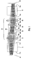
- An exemplary two-stage projection system as shown in Figure 1 , comprises a first imager 50 and a second imager 60, with two polarizing beam splitters (PBS's) 71, 72 and a lens set or lens system 80 disposed between the imagers 50, 60 to relay light images from the first imager 50 on a pixel-by-pixel basis onto corresponding pixels of the second imager 60.
- PBS's polarizing beam splitters
- exemplary relay lens system 80 comprises a first aspherical lens 81 and a first acromatic lens 82 between the first PBS 71 and the focal point of the lens system or system stop 83. Between the system stop 83 and the second imager 72, lens system 80 comprises a second acromatic lens 84 and a second aspherical lens 85.
- First aspherical lens 81 has a first surface 81a and second surface 81b which bend the diverging light pattern from the first PBS 71 into a light pattern converging toward the optical axis of lens system 80.
- First acromatic lens 82 has a first surface 82a, a second surface 82b, and a third surface 82c, which focus the converging light pattern from the first aspherical lens 81 onto the system stop 83. At the system stop 83, the light pattern inverts and diverges.
- the second acromatic lens 84 which has a first surface 84a, a second surface 84b, and a third surface 84c, is a mirror image of first acromatic lens 82 (i.e., the same lens turned backward such that first surface 84a of second acromatic lens 84 is equivalent to third surface 82c of first acromatic lens 82 and third surface 84c of second acromatic lens 84 is equivalent to first surface 82a of first acromatic lens 82).
- the surfaces 84a, 84b, and 84c of second acromatic lens 84 distribute the diverging light pattern onto the second aspherical lens 85.
- the second aspherical lens 85 which has a first surface 85a and a second surface 85b, is a mirror image of the first aspherical lens 81.
- Surfaces 85a and 85b bend the light pattern to converge to form an inverted image on the second imager 72 that has a one-to-one correspondence to the object or matrix of pixels from the first imager 50.
- the surfaces of relay lens system 80 are configured to work with the imagers 50, 60 and PBS's 71, 72 to achieve the one-to-one correspondence of the pixels of first imager 50 and second imager 60.
- a summary of the surfaces of an exemplary two-stage projection system 30 are provided in Table 1, and aspherical coefficients for surfaces 81a, 81b, 85a, and 85b are provided in Table 2.
- exemplary lens surfaces were developed by the inventors using ZEMAX TM software and novel characteristics determined by the inventors.
- Various modifications can be made to this exemplary projection system based on such factors as: cost, size, luminance levels, and other design factors.
- acromatic lenses 82 and 84 are equivalent and aspherical lenses 81 and 85 are equivalent. Therefore, fewer unique parts are required providing manufacturing efficiencies and reduced cost.
- the acromatic lenses 82, 84 of the exemplary lens system 80 comprise inexpensive optical glass (SF15 having a cost approximately 2.25 times the cost of BK7 and BAK2 having a cost approximately 1.85 times the cost of BK7).
- second PBS 72 After the first light matrix 5 leaves the relay lens system 80, it enters into a second PBS 72 through a first surface 72a.
- Second PBS 72 has a polarizing surface 72p that reflects the s-polarity first light matrix 5 through a second surface 72b onto the second imager 60.
- second imager 60 is an LCOS imager which modulates the previously modulated first light matrix 5 on a pixel-by-pixel basis proportional to a gray scale value provided to the second imager 60 for each individual pixel.
- the pixels of the second imager 60 correspond on a one-for-one basis with the pixels of the first imager 50 and with the pixels of the display image.
- the input of a particular pixel (i,j) to the second imager 60 is the output from corresponding pixel (i,j) of the first imager 50.
- the lens system 80 summarized in Tables 1 and 2 was designed using the ZEMET TM software package under system constraints devised by the inventors.
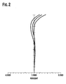
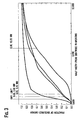
- the calculated distortion and the ensquared energy of the lens system 80 are shown in Figures 2 and 3 , respectively.
- the distortion is less than 0.015%, causing the light output from a particular pixel (i,j) in the first imager 50 to be relayed or projected onto a corresponding pixel (i,j) in the second imager 60, allowing a video image, for example, to be modulated by a combination of values provided to the first imager 50 and second imager 60 for that pixel (i,j).
- the light energy from the first imager 50 is highly ensquared, with at least 90% of the light energy output from a particular pixel (i,j) on the first imager 50 being projected onto a 15.4 micron square on the second imager 60. Since the pixel size for an exemplary LCOS imager is 12 microns, the majority of light from a particular pixel (i,j) on the first imager 50 will fall on the corresponding pixel (i,j) on the second imager 60.
- the magnification for a one-to-one lens system should be approximately -1.0 when the imagers 50, 60 are the same size to project an image from the first imager 50 onto the second imager 60 on a pixel-by-pixel basis.
- the exemplary lens system 80 provides a magnification of -0.99977 as calculated by the ZEMAX TM software.
- the exemplary lens system 80 also provides a low F-number of no greater than 2.8, and more particularly a calculated F-number of about 2.798. This low F-number is desired to ensure adequate illumination of the viewing screen.
- the exemplary lens system 80 is also compact, having an overall distance between imagers 50, 60 of about 161.25 mm. This overall length is a summation of the thickness values for the various surfaces of the lens system, the thickness values being the linear distance to the next surface.
- the lens system 80 must be highly telecentric.
- the calculated maximum deviations from the chief ray in the center of the projected image for the exemplary lens system 80 are 1.03 degrees of input angle and 1.00 degrees of output angle.
Abstract
Description
- The present invention is related generally to a lens system for use in a projection system and more particularly to a low distortion, 1-to-1 projection lens for projecting an image from a first imager onto a second imager in a two stage projector architecture.
- Liquid crystal displays (LCDs), and particularly liquid crystal on silicon (LCOS) systems using a reflective light engine or imager, are becoming increasingly prevalent in imaging devices such as rear projection television (RPTV). In an LCOS system, projected light is polarized by a polarizing beam splitter (PBS) and directed onto a LCOS imager or light engine comprising a matrix of pixels. Throughout this specification, and consistent with the practice of the relevant art, the term pixel is used to designate a small area or dot of an image, the corresponding portion of a light transmission, and the portion of an imager producing that light transmission.
- Each pixel of the imager modulates the light incident on it according to a gray-scale factor input to the imager or light engine to form a matrix of discrete modulated light signals or pixels. The matrix of modulated light signals is reflected or output from the imager and directed to a system of projection lenses which project the modulated light onto a display screen, combining the pixels of light to form a viewable image. In this system, the gray-scale variation from pixel to pixel is limited by the number of bits used to process the image signal. The contrast ratio from bright state (i.e., maximum light) to dark state (minimum light) is limited by the leakage of light in the imager.
- One of the major disadvantages of existing LCOS systems is the difficulty in reducing the amount of light in the dark state, and the resulting difficulty in providing outstanding contrast ratios. This is, in part, due to the leakage of light, inherent in LCOS systems.
- In addition, since the input is a fixed number of bits (e.g., 8, 10, etc.), which must describe the full scale of light, there tend to be very few bits available to describe subtle differences in darker areas of the picture. This can lead to contouring artifacts.
- One approach to enhance contrast in LCOS in the dark state is to use a COLORSWITCH™ or similar device to scale the entire picture based upon the maximum value in that particular frame. This improves some pictures, but does little for pictures that contain high and low light levels. Other attempts to solve the problem have been directed to making better imagers, etc. but these are at best incremental improvements.
- What is needed is a projection system that enhances the contrast ratio for video images, particularly in the dark state, and reduces contouring artifacts.
- The present invention is defined by the claims and provides a lens system configured to project an image from a first imager on a pixel-by-pixel basis onto a second imager in a two stage projector architecture. To project an image from a first imager on a pixel-by-pixel basis onto a second imager, a double-gauss lens system is provided according to an embodiment of the present invention having a distortion of less than about 0.015% and projecting at least about 90% of the light energy of a specific pixel on the first imager within about a 15.4 micrometer square on the second imager. In an exemplary embodiment of the invention, the magnification of the lens system is very precisely controlled at about -1 and telecentricity is maintained at both the input and the output of the lens system.
- The invention will now be described with reference to the accompanying figures, of which:
-
Figure 1 shows an exemplary lens system according to an embodiment of the present invention; -
Figure 2 shows the calculated distortion for the lens system ofFigure 1 ; and -
Figure 3 shows the calculated ensquared energy for the lens system ofFigure 1 . - The inventors have determined that, by projecting the output of a first imager onto a second imager such that the output of a particular pixel in the first imager is projected onto a corresponding pixel in the second imager, a projection system can be provided with enhanced contrast and reduced contouring. The inventors have determined that this two-stage architecture requires a lens system with very low distortion and highly ensquared energy. The light from a pixel on the first imager must be centered on its corresponding pixel. Also, most of the light must fall within the area of the corresponding pixel.
- The present invention provides a low-distortion, high-ensquared energy, relay lens system for use in a two-stage projection architecture. In an exemplary embodiment of the invention, a double gauss lens system is provided to relay light from a first imager to a
second imager 60 with distortion of less than 0.015% and at least 90% of the light energy from a specific pixel of thefirst imager 50 projected onto about a 15.4 micrometer square on the second imager. An exemplary two-stage projection system, as shown inFigure 1 , comprises afirst imager 50 and asecond imager 60, with two polarizing beam splitters (PBS's) 71, 72 and a lens set orlens system 80 disposed between theimagers first imager 50 on a pixel-by-pixel basis onto corresponding pixels of thesecond imager 60. - As shown in
Fig. 1 , exemplaryrelay lens system 80 comprises a firstaspherical lens 81 and a firstacromatic lens 82 between thefirst PBS 71 and the focal point of the lens system orsystem stop 83. Between the system stop 83 and thesecond imager 72,lens system 80 comprises a secondacromatic lens 84 and a secondaspherical lens 85. Firstaspherical lens 81 has afirst surface 81a andsecond surface 81b which bend the diverging light pattern from thefirst PBS 71 into a light pattern converging toward the optical axis oflens system 80. Firstacromatic lens 82 has afirst surface 82a, a second surface 82b, and a third surface 82c, which focus the converging light pattern from the firstaspherical lens 81 onto the system stop 83. At the system stop 83, the light pattern inverts and diverges. The secondacromatic lens 84, which has afirst surface 84a, asecond surface 84b, and athird surface 84c, is a mirror image of first acromatic lens 82 (i.e., the same lens turned backward such thatfirst surface 84a of secondacromatic lens 84 is equivalent to third surface 82c of firstacromatic lens 82 andthird surface 84c of secondacromatic lens 84 is equivalent tofirst surface 82a of first acromatic lens 82). Thesurfaces acromatic lens 84 distribute the diverging light pattern onto the secondaspherical lens 85. The secondaspherical lens 85, which has afirst surface 85a and asecond surface 85b, is a mirror image of the firstaspherical lens 81.Surfaces second imager 72 that has a one-to-one correspondence to the object or matrix of pixels from thefirst imager 50. The surfaces ofrelay lens system 80 are configured to work with theimagers first imager 50 andsecond imager 60. A summary of the surfaces of an exemplary two-stage projection system 30 are provided in Table 1, and aspherical coefficients forsurfaces relay lens system 80acromatic lenses aspherical lenses acromatic lenses exemplary lens system 80, comprise inexpensive optical glass (SF15 having a cost approximately 2.25 times the cost of BK7 and BAK2 having a cost approximately 1.85 times the cost of BK7). (SF15, BK7, and BAK2 are commercially available from the Schott Corporation of Yonkers, New York.)TABLE 1 (dimensions in mm) device surface type radius thickness glass diameter conic 50 object std infinity 11.25436 0 71 2nd (71b) std infinity 28 SF2 24.07539 0 71 3rd (71c) std infinity 11.44304 29.59782 0 81 1st (81a) evenasph 45.72373 11.60359 BAK2 40 -0.941321 81 2nd (81b) evenasph -29.74398 1.061985 40 -2.300802 82 1st (82a) std 16.45201 9.507266 BAK2 28 -0.003454099 82 2nd (82b) std 696.8212 6.993905 SF15 28 0 82 3rd (82c) std 10.75055 6.389217 14 0 83 stop std infinity 6.389217 10.09268 0 84 1st (84a) std -10.75055 6.993905 SF15 14 0 84 2nd (84b) std -696.8212 9.507266 BAK2 28 0 84 3rd (84c) std -16.45201 1.061985 28 -0.003454099 85 1st (85a) evenasph 29.74398 11.60359 BAK2 40 -2.300802 85 2nd (85b) evenasph -45.72373 11.44304 40 -0.941321 72 1st (72a) std infinity 28 SF2 31.9247 0 72 2nd (72b) std infinity 11.25436 25.06428 0 60 image std infinity 20.44114 0 TABLE 2 coefficient on: surfaces 85b surfaces 81b, 85a r2 -2.5672672e-005 -2.5672139e-005 r4 -3.6464646e-007 -4.6458644e-007 r6 -1.3360629e-009 -5.3232556e-010 r8 2.2079531e-012 9.3458426e-013 r10 4.0274312e-019 -2.9875722e-019 r12 3.2408025e-022 8.6192792e-022 r14 -4.2302691e-024 5.022829e-024 r16 -1.3350251e-026 1.9281194e-026 - After the first light matrix 5 leaves the
relay lens system 80, it enters into a second PBS 72 through afirst surface 72a.Second PBS 72 has a polarizing surface 72p that reflects the s-polarity first light matrix 5 through asecond surface 72b onto thesecond imager 60. In the exemplary embodiment, illustrated inFigure 1 ,second imager 60 is an LCOS imager which modulates the previously modulated first light matrix 5 on a pixel-by-pixel basis proportional to a gray scale value provided to thesecond imager 60 for each individual pixel. The pixels of thesecond imager 60 correspond on a one-for-one basis with the pixels of thefirst imager 50 and with the pixels of the display image. Thus, the input of a particular pixel (i,j) to thesecond imager 60 is the output from corresponding pixel (i,j) of thefirst imager 50. - The
lens system 80 summarized in Tables 1 and 2 was designed using the ZEMET™ software package under system constraints devised by the inventors. The calculated distortion and the ensquared energy of thelens system 80 are shown inFigures 2 and3 , respectively. The distortion is less than 0.015%, causing the light output from a particular pixel (i,j) in thefirst imager 50 to be relayed or projected onto a corresponding pixel (i,j) in thesecond imager 60, allowing a video image, for example, to be modulated by a combination of values provided to thefirst imager 50 andsecond imager 60 for that pixel (i,j). The light energy from thefirst imager 50 is highly ensquared, with at least 90% of the light energy output from a particular pixel (i,j) on thefirst imager 50 being projected onto a 15.4 micron square on thesecond imager 60. Since the pixel size for an exemplary LCOS imager is 12 microns, the majority of light from a particular pixel (i,j) on thefirst imager 50 will fall on the corresponding pixel (i,j) on thesecond imager 60. - The magnification for a one-to-one lens system should be approximately -1.0 when the
imagers first imager 50 onto thesecond imager 60 on a pixel-by-pixel basis. Theexemplary lens system 80 provides a magnification of -0.99977 as calculated by the ZEMAX™ software. - The
exemplary lens system 80 also provides a low F-number of no greater than 2.8, and more particularly a calculated F-number of about 2.798. This low F-number is desired to ensure adequate illumination of the viewing screen. Theexemplary lens system 80 is also compact, having an overall distance betweenimagers - Also, because the light input to the projection system is telecentric and the projection lens requires a telecentric image, the
lens system 80 must be highly telecentric. The calculated maximum deviations from the chief ray in the center of the projected image for theexemplary lens system 80 are 1.03 degrees of input angle and 1.00 degrees of output angle. - The foregoing illustrates some of the possibilities for practicing the invention. Many other embodiments are possible within the scope of the invention. It is, therefore, intended that the foregoing description be regarded as illustrative rather than limiting, and that the scope of the invention is given by the appended claims together with their full range of equivalents.
Claims (8)
- A projection system comprising a first imager (50), a second imager (60), and a lens system comprising a double gauss lens set for relaying light output from said first imager (50) on a pixel-by pixel basis onto said second imager (60) characterized in that said double gauss lens set consists of one pair of symmetrical acromatic lenses (82, 84) and one pair of symmetrical aspherical lenses (81, 85), and in that said imagers (50, 60) are LCOS imagers.
- The projection system of claim 1 characterized in that said double gauss lens set has a magnification of between about -0.9997 and -1.0003.
- The projection system of any one of claims 1 to 2 characterized in that said pair of symmetrical aspherical lenses (81, 85) are equivalent and surround said pair of symmetrical acromatic lenses (82, 84) and in that said pair of symmetrical acromatic lenses (82, 84) are equivalent.
- The projection system of any one of the preceding claims characterized in that it comprises two polarizing beam splitters (71, 72), a first one (71) between the first imager (50) and the entrance of said double gauss lens set, a second one (72) between the exit of said double gauss lens set and the second imager (60).
- The projection system of any one of the preceeding claims characterized in that said double gauss lens set has a telecentricity with an input and output angle deviation of less than 1.05 degrees.
- The projection system of any one of the preceeding claims characterized in that said lens set has a telecentricity with an input angle deviation of less than 1.03 degrees and an output angle deviation of less than 1.0 degrees.
- The projection system of any one of the preceeding claims characterized in that the total distance between the first (50) and second (60) imagers is less than 165 mm.
- The projection system of any one of the preceeding claims characterized in that the double gauss lens set has an F-number no greater than about 2.8.
Applications Claiming Priority (3)
| Application Number | Priority Date | Filing Date | Title |
|---|---|---|---|
| US43099502P | 2002-12-04 | 2002-12-04 | |
| US430995P | 2002-12-04 | ||
| PCT/US2003/038199 WO2004051362A2 (en) | 2002-12-04 | 2003-11-26 | Imager to imager relay lens system |
Publications (2)
| Publication Number | Publication Date |
|---|---|
| EP1579682A2 EP1579682A2 (en) | 2005-09-28 |
| EP1579682B1 true EP1579682B1 (en) | 2011-01-05 |
Family
ID=32469581
Family Applications (1)
| Application Number | Title | Priority Date | Filing Date |
|---|---|---|---|
| EP03790205A Expired - Fee Related EP1579682B1 (en) | 2002-12-04 | 2003-11-26 | Imager to imager relay lens system |
Country Status (11)
| Country | Link |
|---|---|
| US (1) | US7317578B2 (en) |
| EP (1) | EP1579682B1 (en) |
| JP (2) | JP2006509244A (en) |
| KR (1) | KR101047294B1 (en) |
| CN (1) | CN1717927B (en) |
| AU (1) | AU2003293213A1 (en) |
| BR (1) | BR0316337A (en) |
| DE (1) | DE60335659D1 (en) |
| MX (1) | MXPA05005802A (en) |
| TW (1) | TWI238905B (en) |
| WO (1) | WO2004051362A2 (en) |
Families Citing this family (20)
| Publication number | Priority date | Publication date | Assignee | Title |
|---|---|---|---|---|
| EP1836532A4 (en) * | 2005-01-12 | 2009-08-12 | Colorlink Inc | Illumination attenuation system |
| JP2009500660A (en) * | 2005-06-30 | 2009-01-08 | トムソン ライセンシング | High contrast transmissive LCD imager |
| JP4400550B2 (en) * | 2005-11-09 | 2010-01-20 | セイコーエプソン株式会社 | Image display device and projector |
| WO2008068257A1 (en) * | 2006-12-05 | 2008-06-12 | Thomson Licensing | Projection image display device having two modulation stages |
| WO2011160693A1 (en) * | 2010-06-24 | 2011-12-29 | Osram Ag | Light source unit with phosphor element |
| KR101249476B1 (en) * | 2011-07-20 | 2013-04-01 | 한국기초과학지원연구원 | Lens for ir-tv used for diagnosing plasma of kstar apparatus |
| WO2013070514A2 (en) | 2011-11-08 | 2013-05-16 | Reald Inc. | Imaging path speckle mitigation |
| JP6330286B2 (en) * | 2013-10-22 | 2018-05-30 | セイコーエプソン株式会社 | projector |
| US9188767B2 (en) * | 2013-11-04 | 2015-11-17 | Christie Digital Systems Usa, Inc. | Relay lens system for a high dynamic range projector |
| JP6471424B2 (en) * | 2013-11-13 | 2019-02-20 | セイコーエプソン株式会社 | projector |
| CN104536117B (en) * | 2014-11-28 | 2017-01-25 | 青岛市光电工程技术研究院 | Visible spectral relay imaging lens group |
| US9420202B1 (en) | 2015-04-01 | 2016-08-16 | Aviation Specialties Unlimited, Inc. | Compact intensified camera module |
| CA3030848A1 (en) * | 2016-07-15 | 2018-01-18 | Light Field Lab, Inc. | Energy propagation and transverse anderson localization with two-dimensional, light field and holographic relays |
| CN106646885B (en) * | 2016-12-30 | 2020-02-11 | 苏州苏大维格光电科技股份有限公司 | Projection objective and three-dimensional display device |
| CN106646884B (en) * | 2016-12-30 | 2020-03-20 | 苏州苏大维格光电科技股份有限公司 | Projection objective and three-dimensional display device |
| CN108254905B (en) * | 2017-12-20 | 2020-05-29 | 深圳市帅映科技股份有限公司 | Lens of 4K LCOS projection system |
| CN110764224B (en) * | 2018-07-27 | 2020-12-18 | 上海微电子装备(集团)股份有限公司 | Photoetching projection objective lens |
| US11442254B2 (en) | 2019-04-05 | 2022-09-13 | Inner Ray, Inc. | Augmented reality projection device |
| CN113834639A (en) * | 2021-09-29 | 2021-12-24 | 中国科学院长春光学精密机械与物理研究所 | Distortion eliminating ultramicro-nano optical system based on pixel-level polaroid |
| CN116027520B (en) * | 2023-03-30 | 2023-06-20 | 深圳市东正光学技术股份有限公司 | Optical imaging system and optical imaging apparatus |
Citations (2)
| Publication number | Priority date | Publication date | Assignee | Title |
|---|---|---|---|---|
| EP0829747A1 (en) * | 1996-09-11 | 1998-03-18 | Seos Displays Limited | Image display apparatus |
| WO2002011610A2 (en) * | 2000-08-10 | 2002-02-14 | Carl Zeiss | Visual field tester |
Family Cites Families (14)
| Publication number | Priority date | Publication date | Assignee | Title |
|---|---|---|---|---|
| US3391968A (en) * | 1964-07-09 | 1968-07-09 | Bausch & Lomb | Gauss type four member projection objective with finite conjugates and initial plano-parallel plate |
| JPS61289316A (en) * | 1985-06-15 | 1986-12-19 | Nippon Kogaku Kk <Nikon> | Variable power optical system |
| JP2548359B2 (en) * | 1989-03-01 | 1996-10-30 | 松下電器産業株式会社 | Projection lens and projection TV using it |
| JPH04127109A (en) * | 1990-06-13 | 1992-04-28 | Ricoh Co Ltd | Lens system for read |
| JPH06208055A (en) * | 1993-01-12 | 1994-07-26 | Nikon Corp | Projection lens system |
| JPH0843728A (en) * | 1994-07-27 | 1996-02-16 | Nec Corp | Projecting lens for liquid crystal projector and liquid crystal projector |
| DE4429194C2 (en) | 1994-08-18 | 2000-07-20 | Etb Endoskopische Technik Gmbh | Optical remodeling system on both sides |
| US5625495A (en) * | 1994-12-07 | 1997-04-29 | U.S. Precision Lens Inc. | Telecentric lens systems for forming an image of an object composed of pixels |
| US6198577B1 (en) | 1998-03-10 | 2001-03-06 | Glaxo Wellcome, Inc. | Doubly telecentric lens and imaging system for multiwell plates |
| US6339503B1 (en) * | 1998-11-06 | 2002-01-15 | Oni Systems Corp. | Optical interconnect using microlens/minilens relay |
| GB9828287D0 (en) * | 1998-12-23 | 1999-02-17 | Secr Defence Brit | Image display system |
| JP4077139B2 (en) * | 2000-06-16 | 2008-04-16 | 株式会社リコー | Image display device |
| JP2002116381A (en) * | 2000-10-11 | 2002-04-19 | Canon Inc | Original reading lens and original reader using the same |
| IL160902A0 (en) * | 2001-09-25 | 2004-08-31 | Cambridge Flat Projection | Flat-panel projection display |
-
2003
- 2003-11-26 DE DE60335659T patent/DE60335659D1/en not_active Expired - Lifetime
- 2003-11-26 MX MXPA05005802A patent/MXPA05005802A/en active IP Right Grant
- 2003-11-26 EP EP03790205A patent/EP1579682B1/en not_active Expired - Fee Related
- 2003-11-26 CN CN2003801041352A patent/CN1717927B/en not_active Expired - Fee Related
- 2003-11-26 WO PCT/US2003/038199 patent/WO2004051362A2/en active Application Filing
- 2003-11-26 JP JP2004557457A patent/JP2006509244A/en active Pending
- 2003-11-26 AU AU2003293213A patent/AU2003293213A1/en not_active Abandoned
- 2003-11-26 BR BR0316337-7A patent/BR0316337A/en not_active Application Discontinuation
- 2003-11-26 KR KR1020057010194A patent/KR101047294B1/en not_active IP Right Cessation
- 2003-11-26 US US10/537,185 patent/US7317578B2/en not_active Expired - Fee Related
- 2003-11-27 TW TW092133329A patent/TWI238905B/en not_active IP Right Cessation
-
2010
- 2010-07-01 JP JP2010150883A patent/JP2010237709A/en active Pending
Patent Citations (2)
| Publication number | Priority date | Publication date | Assignee | Title |
|---|---|---|---|---|
| EP0829747A1 (en) * | 1996-09-11 | 1998-03-18 | Seos Displays Limited | Image display apparatus |
| WO2002011610A2 (en) * | 2000-08-10 | 2002-02-14 | Carl Zeiss | Visual field tester |
Also Published As
| Publication number | Publication date |
|---|---|
| WO2004051362A2 (en) | 2004-06-17 |
| JP2010237709A (en) | 2010-10-21 |
| TW200420928A (en) | 2004-10-16 |
| CN1717927B (en) | 2010-04-28 |
| WO2004051362A3 (en) | 2004-09-02 |
| EP1579682A2 (en) | 2005-09-28 |
| DE60335659D1 (en) | 2011-02-17 |
| US20060082892A1 (en) | 2006-04-20 |
| TWI238905B (en) | 2005-09-01 |
| CN1717927A (en) | 2006-01-04 |
| AU2003293213A8 (en) | 2004-06-23 |
| US7317578B2 (en) | 2008-01-08 |
| JP2006509244A (en) | 2006-03-16 |
| KR20050085381A (en) | 2005-08-29 |
| BR0316337A (en) | 2005-09-27 |
| MXPA05005802A (en) | 2005-08-16 |
| AU2003293213A1 (en) | 2004-06-23 |
| KR101047294B1 (en) | 2011-07-11 |
Similar Documents
| Publication | Publication Date | Title |
|---|---|---|
| EP1579682B1 (en) | Imager to imager relay lens system | |
| KR101116248B1 (en) | 2 2 system for using larger arc lamps with smaller imagers in a two stage system comprising two imagers in series | |
| US7175279B2 (en) | Two-stage projection architecture | |
| EP2073050B1 (en) | Optical projection system having two sub-systems and forming an intermediate image there between | |
| EP1576829B1 (en) | Two-stage projector architecture | |
| US20090225236A1 (en) | High Contrast Transmissive Lcd Imager | |
| US7192139B2 (en) | High contrast stereoscopic projection system | |
| US5539580A (en) | Projection optical system for a liquid crystal projector | |
| CN109946815B (en) | Imaging optical system, projection display device, and imaging device | |
| US20070216872A1 (en) | Two- Stage Projector Architecture | |
| JPH0353221A (en) | Projection type color image display device | |
| WO2005096056A1 (en) | Anti-aliasing projection lens |
Legal Events
| Date | Code | Title | Description |
|---|---|---|---|
| PUAI | Public reference made under article 153(3) epc to a published international application that has entered the european phase |
Free format text: ORIGINAL CODE: 0009012 |
|
| 17P | Request for examination filed |
Effective date: 20050629 |
|
| AK | Designated contracting states |
Kind code of ref document: A2 Designated state(s): AT BE BG CH CY CZ DE DK EE ES FI FR GB GR HU IE IT LI LU MC NL PT RO SE SI SK TR |
|
| AX | Request for extension of the european patent |
Extension state: AL LT LV MK |
|
| RAP1 | Party data changed (applicant data changed or rights of an application transferred) |
Owner name: THOMSON LICENSING |
|
| DAX | Request for extension of the european patent (deleted) | ||
| RBV | Designated contracting states (corrected) |
Designated state(s): DE FR GB IT |
|
| 17Q | First examination report despatched |
Effective date: 20060612 |
|
| APBK | Appeal reference recorded |
Free format text: ORIGINAL CODE: EPIDOSNREFNE |
|
| APBN | Date of receipt of notice of appeal recorded |
Free format text: ORIGINAL CODE: EPIDOSNNOA2E |
|
| APBR | Date of receipt of statement of grounds of appeal recorded |
Free format text: ORIGINAL CODE: EPIDOSNNOA3E |
|
| APBV | Interlocutory revision of appeal recorded |
Free format text: ORIGINAL CODE: EPIDOSNIRAPE |
|
| GRAP | Despatch of communication of intention to grant a patent |
Free format text: ORIGINAL CODE: EPIDOSNIGR1 |
|
| RAP1 | Party data changed (applicant data changed or rights of an application transferred) |
Owner name: THOMSON LICENSING |
|
| GRAS | Grant fee paid |
Free format text: ORIGINAL CODE: EPIDOSNIGR3 |
|
| GRAA | (expected) grant |
Free format text: ORIGINAL CODE: 0009210 |
|
| AK | Designated contracting states |
Kind code of ref document: B1 Designated state(s): DE FR GB IT |
|
| REG | Reference to a national code |
Ref country code: GB Ref legal event code: FG4D |
|
| REF | Corresponds to: |
Ref document number: 60335659 Country of ref document: DE Date of ref document: 20110217 Kind code of ref document: P |
|
| REG | Reference to a national code |
Ref country code: DE Ref legal event code: R096 Ref document number: 60335659 Country of ref document: DE Effective date: 20110217 |
|
| REG | Reference to a national code |
Ref country code: DE Ref legal event code: R084 Ref document number: 60335659 Country of ref document: DE |
|
| PLBE | No opposition filed within time limit |
Free format text: ORIGINAL CODE: 0009261 |
|
| STAA | Information on the status of an ep patent application or granted ep patent |
Free format text: STATUS: NO OPPOSITION FILED WITHIN TIME LIMIT |
|
| 26N | No opposition filed |
Effective date: 20111006 |
|
| REG | Reference to a national code |
Ref country code: DE Ref legal event code: R097 Ref document number: 60335659 Country of ref document: DE Effective date: 20111006 |
|
| REG | Reference to a national code |
Ref country code: FR Ref legal event code: PLFP Year of fee payment: 13 |
|
| PGFP | Annual fee paid to national office [announced via postgrant information from national office to epo] |
Ref country code: DE Payment date: 20151126 Year of fee payment: 13 Ref country code: GB Payment date: 20151130 Year of fee payment: 13 Ref country code: IT Payment date: 20151124 Year of fee payment: 13 |
|
| PGFP | Annual fee paid to national office [announced via postgrant information from national office to epo] |
Ref country code: FR Payment date: 20151120 Year of fee payment: 13 |
|
| REG | Reference to a national code |
Ref country code: DE Ref legal event code: R119 Ref document number: 60335659 Country of ref document: DE |
|
| GBPC | Gb: european patent ceased through non-payment of renewal fee |
Effective date: 20161126 |
|
| REG | Reference to a national code |
Ref country code: FR Ref legal event code: ST Effective date: 20170731 |
|
| PG25 | Lapsed in a contracting state [announced via postgrant information from national office to epo] |
Ref country code: IT Free format text: LAPSE BECAUSE OF NON-PAYMENT OF DUE FEES Effective date: 20161126 Ref country code: FR Free format text: LAPSE BECAUSE OF NON-PAYMENT OF DUE FEES Effective date: 20161130 |
|
| PG25 | Lapsed in a contracting state [announced via postgrant information from national office to epo] |
Ref country code: GB Free format text: LAPSE BECAUSE OF NON-PAYMENT OF DUE FEES Effective date: 20161126 Ref country code: DE Free format text: LAPSE BECAUSE OF NON-PAYMENT OF DUE FEES Effective date: 20170601 |