EP1579206B1 - Verfahren und vorrichtung zum konstanthalten der haltezeiten in einer gaschromatographieanalyse - Google Patents
Verfahren und vorrichtung zum konstanthalten der haltezeiten in einer gaschromatographieanalyse Download PDFInfo
- Publication number
- EP1579206B1 EP1579206B1 EP03812641A EP03812641A EP1579206B1 EP 1579206 B1 EP1579206 B1 EP 1579206B1 EP 03812641 A EP03812641 A EP 03812641A EP 03812641 A EP03812641 A EP 03812641A EP 1579206 B1 EP1579206 B1 EP 1579206B1
- Authority
- EP
- European Patent Office
- Prior art keywords
- new
- old
- column
- pressure
- carrier gas
- Prior art date
- Legal status (The legal status is an assumption and is not a legal conclusion. Google has not performed a legal analysis and makes no representation as to the accuracy of the status listed.)
- Expired - Lifetime
Links
- 238000004458 analytical method Methods 0.000 title claims abstract description 46
- 238000000034 method Methods 0.000 title claims abstract description 39
- 230000014759 maintenance of location Effects 0.000 title claims abstract description 35
- 239000012159 carrier gas Substances 0.000 claims abstract description 61
- 239000000203 mixture Substances 0.000 claims abstract description 27
- 238000012360 testing method Methods 0.000 claims description 9
- 238000012986 modification Methods 0.000 claims description 7
- 230000004048 modification Effects 0.000 claims description 7
- 238000012545 processing Methods 0.000 claims description 3
- 239000000126 substance Substances 0.000 description 17
- 239000007789 gas Substances 0.000 description 7
- 238000001514 detection method Methods 0.000 description 5
- 238000005259 measurement Methods 0.000 description 5
- 230000005526 G1 to G0 transition Effects 0.000 description 4
- 230000001105 regulatory effect Effects 0.000 description 4
- 238000010586 diagram Methods 0.000 description 3
- 125000004432 carbon atom Chemical group C* 0.000 description 2
- 150000001875 compounds Chemical class 0.000 description 2
- 230000000875 corresponding effect Effects 0.000 description 2
- 230000001419 dependent effect Effects 0.000 description 2
- 238000011156 evaluation Methods 0.000 description 2
- 239000001307 helium Substances 0.000 description 2
- 229910052734 helium Inorganic materials 0.000 description 2
- SWQJXJOGLNCZEY-UHFFFAOYSA-N helium atom Chemical compound [He] SWQJXJOGLNCZEY-UHFFFAOYSA-N 0.000 description 2
- 229930195733 hydrocarbon Natural products 0.000 description 2
- 150000002430 hydrocarbons Chemical class 0.000 description 2
- 239000000243 solution Substances 0.000 description 2
- 238000013459 approach Methods 0.000 description 1
- 230000033228 biological regulation Effects 0.000 description 1
- 239000006227 byproduct Substances 0.000 description 1
- 230000015556 catabolic process Effects 0.000 description 1
- 239000000470 constituent Substances 0.000 description 1
- 230000001276 controlling effect Effects 0.000 description 1
- 230000002596 correlated effect Effects 0.000 description 1
- 238000006731 degradation reaction Methods 0.000 description 1
- 230000000694 effects Effects 0.000 description 1
- 230000003203 everyday effect Effects 0.000 description 1
- 239000008246 gaseous mixture Substances 0.000 description 1
- 238000002347 injection Methods 0.000 description 1
- 239000007924 injection Substances 0.000 description 1
- 238000013021 overheating Methods 0.000 description 1
- 238000000926 separation method Methods 0.000 description 1
- 230000002123 temporal effect Effects 0.000 description 1
Images


Classifications
-
- G—PHYSICS
- G01—MEASURING; TESTING
- G01N—INVESTIGATING OR ANALYSING MATERIALS BY DETERMINING THEIR CHEMICAL OR PHYSICAL PROPERTIES
- G01N30/00—Investigating or analysing materials by separation into components using adsorption, absorption or similar phenomena or using ion-exchange, e.g. chromatography or field flow fractionation
- G01N30/02—Column chromatography
- G01N30/26—Conditioning of the fluid carrier; Flow patterns
- G01N30/28—Control of physical parameters of the fluid carrier
- G01N30/32—Control of physical parameters of the fluid carrier of pressure or speed
-
- G—PHYSICS
- G01—MEASURING; TESTING
- G01N—INVESTIGATING OR ANALYSING MATERIALS BY DETERMINING THEIR CHEMICAL OR PHYSICAL PROPERTIES
- G01N30/00—Investigating or analysing materials by separation into components using adsorption, absorption or similar phenomena or using ion-exchange, e.g. chromatography or field flow fractionation
- G01N30/02—Column chromatography
- G01N30/86—Signal analysis
- G01N30/8665—Signal analysis for calibrating the measuring apparatus
- G01N30/8668—Signal analysis for calibrating the measuring apparatus using retention times
-
- G—PHYSICS
- G01—MEASURING; TESTING
- G01N—INVESTIGATING OR ANALYSING MATERIALS BY DETERMINING THEIR CHEMICAL OR PHYSICAL PROPERTIES
- G01N30/00—Investigating or analysing materials by separation into components using adsorption, absorption or similar phenomena or using ion-exchange, e.g. chromatography or field flow fractionation
- G01N30/02—Column chromatography
- G01N30/26—Conditioning of the fluid carrier; Flow patterns
- G01N30/28—Control of physical parameters of the fluid carrier
- G01N30/32—Control of physical parameters of the fluid carrier of pressure or speed
- G01N2030/324—Control of physical parameters of the fluid carrier of pressure or speed speed, flow rate
Definitions
- the present invention relates to a method for maintaining the retention times of the components of a mixture to be analysed constant in an apparatus for gaschromatographic analysis provided with a capillary column, when there is a variation in the length of said capillary column and/or a variation in the output pressure from said column.
- a known practice is to use a capillary column, having predefined stationary phase and nominal dimensions, in which the mixture to be analysed is made to pass in the gaseous state, by means of an inert carrier gas (carrier), at an appropriate temperature, or temperature profile in time, at which the column itself is kept.
- carrier inert carrier gas
- the various components have different times for traversing the capillary column as their own constituent parts vary, and hence the various substances reach a detector, set downstream of the column, in different times. There is thus obtained a separation in time of the components of the mixture which enables evaluation of the presence of each individual substance present.
- the said traversing times are referred to as retention times of the substances.
- chromatogram which shows a series of consecutive peaks.
- the peaks are plotted on a cartesian graph, on the ordinate of which is a scale of measurements proportional to the amount of the substance and on the abscissa of which is the time elapsing from introduction of the specimen into the apparatus.
- the retention time is characteristic for each substance and constitutes the parameter used for identification of the individual substance (component) that is detected.
- detectors downstream of the capillary column can operate at different pressures, and in particular it is common practice to use detectors that operate at atmospheric pressure and detectors that operate in the presence of a vacuum (mass spectrometer).
- the analysis of one and the same mixture of substances before and after the aforesaid modifications involves, all the other conditions being equal, the variation in the retention times, this resulting in the detriment of the identification of the components of the mixture under examination.
- the variation in the retention times thus imposes a recalibration of the apparatus and/or a modification of the parameters of analysis in order to render comparable the results obtained before and after said modifications, these being activities which involve, in common practice, a considerable expenditure in terms of time and resources.
- the patent EP-B-0.741.867 in the name of the present applicant, teaches how to measure experimentally, by means of a test with just the carrier, a constant K that is a function of the geometrical parameters of the column used in the apparatus for gaschromatographic analysis, for the purpose of providing a simple and reliable method for controlling the flow rate in the gaschromatographic apparatus itself.
- This patent right does not, however, contain any indications regarding the use of said constant K , defined also as the inverse of the pneumatic resistance of the column, in order to maintain the retention times constant as the geometrical parameters of the column vary or as the output pressure from the latter varies, said pressure being determined by the detector used for the analysis.
- a purpose of the present invention is to provide a method and an apparatus which, as the length of the column varies and/or the output pressure varies, enables the same retention times of the substances of a mixture to be obtained before and after said variation, in the case where the temperatures of the column are maintained the same, instant by instant, starting from when the specimen is introduced into the apparatus.
- Another purpose of the present invention is to provide a method and an apparatus that will enable, starting from simple measurements of the state of the system, precise values of pressure and/or of flow rate of the carrier gas to be obtained, which are to be set after a variation in length of the column and/or in the output pressure of the carrier gas, for the purpose of obtaining the aforesaid same retention times for the same substances, before and after said variations.
- the method for obtaining the reproducibility of the retention times of the components of a mixture to be analysed in an apparatus for gaschromatographic analysis provided with a capillary column when one of the following variations occurs: namely variation in the length of the column, or alternatively replacement of the column with a column having identical real specifications with the exception of the length, and/or variation in the pressure of the carrier gas at output from said column - envisages that the temperature or temperature profile will be maintained unvaried, instant by instant, starting from the introduction of the mixture to be analysed into the apparatus, for each analysis of the mixture.
- pneumatic resistance KC (KC old or KC new ) defined analytically above, and to which reference will be made in what follows, is for convenience of calculation the inverse of the constant K defined in the above-mentioned patent EP-B-0.741.867 , filed in the name of the present applicant.
- relation (xii) is valid only in the case where the analyses performed before and after the variation in length of the column and/or the variation in output pressure are performed, maintaining the actual diameter of the column and the temperature (T col ) of the column constant instant by instant (starting from introduction of the mixture to be analysed).
- the mass flow F depends strictly upon the temperature that the column assumes and consequently, in the case where for the analysis of a given specimen it were necessary to enter a program of temperatures in time, it would become necessary to calculate and control the new mass flow F new , instant by instant.
- relation (xiv) does not presuppose calculation instant by instant of the input pressure of the carrier gas to be set in the apparatus after the variation in length of the column and/or in the output pressure.
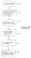
- the method envisages (step 101) recording, prior to the aforesaid variation or variations, the pressure of the carrier gas at input p i,old and the pressure of the gas at output p o,old , the latter depending upon the type of device for analysis that is set downstream of the capillary column.
- step 103 After the variations in the length of the column and/or in the output pressure (step 102), it is necessary to determine again (step 103) the constant of resistance of the column KC new .
- Said value KC new can be determined automatically by the apparatus for analysis, by means of, for example, a so-called blank test, i.e., by causing only carrier gas to flow, in stabilized conditions of flow rate, and subsequently measuring or setting the values T col , p i , F (and possibly p o if this is not known), according to relation (xiii).
- step 103 In the event of the variation undergone by the apparatus consisting only of the variation in output pressure, it would not be necessary to re-determine the constant KC of the column (which remains unvaried), and thus step 103 should not be executed.
- the method described can be implemented using the apparatus for gaschromatographic analysis represented schematically in Figure 3 , in which there are present, on the line for introduction of the carrier gas, a device 1 for detection of the input pressure of the carrier, and means 2 for regulating said pressure, as well as an injection system 3 for input of the mixture to be analysed, which at output directs the flow of gas towards a capillary column 6.
- the apparatus moreover comprises an oven 4, the temperature of which is regulated by a control device 5, and a capillary column 6 of length L or pneumatic resistance KC known, housed within the oven 4 itself. Downstream of the column 6, there is moreover present a detector 7 for the gases at output from the column, which is designed to measure the amount of the gases that flow from the column 6 itself.
- the apparatus moreover comprises storage and processing means 8 (usually an electronic processor), which interface both with the operator and with the device for detection of the pressure 1, and govern the control device 5 and the means 2 for regulation of the input pressure of the carrier.
- storage and processing means 8 usually an electronic processor
- the constant of resistance KC old of the column 6, is stored in these means 8, and the input pressure of the carrier gas p i,new is measured and stored.
- the electronic processor 8 calculates, via successive approximations, the new value p i,new that the input pressure of the carrier must assume so that the retention times will remain constant for each substance, and, when a new analysis is performed, sets said new pressure p i,new by acting on the means 2 for regulating the pressure of the carrier at input.
- the apparatus may comprise means for measuring the mass flow F of the carrier gas, possibly referred to standard conditions, and means for regulating this flow (not illustrated). There may likewise be provided a detector for detection of the output pressure of the carrier gas (not illustrated).
- Figure 2 illustrates, instead, a method for maintaining the retention times constant after variation in the length of the column and/or in the output pressure of the carrier, whereby it is envisaged to control the mass flow of the carrier and whereby the value KC old of the constant of resistance of the column is known.
- step 201 in which, prior to the variations of the apparatus, there is carried out the measurement of the input pressure p i,old of the carrier, of the output pressure p o,old (if it is not known already) and, unlike the method illustrated in Figure 1 , of the mass flow F old , referred to standard conditions.
- the latter detection as may readily be understood from the analysis of relation (xiii), can alternatively be replaced by measuring the temperature T col of the column in order to calculate the quantity F old itself. If the operation is carried out at constant flow, as the temperature T col varies also the input pressure p i will vary, which hence is to be calculated instant by instant.
- step 203 envisages redetermining the constant KC new only if the variation in length of the column has occurred, and step 204 envisages calculating the new mass flow F new (equation (xii)) under standard conditions, whereby constancy of the retention times is to be obtained.
- step 205 envisages this value F new being set into the apparatus for subsequent analyses.
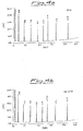
- the output pressure was equal to the atmospheric pressure (101 kPa), and the results of the analysis are represented in the chromatogram provided in Figure 4a (the ordinate represents an amount correlated to the amount of gas as it passes the detector downstream of the column, and the abscissa the time elapsed). Each of the peaks, which follow one another at determined time intervals, represents the measured amount of a certain component (see Table 1).
- the output pressure was not modified.
- Table 1 Component Retention times (original column) (min) Retention times (cut column) (min) Difference (absolute value) (min) C10 2.00 1.98 0.02 C12 4.38 4.35 0.03 C14 7.05 7.03 0.02 C16 9.57 9.55 0.02 C18 11.87 11.85 0.02 C20 13.96 13.94 0.02 C24 17.63 17.61 0.02 C30 22.19 22.19 0.00
- the results of the analysis are represented in the chromatogram provided in Figure 5a , and the numeric evaluation of the retention times is given in Table 2.
- MS mass spectrometer
- Table 2 Component Retention times (atmospheric-pressure detector (FID)) (min) Retention times (detector under vacuum conditions (MS)) (min) Difference (absolute value) (min) C10 2.10 2.12 0.02 C12 3.54 3.57 0.03 C14 4.99 5.02 0.03 C16 6.30 6.33 0.03 C18 7.49 7.51 0.02 C20 8.57 8.58 0.01 C24 10.46 10.47 0.01 C30 12.81 12.81 0.00
Landscapes
- Physics & Mathematics (AREA)
- Health & Medical Sciences (AREA)
- Life Sciences & Earth Sciences (AREA)
- Chemical & Material Sciences (AREA)
- Analytical Chemistry (AREA)
- Biochemistry (AREA)
- General Health & Medical Sciences (AREA)
- General Physics & Mathematics (AREA)
- Immunology (AREA)
- Pathology (AREA)
- Sampling And Sample Adjustment (AREA)
- Other Investigation Or Analysis Of Materials By Electrical Means (AREA)
- Investigating Or Analyzing Materials Using Thermal Means (AREA)
Claims (11)
- Verfahren, um die Reproduzierbarkeit der Haltezeiten der Bestandteile eines zu analysierenden Gemisches in einer Vorrichtung zur gaschromatographischen Analyse, bereitgestellt mit einer Kapillarsäule, zu erreichen, wenn eine oder mehrere der folgenden Variationen erfolgen: eine Variation der Säulenlänge oder alternativ ein Austausch der Säule durch eine Säule mit identischen realen Spezifikationen, mit Ausnahme der Länge, und/oder eine Variation des Austrittsdrucks aus dieser Säule, vorausgesetzt, dass der pneumatische Widerstand KGold = K(Lold) dieser Säule bekannt ist, dessen analytischer Ausdruck wie folgt lautet:
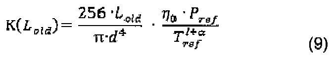
worin:d der Durchmesser der Säule ist;Pref beziehungsweise Tref der Referenzdruck und die Referenztemperatur sind (bezogen auf Standardbedingungen);η0 die Viskosität des Trägergases unter den Referenzbedingungen ist;Lold die initiale Länge der Säule ist;α der Koeffizient in Abhängigkeit vom Typ des verwendeten Trägergases ist;und wobei die Temperatur der Kapillarsäule fortwährend konstant gehalten wird, beginnend beim Einführen des Gemisches in die Vorrichtung, für die jeweilige Analyse dieses Gemisches vor und nach einer der Variationen, gekennzeichnet durch die folgenden Schritte:- Messung, bevor die Variationen erfolgen, des Drucks pi,old des Trägergases am Eingangsabschnitt der Säule, sowie des Drucks po,old des Trägergases am Austrittsabschnitt der Säule;- im Anschluss an die Variationen das Messen des neuen pneumatischen Widerstands KCnew = K(Lnew) der Säule, dessen analytischer Ausdruck wie folgt lautet:
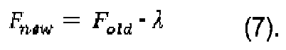
worin:Lnew die neue Länge der Säule ist;- Auswählen, nach erfolgten Variationen, des neuen Drucks po,new am Austritt der Säule;- Berechnen eines neuen Eingangsdrucks pi,new oder eines neuen Massenflusses Fnew (bezogen auf Standardbedingungen) des Trägergases, unter Verwendung der Beziehung:
worin:

 - Einstellen, nach erfolgten Variationen, des neuen Eingangsdrucks pi,new oder des neuen Massenflusses Fnew des Trägergases in der Vorrichtung zur gaschromatographischen Analyse in Korrelation zu λ.
 - Verfahren nach Anspruch 1, wobei das Verfahren die folgenden Schritte umfasst:- Speichern der bekannten Größen K(Lold), K(Lnew), pi,old, Po,old und po,new in einem elektronischen Speichermittel der Vorrichtung zur gaschromatographischen Analyse;- Speichern der Beziehung λ in dem elektronischen Speichermittel;- Verwendung von λ zur Berechnung und Eingabe der Größe Fnew oder Pi,new;- Bereitstellen von Hilfsmitteln zum Einstellen und Regeln des Eingangsdrucks pi,new und/oder der Flussrate Fnew in der Analysevorrichtung.
- Verfahren nach entweder Anspruch 1 oder Anspruch 2, wobei zur Berechnung des Eingangsdrucks pi,new die folgende Beziehung verwendet wird:

- Verfahren nach Anspruch 1 oder Anspruch 2, wobei zur Berechnung des Massenflusses Fnew die folgenden Schritte vorgesehen sind:- Messen des Massenflusses Fold, bezogen auf Standardbedingungen, des Trägergases, bevor die Variationen erfolgen;- Berechnen der Größe Fnew unter Verwendung der Beziehung:
- Verfahren nach entweder Anspruch 1 oder Anspruch 2, wobei zur Berechnung des Massenflusses Fnew die folgenden Schritte vorgesehen sind:- Messen, vor Erfolgen der Variationen, der Temperatur Tcol der Kapillarsäule;- Berechnung des Massenflusses Fold, bezogen auf Standardbedingungen, des Trägergases vor Erfolgen der Variationen, unter Verwendung der Beziehung:

worin:α der Koeffizient in Abhängigkeit von der Art des verwendeten Trägergases ist;KCold = K(Lold) der pneumatische Widerstand der Säule gemäß Beziehung (5) aus Anspruch 1 ist;- Berechnen der Größe Fnew unter Verwendung der Beziehung:
- Verfahren nach Anspruch 4 oder 5, wobei, falls die Temperatur der Kapillarsäule einem zeitlich veränderlichen Trend folgt, der Fluss Fold fortwährend gemessen oder berechnet wird und der Fluss Fnew fortwährend berechnet wird.
- Verfahren nach einem der vorhergehenden Ansprüche, wobei die Größen KCold = K(Lold) und KCnew = K(Lnew) durch Blindversuche der gaschromatographischen Vorrichtung gemessen werden.
- Vorrichtung zur gaschromatographischen Analyse, bereitgestellt mit einer Kapillarsäule, welche Variationen in der Säulenlänge erfahren kann oder durch eine Säule mit identischen realen Spezifikationen, mit Ausnahme der Länge, ausgetauscht werden kann, und umfassend:- Hilfsmittel zur Messung des Drucks pi,old des Trägergases am Eingangsabschnitt der Säule (pi,old, pi,new);- Hilfsmittel zur Messung des Drucks des Trägergases beim Austritt aus der Säule (po,old, Po,new);- Hilfsmittel zur Speicherung der gemessenen oder in jedem Fall bekannten Größen, der Druck des Trägergases am Eingang (pi,old) und der Druck des Trägergases am Austritt (po,old), sowie der Größen: pneumatischer Widerstand der nicht-modifizierten Säule K(Lold) und pneumatischer Widerstand der Säule nach Modifikation der Länge dieser Säule, K(Lnew);- Hilfsmittel zur Speicherung und Verarbeitung zwecks Berechnung eines neuen Eingangsdrucks (pi,new) oder eines neuen Massenflusses (Fnew), bezogen auf Standardbedingungen, des Trägergases, gemäß dem Verfahren nach einem der Ansprüche 1 bis 7; sowie- Hilfsmittel zum Einstellen und Regeln des Eingangsdrucks (pi,new) und/oder des Flusses (Fnew).
- Vorrichtung nach Anspruch 8, dadurch gekennzeichnet, dass selbige Hilfsmittel umfasst zur Messung des Massenflusses Fold oder Fnew.
- Vorrichtung nach entweder Anspruch 8 oder Anspruch 9, dadurch gekennzeichnet, dass die Hilfsmittel zum Einstellen und Regeln des Eingangsdrucks pi,new und/oder des Flusses Fnew mit den Hilfsmitteln zur Speicherung und Verarbeitung wirkverbunden sind.
- Vorrichtung nach einem der Ansprüche 8, 9 und 10, dadurch gekennzeichnet, dass selbige Hilfsmittel umfasst zur Speicherung der Größen po,old, dem bekannten Wert des Austrittsdrucks für die nicht-modifizierte Säule, sowie po,new, dem Wert des Drucks, eingestellt am Austritt, für die modifizierte Säule.
Applications Claiming Priority (3)
| Application Number | Priority Date | Filing Date | Title |
|---|---|---|---|
| ITMI20022605 | 2002-12-09 | ||
| IT002605A ITMI20022605A1 (it) | 2002-12-09 | 2002-12-09 | Metodo ed apparecchiatura per mantenere costanti i tempi di ritenzione nell'analisi gascromatografica. |
| PCT/IB2003/005706 WO2004053478A1 (en) | 2002-12-09 | 2003-12-05 | A method and apparatus for keeping constant the retention times in a gaschromatographic analysis |
Publications (2)
| Publication Number | Publication Date |
|---|---|
| EP1579206A1 EP1579206A1 (de) | 2005-09-28 |
| EP1579206B1 true EP1579206B1 (de) | 2012-06-20 |
Family
ID=32500559
Family Applications (1)
| Application Number | Title | Priority Date | Filing Date |
|---|---|---|---|
| EP03812641A Expired - Lifetime EP1579206B1 (de) | 2002-12-09 | 2003-12-05 | Verfahren und vorrichtung zum konstanthalten der haltezeiten in einer gaschromatographieanalyse |
Country Status (5)
| Country | Link |
|---|---|
| US (1) | US7396386B2 (de) |
| EP (1) | EP1579206B1 (de) |
| AU (1) | AU2003302811A1 (de) |
| IT (1) | ITMI20022605A1 (de) |
| WO (1) | WO2004053478A1 (de) |
Families Citing this family (4)
| Publication number | Priority date | Publication date | Assignee | Title |
|---|---|---|---|---|
| JP4589393B2 (ja) * | 2004-07-26 | 2010-12-01 | パーキンエルマー・ヘルス・サイエンシズ・インコーポレーテッド | クロマトグラフカラムを通して流れる流体を循環するためのシステム |
| CN100451645C (zh) * | 2004-07-26 | 2009-01-14 | 珀金埃尔默Las公司 | 用来调节流经色谱系统的流体的方法 |
| US7468095B2 (en) | 2005-05-12 | 2008-12-23 | Perkinelmer Las, Inc. | System for controlling flow into chromatographic column using transfer line impedance |
| US20110203346A1 (en) * | 2008-04-17 | 2011-08-25 | Dsm Ip Asstes B.V. | Comprehensive two-dimensional gas chromatography |
Family Cites Families (13)
| Publication number | Priority date | Publication date | Assignee | Title |
|---|---|---|---|---|
| US4994096A (en) * | 1989-05-09 | 1991-02-19 | Hewlett-Packard Co. | Gas chromatograph having integrated pressure programmer |
| IT1274775B (it) * | 1994-09-16 | 1997-07-24 | Fisons Instr Spa | Metodo e dispositivo per il controllo della portata di gas vettore in apparecchi gascromatografici |
| US5545252A (en) * | 1995-03-01 | 1996-08-13 | The Perkin-Elmer Corporation | Flow regulation in gas chromatograph |
| US5711786A (en) * | 1995-10-23 | 1998-01-27 | The Perkin-Elmer Corporation | Gas chromatographic system with controlled sample transfer |
| US5987959A (en) * | 1996-10-10 | 1999-11-23 | Hewlett-Packard Company | Automated retention time locking |
| US5670707A (en) | 1996-11-01 | 1997-09-23 | Varian Associates, Inc. | Calibration method for a chromatography column |
| US5915269A (en) * | 1997-04-15 | 1999-06-22 | The Perkin-Elmer Corporation | Method and apparatus to compensate for gas chromatograph column permeability |
| US5958246A (en) * | 1997-05-16 | 1999-09-28 | The Perkin-Elmer Corporation | Standardization of chromatographic systems |
| US6165251A (en) * | 1998-05-05 | 2000-12-26 | The United States Of America As Represented By The Administrator Of The U.S. Environmental Protection Agency | On-line gas chromatograph with sample preparation, concentration, and calibration apparatus for measuring trace organic species from combustor flue gas |
| US6036747A (en) | 1998-07-24 | 2000-03-14 | Hewlett-Packard Company | Column specific parameters for retention time locking in chromatography |
| IT1309602B1 (it) * | 1999-02-25 | 2002-01-24 | Thermoquest Italia Spa | Metodo ed apparecchio per il riallineamento dei picchi in analisigascromatografiche. |
| US6494078B1 (en) * | 2001-06-25 | 2002-12-17 | Agilent Technologies, Inc. | Retention-time locked comprehensive multidimensional gas chromatography |
| US7135056B2 (en) * | 2004-02-13 | 2006-11-14 | Agilent Technologies, Inc. | Method and system for sub-ambient pressure control for column head pressure in gas chromatography systems |
-
2002
- 2002-12-09 IT IT002605A patent/ITMI20022605A1/it unknown
-
2003
- 2003-12-05 EP EP03812641A patent/EP1579206B1/de not_active Expired - Lifetime
- 2003-12-05 AU AU2003302811A patent/AU2003302811A1/en not_active Abandoned
- 2003-12-05 US US10/537,768 patent/US7396386B2/en not_active Expired - Fee Related
- 2003-12-05 WO PCT/IB2003/005706 patent/WO2004053478A1/en not_active Ceased
Also Published As
| Publication number | Publication date |
|---|---|
| WO2004053478A1 (en) | 2004-06-24 |
| US7396386B2 (en) | 2008-07-08 |
| EP1579206A1 (de) | 2005-09-28 |
| ITMI20022605A1 (it) | 2004-06-10 |
| AU2003302811A1 (en) | 2004-06-30 |
| US20060123987A1 (en) | 2006-06-15 |
Similar Documents
| Publication | Publication Date | Title |
|---|---|---|
| JP4360700B2 (ja) | ターゲットクロマトグラフィックシステムを表す仮想クロマトグラフシステムを求める方法、ターゲットクロマトグラフィックシステムのカラム温度を較正する方法、ターゲットクロマトグラフィックシステムを確認する方法 | |
| US5122746A (en) | Hydrocarbon gas measurements using nuclear magnetic resonance | |
| CA1319030C (en) | Control arrangement for the chromatography of liquids | |
| DE19534775C2 (de) | Verfahren zum Korrigieren der Fluß- und Drucksensordrift in einem Gaschromatographen | |
| US7691181B2 (en) | System for controlling flow into chromatographic column using transfer line impedance | |
| US8343258B2 (en) | Apparatus and method for controlling constant mass flow to gas chromatography column | |
| JP3775541B2 (ja) | クロマトグラフィーカラム用のキャリブレーション方法 | |
| US4927532A (en) | Device for the compensation of the baseline drift of a chromatographic separating column | |
| JP4343284B2 (ja) | ガスクロマトグラフシステムの保持時間の予測方法 | |
| US20140067304A1 (en) | Gas chromatograph data processing device, recording medium recording data processing program, and data processing method | |
| EP1579206B1 (de) | Verfahren und vorrichtung zum konstanthalten der haltezeiten in einer gaschromatographieanalyse | |
| EP1041382B1 (de) | Verfahren und Vorrichtung zum Wiederausrichten von Signalspitzen in Gaschromatographischen Analysen | |
| US20140309946A1 (en) | Data processing device for gas chromatograph, data processing method, and recording medium that stores data processing program | |
| US6036747A (en) | Column specific parameters for retention time locking in chromatography | |
| JP4507962B2 (ja) | ガスクロマトグラフ装置 | |
| EP4449112B1 (de) | Automatische leckerkennung | |
| Mattson et al. | Programming Techniques for Obtaining Maximum Sensitivity in the Real-Time Detection of GC Effluents | |
| JP2005345452A (ja) | ガスクロマトグラフ測定方法 | |
| JP2008267957A (ja) | ガスクロマトグラフ、ガスクロマトグラフ質量分析計、およびカラム長さ測定方法 | |
| JPH09297129A (ja) | クロマトグラフ用データ処理装置 | |
| JP3180010B2 (ja) | クロマトグラフ分析装置 | |
| JPS6129763A (ja) | 保持時間補正機能付きガスクロマトグラフ | |
| JPH07151745A (ja) | ガスクロマトグラフにおけるガス濃度測定方法 | |
| Hinshaw | Basic GC Measurements and Calculations | |
| JPH0688813A (ja) | ガスクロマトグラフ |
Legal Events
| Date | Code | Title | Description |
|---|---|---|---|
| PUAI | Public reference made under article 153(3) epc to a published international application that has entered the european phase |
Free format text: ORIGINAL CODE: 0009012 |
|
| 17P | Request for examination filed |
Effective date: 20050530 |
|
| AK | Designated contracting states |
Kind code of ref document: A1 Designated state(s): AT BE BG CH CY CZ DE DK EE ES FI FR GB GR HU IE IT LI LU MC NL PT RO SE SI SK TR |
|
| AX | Request for extension of the european patent |
Extension state: AL LT LV MK |
|
| DAX | Request for extension of the european patent (deleted) | ||
| RAP1 | Party data changed (applicant data changed or rights of an application transferred) |
Owner name: THERMO FISHER SCIENTIFIC S.P.A |
|
| 17Q | First examination report despatched |
Effective date: 20101124 |
|
| GRAP | Despatch of communication of intention to grant a patent |
Free format text: ORIGINAL CODE: EPIDOSNIGR1 |
|
| GRAS | Grant fee paid |
Free format text: ORIGINAL CODE: EPIDOSNIGR3 |
|
| GRAA | (expected) grant |
Free format text: ORIGINAL CODE: 0009210 |
|
| AK | Designated contracting states |
Kind code of ref document: B1 Designated state(s): AT BE BG CH CY CZ DE DK EE ES FI FR GB GR HU IE IT LI LU MC NL PT RO SE SI SK TR |
|
| REG | Reference to a national code |
Ref country code: GB Ref legal event code: FG4D |
|
| REG | Reference to a national code |
Ref country code: CH Ref legal event code: EP |
|
| REG | Reference to a national code |
Ref country code: AT Ref legal event code: REF Ref document number: 563331 Country of ref document: AT Kind code of ref document: T Effective date: 20120715 |
|
| REG | Reference to a national code |
Ref country code: IE Ref legal event code: FG4D |
|
| REG | Reference to a national code |
Ref country code: DE Ref legal event code: R096 Ref document number: 60341368 Country of ref document: DE Effective date: 20120816 |
|
| PG25 | Lapsed in a contracting state [announced via postgrant information from national office to epo] |
Ref country code: SE Free format text: LAPSE BECAUSE OF FAILURE TO SUBMIT A TRANSLATION OF THE DESCRIPTION OR TO PAY THE FEE WITHIN THE PRESCRIBED TIME-LIMIT Effective date: 20120620 Ref country code: FI Free format text: LAPSE BECAUSE OF FAILURE TO SUBMIT A TRANSLATION OF THE DESCRIPTION OR TO PAY THE FEE WITHIN THE PRESCRIBED TIME-LIMIT Effective date: 20120620 |
|
| REG | Reference to a national code |
Ref country code: NL Ref legal event code: VDEP Effective date: 20120620 |
|
| REG | Reference to a national code |
Ref country code: AT Ref legal event code: MK05 Ref document number: 563331 Country of ref document: AT Kind code of ref document: T Effective date: 20120620 |
|
| PG25 | Lapsed in a contracting state [announced via postgrant information from national office to epo] |
Ref country code: SI Free format text: LAPSE BECAUSE OF FAILURE TO SUBMIT A TRANSLATION OF THE DESCRIPTION OR TO PAY THE FEE WITHIN THE PRESCRIBED TIME-LIMIT Effective date: 20120620 Ref country code: GR Free format text: LAPSE BECAUSE OF FAILURE TO SUBMIT A TRANSLATION OF THE DESCRIPTION OR TO PAY THE FEE WITHIN THE PRESCRIBED TIME-LIMIT Effective date: 20120921 |
|
| PG25 | Lapsed in a contracting state [announced via postgrant information from national office to epo] |
Ref country code: EE Free format text: LAPSE BECAUSE OF FAILURE TO SUBMIT A TRANSLATION OF THE DESCRIPTION OR TO PAY THE FEE WITHIN THE PRESCRIBED TIME-LIMIT Effective date: 20120620 Ref country code: SK Free format text: LAPSE BECAUSE OF FAILURE TO SUBMIT A TRANSLATION OF THE DESCRIPTION OR TO PAY THE FEE WITHIN THE PRESCRIBED TIME-LIMIT Effective date: 20120620 Ref country code: RO Free format text: LAPSE BECAUSE OF FAILURE TO SUBMIT A TRANSLATION OF THE DESCRIPTION OR TO PAY THE FEE WITHIN THE PRESCRIBED TIME-LIMIT Effective date: 20120620 Ref country code: AT Free format text: LAPSE BECAUSE OF FAILURE TO SUBMIT A TRANSLATION OF THE DESCRIPTION OR TO PAY THE FEE WITHIN THE PRESCRIBED TIME-LIMIT Effective date: 20120620 Ref country code: CY Free format text: LAPSE BECAUSE OF FAILURE TO SUBMIT A TRANSLATION OF THE DESCRIPTION OR TO PAY THE FEE WITHIN THE PRESCRIBED TIME-LIMIT Effective date: 20120620 Ref country code: BE Free format text: LAPSE BECAUSE OF FAILURE TO SUBMIT A TRANSLATION OF THE DESCRIPTION OR TO PAY THE FEE WITHIN THE PRESCRIBED TIME-LIMIT Effective date: 20120620 Ref country code: CZ Free format text: LAPSE BECAUSE OF FAILURE TO SUBMIT A TRANSLATION OF THE DESCRIPTION OR TO PAY THE FEE WITHIN THE PRESCRIBED TIME-LIMIT Effective date: 20120620 |
|
| PG25 | Lapsed in a contracting state [announced via postgrant information from national office to epo] |
Ref country code: PT Free format text: LAPSE BECAUSE OF FAILURE TO SUBMIT A TRANSLATION OF THE DESCRIPTION OR TO PAY THE FEE WITHIN THE PRESCRIBED TIME-LIMIT Effective date: 20121022 Ref country code: IT Free format text: LAPSE BECAUSE OF FAILURE TO SUBMIT A TRANSLATION OF THE DESCRIPTION OR TO PAY THE FEE WITHIN THE PRESCRIBED TIME-LIMIT Effective date: 20120620 |
|
| PG25 | Lapsed in a contracting state [announced via postgrant information from national office to epo] |
Ref country code: NL Free format text: LAPSE BECAUSE OF FAILURE TO SUBMIT A TRANSLATION OF THE DESCRIPTION OR TO PAY THE FEE WITHIN THE PRESCRIBED TIME-LIMIT Effective date: 20120620 |
|
| PLBE | No opposition filed within time limit |
Free format text: ORIGINAL CODE: 0009261 |
|
| STAA | Information on the status of an ep patent application or granted ep patent |
Free format text: STATUS: NO OPPOSITION FILED WITHIN TIME LIMIT |
|
| PG25 | Lapsed in a contracting state [announced via postgrant information from national office to epo] |
Ref country code: ES Free format text: LAPSE BECAUSE OF FAILURE TO SUBMIT A TRANSLATION OF THE DESCRIPTION OR TO PAY THE FEE WITHIN THE PRESCRIBED TIME-LIMIT Effective date: 20121001 Ref country code: DK Free format text: LAPSE BECAUSE OF FAILURE TO SUBMIT A TRANSLATION OF THE DESCRIPTION OR TO PAY THE FEE WITHIN THE PRESCRIBED TIME-LIMIT Effective date: 20120620 |
|
| 26N | No opposition filed |
Effective date: 20130321 |
|
| REG | Reference to a national code |
Ref country code: DE Ref legal event code: R097 Ref document number: 60341368 Country of ref document: DE Effective date: 20130321 |
|
| PG25 | Lapsed in a contracting state [announced via postgrant information from national office to epo] |
Ref country code: BG Free format text: LAPSE BECAUSE OF FAILURE TO SUBMIT A TRANSLATION OF THE DESCRIPTION OR TO PAY THE FEE WITHIN THE PRESCRIBED TIME-LIMIT Effective date: 20120920 Ref country code: MC Free format text: LAPSE BECAUSE OF NON-PAYMENT OF DUE FEES Effective date: 20121231 |
|
| REG | Reference to a national code |
Ref country code: CH Ref legal event code: PL |
|
| GBPC | Gb: european patent ceased through non-payment of renewal fee |
Effective date: 20121205 |
|
| REG | Reference to a national code |
Ref country code: IE Ref legal event code: MM4A |
|
| REG | Reference to a national code |
Ref country code: FR Ref legal event code: ST Effective date: 20130830 |
|
| PG25 | Lapsed in a contracting state [announced via postgrant information from national office to epo] |
Ref country code: LI Free format text: LAPSE BECAUSE OF NON-PAYMENT OF DUE FEES Effective date: 20121231 Ref country code: CH Free format text: LAPSE BECAUSE OF NON-PAYMENT OF DUE FEES Effective date: 20121231 Ref country code: IE Free format text: LAPSE BECAUSE OF NON-PAYMENT OF DUE FEES Effective date: 20121205 |
|
| PG25 | Lapsed in a contracting state [announced via postgrant information from national office to epo] |
Ref country code: FR Free format text: LAPSE BECAUSE OF NON-PAYMENT OF DUE FEES Effective date: 20130102 Ref country code: GB Free format text: LAPSE BECAUSE OF NON-PAYMENT OF DUE FEES Effective date: 20121205 |
|
| REG | Reference to a national code |
Ref country code: DE Ref legal event code: R082 Ref document number: 60341368 Country of ref document: DE Representative=s name: GODEMEYER BLUM LENZE PARTNERSCHAFT, PATENTANWA, DE Ref country code: DE Ref legal event code: R082 Ref document number: 60341368 Country of ref document: DE Representative=s name: GODEMEYER BLUM LENZE - WERKPATENT, DE Ref country code: DE Ref legal event code: R082 Ref document number: 60341368 Country of ref document: DE Representative=s name: GODEMEYER BLUM LENZE PATENTANWAELTE, PARTNERSC, DE |
|
| PG25 | Lapsed in a contracting state [announced via postgrant information from national office to epo] |
Ref country code: TR Free format text: LAPSE BECAUSE OF FAILURE TO SUBMIT A TRANSLATION OF THE DESCRIPTION OR TO PAY THE FEE WITHIN THE PRESCRIBED TIME-LIMIT Effective date: 20120620 |
|
| PG25 | Lapsed in a contracting state [announced via postgrant information from national office to epo] |
Ref country code: LU Free format text: LAPSE BECAUSE OF NON-PAYMENT OF DUE FEES Effective date: 20121205 |
|
| PG25 | Lapsed in a contracting state [announced via postgrant information from national office to epo] |
Ref country code: HU Free format text: LAPSE BECAUSE OF FAILURE TO SUBMIT A TRANSLATION OF THE DESCRIPTION OR TO PAY THE FEE WITHIN THE PRESCRIBED TIME-LIMIT Effective date: 20031205 |
|
| PGFP | Annual fee paid to national office [announced via postgrant information from national office to epo] |
Ref country code: DE Payment date: 20211102 Year of fee payment: 19 |
|
| P01 | Opt-out of the competence of the unified patent court (upc) registered |
Effective date: 20230520 |
|
| REG | Reference to a national code |
Ref country code: DE Ref legal event code: R119 Ref document number: 60341368 Country of ref document: DE |
|
| PG25 | Lapsed in a contracting state [announced via postgrant information from national office to epo] |
Ref country code: DE Free format text: LAPSE BECAUSE OF NON-PAYMENT OF DUE FEES Effective date: 20230701 |