EP1579078B1 - Procede et appareil de recuperation des polluants dans une masse d'eau - Google Patents
Procede et appareil de recuperation des polluants dans une masse d'eau Download PDFInfo
- Publication number
- EP1579078B1 EP1579078B1 EP02731048A EP02731048A EP1579078B1 EP 1579078 B1 EP1579078 B1 EP 1579078B1 EP 02731048 A EP02731048 A EP 02731048A EP 02731048 A EP02731048 A EP 02731048A EP 1579078 B1 EP1579078 B1 EP 1579078B1
- Authority
- EP
- European Patent Office
- Prior art keywords
- water
- collection vessel
- pollutants
- separation compartment
- surface layer
- Prior art date
- Legal status (The legal status is an assumption and is not a legal conclusion. Google has not performed a legal analysis and makes no representation as to the accuracy of the status listed.)
- Expired - Lifetime
Links
- XLYOFNOQVPJJNP-UHFFFAOYSA-N water Substances O XLYOFNOQVPJJNP-UHFFFAOYSA-N 0.000 title claims abstract description 127
- 239000003344 environmental pollutant Substances 0.000 title claims abstract description 51
- 231100000719 pollutant Toxicity 0.000 title claims abstract description 51
- 238000000034 method Methods 0.000 title claims description 16
- 238000000926 separation method Methods 0.000 claims abstract description 35
- 239000002344 surface layer Substances 0.000 claims abstract description 34
- 239000010410 layer Substances 0.000 claims abstract description 30
- 239000006228 supernatant Substances 0.000 claims abstract 4
- 238000012544 monitoring process Methods 0.000 claims description 7
- 238000005303 weighing Methods 0.000 claims description 4
- 230000000977 initiatory effect Effects 0.000 claims description 3
- 238000005259 measurement Methods 0.000 claims description 3
- 239000007788 liquid Substances 0.000 description 6
- 239000000463 material Substances 0.000 description 5
- 239000002245 particle Substances 0.000 description 4
- 238000005086 pumping Methods 0.000 description 3
- 238000013459 approach Methods 0.000 description 2
- 229940077918 d-cal Drugs 0.000 description 2
- 230000007423 decrease Effects 0.000 description 2
- 239000000203 mixture Substances 0.000 description 2
- 239000003305 oil spill Substances 0.000 description 2
- 239000007787 solid Substances 0.000 description 2
- 239000000725 suspension Substances 0.000 description 2
- 230000006978 adaptation Effects 0.000 description 1
- 230000005540 biological transmission Effects 0.000 description 1
- 238000004140 cleaning Methods 0.000 description 1
- 238000004891 communication Methods 0.000 description 1
- 230000001419 dependent effect Effects 0.000 description 1
- 238000001514 detection method Methods 0.000 description 1
- 230000002706 hydrostatic effect Effects 0.000 description 1
- 238000007654 immersion Methods 0.000 description 1
- 230000002093 peripheral effect Effects 0.000 description 1
- 238000002360 preparation method Methods 0.000 description 1
- 238000012545 processing Methods 0.000 description 1
- 230000002441 reversible effect Effects 0.000 description 1
- 239000004576 sand Substances 0.000 description 1
- 239000003403 water pollutant Substances 0.000 description 1
Images

Classifications
-
- E—FIXED CONSTRUCTIONS
- E02—HYDRAULIC ENGINEERING; FOUNDATIONS; SOIL SHIFTING
- E02B—HYDRAULIC ENGINEERING
- E02B15/00—Cleaning or keeping clear the surface of open water; Apparatus therefor
- E02B15/04—Devices for cleaning or keeping clear the surface of open water from oil or like floating materials by separating or removing these materials
- E02B15/10—Devices for removing the material from the surface
- E02B15/106—Overflow skimmers with suction heads; suction heads
-
- Y—GENERAL TAGGING OF NEW TECHNOLOGICAL DEVELOPMENTS; GENERAL TAGGING OF CROSS-SECTIONAL TECHNOLOGIES SPANNING OVER SEVERAL SECTIONS OF THE IPC; TECHNICAL SUBJECTS COVERED BY FORMER USPC CROSS-REFERENCE ART COLLECTIONS [XRACs] AND DIGESTS
- Y10—TECHNICAL SUBJECTS COVERED BY FORMER USPC
- Y10S—TECHNICAL SUBJECTS COVERED BY FORMER USPC CROSS-REFERENCE ART COLLECTIONS [XRACs] AND DIGESTS
- Y10S210/00—Liquid purification or separation
- Y10S210/918—Miscellaneous specific techniques
- Y10S210/922—Oil spill cleanup, e.g. bacterial
- Y10S210/923—Oil spill cleanup, e.g. bacterial using mechanical means, e.g. skimmers, pump
Definitions
- a known method for collecting pollutants having a density higher than that of water and carried by a surface layer of a body of water uses a skimmer apparatus, that is, an apparatus by which the surface layer of the body of water is skimmed off into a collection vessel.
- a skimmer apparatus that is, an apparatus by which the surface layer of the body of water is skimmed off into a collection vessel.
- An example is shown in WO01/12905 A1 , which corresponds to the preamble of claims 1, 2, 6 and 7.
- the method is cyclical with each cycle of operation comprising an intake phase and a discharge phase.
- the surface layer runs into a collection vessel having a separation compartment with a top wall.
- the inflow into the collection vessel takes place through an inlet that communicates with the separation compartment.
- the pollutants entrained by the inflowing surface layer are allowed to collect gravimetrically, that is, by virtue of their lower density, to form a layer of pollutants beneath the top wall of the separation compartment. This layer floats on the underlying water in the separation compartment.
- the layer of pollutants collected beneath the top wall of the separation compartment is dispelled from the separation compartment through a riser outlet by introducing water as a displacing liquid into the separation compartment beneath the layer of pollutants.
- the skimmer apparatus by means of which the method is implemented operates automatically, the intake and discharge phases being initiated and terminated under control based on sensing the interfaces between the pollutant and water layers in the separation compartment and in the riser outlet.
- the sensing is carried out using ultrasonic sensors, but other types of sensors may also be used.
- the pollutants often comprise a mixture of solid and liquid pollutants and may comprise components having a density higher than that of the water in the skimmed surface layer and components having a lower density than the water.
- Ultrasonic sensors may operate in an excellent manner if they are properly set for the layers on which the sound is to be reflected or which the sound is to penetrate, but if the density or sonic transmission properties of the layer should change, the setting of the sensor has to be changed. If particles enter the region of the sensors, the function is affected in an unpredictable manner.
- skimmed surface layer often contains material that has a higher density than the water of the surface layer but is nevertheless entrained by the surface layer and carried into the collection vessel.
- this material may settle because of the low flow velocities which exist therein, especially in the separation compartment. The settled material may collect on the bottom wall of the separation compartment and gradually load the collection vessel heavily enough to jeopardize the function of the skimmer apparatus.
- the problem to be solved by the invention is to provide a method of the kind indicated in which the initiation and termination of the intake and discharge phases can be controlled reliably in a satisfactory manner.
- the solution to this problem is based on monitoring the changes of the weight of the collection vessel in the body of water during the operating cycle and initiating the intake and discharge phases in response to the said weight reaching predetermined values. These changes can be monitored in different ways.
- One way is to measure the distance between the surface of the body of water and a reference point which is fixed relative to the collection vessel and situated above the surface of the body of water.
- the changes manifest themselves by changes in the depth of immersion of the collection vessel.
- the distance measurement can be carried out using an echo sounder, for example.
- Another way is to directly measure the weight of the collection vessel in the body of water using a load cell.
- the invention also relates to apparatus for the implementation of the method according to the invention and to a software product which is made especially for use in carrying out the method according to the invention using a computer and auxiliary means coacting with it.
- Use of this software product may take place exclusively locally in the collection apparatus using a computer installed therein or via a communication link using a server which is geographically separated from the collection apparatus, such as a server which can be accessed via the Internet.
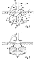
- Figs. 1 to 3 are vertical sectional views illustrating different phases of a cycle of operation of a known skimmer apparatus of the kind with which the invention is concerned, Fig. 1 showing an initial part of an intake phase, Fig. 2 showing a final part of the intake phase and Fig. 3 showing a part of a discharge phase;
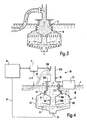
- Fig. 4 illustrates the skimmer apparatus of Fig. 1 provided with means for implementing the method according to the invention, namely in a situation when the apparatus has been deployed in a body of water but is not yet in operation;
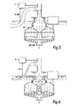
- Figs. 5 to 8 show different sequential steps in the preparation of the apparatus for operation in a body of water from which pollutant material is to be collected;
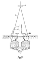
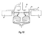
- Figs. 9 and 10 show two modified forms of the skimmer apparatus of Fig. 4
- the skimmer apparatus 10 diagrammatically shown in Figs. 1 to 3 is constructed substantially in accordance with WO01/ 12095 A1 and will be described here only to the extent necessary for the understanding of the present invention.
- the skimmer apparatus 10 comprises a collection vessel 11, which is designed in operation to be immersed in the body of water M the surface layer Y of which carries the pollutants to be collected and disposed of with the aid of the skimmer apparatus.
- An annular intake member 12 in the collection vessel 11 is formed by a buoyant ring the crest K of which defines an overflow inlet I and the lover side of which merges with or is attached to the upper end of an upstanding annular accordion-type bellows 13. At its lower end, this bellows is attached to the inner edge of an annular diaphragm disk 14, an outer edge of which is attached to the upper edge of a bowl-shaped, rigid container section 15.
- An upstanding conduit element 16 is centrally located in the container section 15 and stationary with respect to the latter.
- a funnel-shaped upper part 16A of the conduit element 16 is connected with a tubular lower part 16B, the lower end of which merges with an obliquely upwardly and outwardly directed annular flange 16C.
- a stationary horizontal plate 17 is mounted in the container section 15 and slightly spaced downwardly from the conduit element 16. The peripheral edge of the plate and the wall of the container section 15 define an annular gap.
- a reversible pump 18 (symbolically illustrated as a propeller) driven by an electric motor is mounted to pump water in both directions between the interior of the collection vessel 11 and the surrounding body M of water.
- the speed of the pump that is, the rotational speed of its motor, is variable.
- the annular diaphragm disk 14 forms a valve member which coacts with the upper edge of the funnel-shaped upper part 16A of the conduit element 16 so as in a closed position, shown in Figs. 1 and 2 , to block a throughflow passage R between the interior of the bellows 13 and the space, hereinafter designated as the separation compartment F, in the container section which surrounds the conduit element 16 and in an open position, shown in Fig. 3 , to allow flow through that passage R from the separation compartment F to the interior of the bellows 13.
- an outlet member 19 which is mounted in a manner not shown in Fig. 3 to be stationary with respect to the container section 15.
- the outlet member 19 comprises a horizontal annular plate 19A with a central opening and a vertical riser outlet tube 19B connected to the opening. At its upper end the riser outlet tube is open to the ambient atmosphere. Slightly below the upper end the riser outlet tube 19B has a side outlet 19B to which a recipient bag 20 is connected.
- the annular plate 19A On its underside, the annular plate 19A has an annular seal 19D which extends about the central opening in the annular plate and coacts with the crest K of the intake member.
- the collection vessel 11 When immersed in the body M of water, the collection vessel 11 is supported by a number of buoyant bodies 21 (not shown in Figs. 1 to 3 , one such buoyant body is shown in Figs. 4 to 8 ). These buoyant bodies are secured to the container section 15 of the collection vessel 11 and are also joined with the outlet member 19 to keep it in position.
- the skimmer apparatus 10 When the skimmer apparatus 10 is to be put into operation to separate from the body of water pollutants having a lower density than the water, it is put down into the body of water.
- the collection vessel 11 is immediately filled with water through the bottom opening (pump 18 is inoperative).
- An intake phase of the operating cycle of the skimmer apparatus is initiated by starting the pump 18 to pump water out of the collection vessel 11. This pumping is indicated by arrows in Fig. 1 .
- a water sink is formed in the inlet I within the intake member 12, which as a result takes an underwater position so that the surface layer Y of the body of water flows across the crest K of the intake member 12 into the collection vessel 11.
- the intake phase is terminated and a discharge phase is initiated by reversing the pump 18 to pump water from the body M of water into the collection vessel 11.
- the intake member 12 will then immediately be raised and engaged with the annular seal 19D.
- the diaphragm disc 14 will be loaded from below and forced upwardly to open the passage R.
- the pollutants in the layer S will be forced upwardly into the riser outlet tube 19B until it flows through the lateral outlet 19C into the recipient bag 20 which lies on or in the water. This is shown in Fig. 3 .
- the pump 18 is again reversed so that the discharge phase is terminated and a new intake phase is initiated.
- the skimmer apparatus 10 is provided with an echo sounder E by which the distance d between the water surface (surface layer Y) and a reference point which is fixed with respect to the collection vessel 11 can be continuously determined. Over a line G, a signal representative of the distance d is fed as input data into a computer unit D which controls and monitors the pump 18 of the skimmer apparatus.
- the skimmer apparatus 10 Before the skimmer apparatus 10 is ready for operation in a body M of water, it has to be prepared to operate in accordance with the method according to the invention. It is here presumed that the skimmer apparatus is clean exteriorly and interiorly, that is, free from foreign matter when it is placed in the body of water.
- the distance d is determined and stored in the computer unit D as a reference value, here designated as d-rf. Then a "mock" discharge phase is initiated on an instruction from the computer unit to the pump 18 to start pumping water into the collection vessel 11, so that the intake member 12 seals against the outlet member 19 and substantially pure water is forced upwardly into the riser tube 19B.
- the computer unit D registers the pump motor speed, here designated as rpm-out, and the distance, d-out, to the surface layer Y.
- the values thus registered are representative of the density of the water and the level of the lateral outlet 19C.
- the pump motor speed varies as a function of the hydrostatic or head pressure the pump operates against. That pressure is proportional to the density of the liquid and the height of the liquid column in the riser outlet tube 19B.
- An intake phase is then initiated by reversing the pump 18 to cause it to pump water out of the collection vessel 11.
- the value of the distance d at that time is registered, see Fig. 6 .
- This value which is here designated as d-in and is smaller than d-rf, is greater than d-out, because a water sink - a water level lower than the level of the surrounding body of water - has been formed in the inlet I inside the intake member 12.
- the weight of the collection vessel 11, including its contents of liquid, in the body M of water has therefore been reduced and, as a consequence, the container section 15 of the collection vessel has taken a somewhat higher position in the body of water than in Fig. 5 .
- a layer S of pollutants is gradually built up until it has reached a given appropriate height or volume in the separation compartment F, see Fig. 7 .
- the container section 15 rises further in the body of water (the layer replaces a corresponding volume of the heavier water), so that the weight of the collection vessel decreases and the distance d thus increases.
- the increase of the distance d is dependent not only on the growth of the layer but also on the density of the layer.
- the layer S may not be allowed to grow in the separation compartment beyond a given height or volume.
- the limit value of the height or the volume, here designated as V-max, depends on the density of the layer S and may therefore be different for different pollutants.
- a discharge phase is effected ( Fig. 8 ) when a layer S of a certain unknown height or volume has been formed in the separation compartment F.
- the value of the distance d at the time the discharge phase is terminated is registered; this value is here designated as d-cal.
- the pump 18 is reversed and controlled to operate at the speed of rpm-out. Because the density of the layer S is lower than that of the water, this speed is sufficient to expel all of the pollutants through the outlet member 19.
- the feeding of water into the collection vessel 11 is terminated.
- the volume of pollutants expelled when the pure water just about reaches the lateral outlet 19C is determined. From the value of the volume and the difference between d-cal and d-out it is possible to derive a measure of the change of distance d per unit volume of pollutants in the collection vessel. Then the computer unit can be supplied with instructions about the value of the distance d for which the intake phase is to be terminated. Suitably, this value is selected such that a margin of safety remains until the separation of pollutants from the water is endangered by pollutants being entrained with the water from the collection vessel.
- Heavier particles, such as grains of gravel and sand, entrained by the inflowing surface layer Y have a tendency to settle in the collection vessel and remain there. Over an extended period of operation they may gradually increase the weight of the collection vessel to a substantial extent. As a consequence, the previously made determinations of d-rf and d-out may become invalid.
- V-max may be exceeded during the intake phase so that water may be expelled into the recipient bag during the discharge phase. It may be appropriate, therefore, at suitable intervals to cause the computer unit D to carry out an automatic calibration similar to that described above.
- the computer unit D will allow a discharge phase to proceed until the distance d has exceeded d-out and no longer changes.
- the value the distance d has when it no longer decreases during the extended discharge phase is registered.
- the computer unit subtracts the absolute value of the difference between d-out and the just-mentioned value of the distance from d-rf, which thus assumes a new value. If the combined changes of d-rf after one or more such automatic calibrations exceed a given figure, the computer signals a requirement for cleaning.
- the computer unit may then also start a sprinkler system incorporated in the skimmer apparatus 10 to flush away the collected heavier pollutants.
- control of the intake and discharge phases is based on determinations of the distance between the surface layer Y of the body M of water and a reference point which is fixed relative to the skimmer apparatus in the vertical direction and situated above the surface layer.
- This distance is a function of the weight that the skimmer apparatus 10 with the collection vessel 11 and its contents of liquid and any solid particles has in the body of water in which the skimmer apparatus is operating.
- control may also be based on a direct measurement of that weight using one or more load cells or other suitable weighing means.
- Figs. 9 and 10 illustrate two embodiments of the skimmer apparatus in which the weight is measured by means of one or more load cells.
- the skimmer apparatus 10A has no buoyant bodies corresponding to the buoyant bodies 21 in Figs. 4 to 8 . Instead, it is kept suspended in position in the body M of water by a line or some other suspension mount L.
- a load cell P which is inserted in the suspension mount L to continuously sense the weight of the skimmer apparatus 10A in the body of water and produce an output signal representative of the weight, is connected to the computer unit D which operates to carry out data processing, calibration and control of the functions of the skimmer apparatus in the same manner as in the skimmer apparatus 10 shown in Figs. 4 to 8 .
- the skimmer apparatus 10A may also be stationary, e.g. mounted on a stand in a basin, with one or more load cells positioned between the skimmer apparatus and the stand to sense the weight of the skimmer apparatus in the body of water held in the basin.
- the skimmer apparatus 10 shown in Fig. 10 corresponds to that shown in Figs. 4 to 8 , the only substantial difference being that a load cell P similar to the load cell P in Fig. 9 is placed between at least one of the buoyant bodies 21 and a mount 22 by which the buoyant bodies support the collection vessel 11.
- the applicability of the invention is not restricted to cyclical collection of pollutants from a body of water.
- the invention may also be applied to continuous collection for monitoring the status of the collection apparatus.
- the water from which pollutants are to be separated flows continuously through the collection vessel.
- the amount of pollutants that is in the collection vessel corresponds to the weight that the collection vessel, including its contents of water and pollutants, has in the body of water.
- this weight can be continuously determined by determining the level of the collection vessel in the body of water or by direct weighing, such as by means of a load cell.
- a conceivable application of that nature may be for monitoring a water surface for the presence of pollutants, such as oil spill.
- pollutants such as oil spill.
- the collection apparatus will separate the pollutants from the water in the collection vessel, and the resulting change of the collection vessel in the water can be detected and signalled.
- the collection device can immediately collect the pollutants and in addition signal the change of status that it has undergone.
Landscapes
- Engineering & Computer Science (AREA)
- General Engineering & Computer Science (AREA)
- Environmental & Geological Engineering (AREA)
- Mechanical Engineering (AREA)
- Civil Engineering (AREA)
- Structural Engineering (AREA)
- Sampling And Sample Adjustment (AREA)
- Cleaning Or Clearing Of The Surface Of Open Water (AREA)
- Excavating Of Shafts Or Tunnels (AREA)
- Physical Water Treatments (AREA)
- Removal Of Floating Material (AREA)
Claims (12)
- Procédé de récupération de polluants ayant une densité inférieure à celle de l'eau et transportés par une couche superficielle d'une masse d'eau (M), dans lequel- l'eau de la couche superficielle (Y) est amenée à s'écouler dans et à travers un récipient de récupération (11) possédant un compartiment de séparation (F) ayant une paroi supérieure (16A),- les polluants entraînés par l'eau de la couche superficielle (Y) entrante sont récupérés par gravité sous la forme d'une couche surnageante transportée sous la paroi supérieure (16A) du compartiment de séparation (F) sur de l'eau se trouvant dans le compartiment de séparation (F),caractérisé en ce que
les changements de poids du récipient de récupération (11) dans la masse d'eau (M) sont surveillés. - Procédé cyclique de récupération de polluants ayant une densité inférieure à celle de l'eau et transportés par une couche superficielle (Y) d'une masse d'eau (M), dans lequel- dans une phase d'admission d'un cycle de fonctionnement, l'eau de la couche superficielle (Y) est amenée à s'écouler dans et à travers un récipient de récupération (11) possédant un compartiment de séparation (F) ayant une paroi supérieure (16A),- les polluants entraînés par l'eau de la couche superficielle (Y) entrante sont récupérés par gravité sous la forme d'une couche surnageante transportée sous la paroi supérieure (16A) du compartiment de séparation (F) sur de l'eau se trouvant dans le compartiment de séparation (F),- lors d'une phase de déchargement du cycle de fonctionnement, la couche de polluants récupérés sous la paroi supérieure (16A) du compartiment de séparation (F) est chassée du compartiment de séparation (F) par une conduite ascensionnelle de sortie communiquant avec le compartiment de séparation au moyen du déplacement de l'eau introduite dans le compartiment de séparation (F) sous la couche surnageante,caractérisé en ce que- les changements de poids du récipient de récupération (11) dans la masse d'eau (M) sont surveillés lors du cycle de fonctionnement, et- les phases d'admission et de déchargement sont initiées et terminées en réponse aux dites valeurs prédéterminées d'atteinte du poids.
- Procédé selon la revendication 1 ou 2,
caractérisé en ce que les changements sont surveillés en déterminant la distance entre la surface de la masse d'eau (M) et un point qui est fixé dans la direction verticale par rapport au récipient de récupération (11) et plus haut que la surface de la masse d'eau (M). - Procédé selon la revendication 3, caractérisé en ce que la détermination de la distance est réalisée par la mesure d'un écho, par exemple au moyen d'un échosondeur (E).
- Procédé selon la revendication 1 ou 2, caractérisé en ce que les changements sont surveillés en pesant le récipient de récupération dans l'eau, par exemple au moyen d'un dynamomètre (P).
- Appareil de récupération de polluants ayant une densité inférieure à celle de l'eau et transportés par une couche superficielle d'une masse d'eau (M), comprenant un récipient de récupération (11) qui peut être immergé dans la masse d'eau (M) et comprend- un compartiment de séparation (11) possédant une paroi supérieure (16A) et adapté pour recevoir l'eau d'une couche superficielle provenant de la masse d'eau (M) et pour séparer les polluants de l'eau en formant une couche de polluants (S) située directement en dessous de la paroi supérieure (16A) et transportée par de l'eau sous-jacente,- un orifice d'entrée (I) pour l'admission de l'eau de la couche superficielle provenant de la masse d'eau, l'orifice d'entrée communiquant avec le compartiment de séparation (11),- des moyens (18) permettant de transporter l'eau prélevée par l'intermédiaire de l'orifice d'entrée (I) à travers le récipient de récupération (11),caractérisé par
des moyens (E, P) permettant de surveiller les changements de poids du récipient de récupération dans la masse d'eau. - Appareil à fonctionnement cyclique permettant de récupérer des polluants ayant une densité inférieure à celle de l'eau et transportés par une couche superficielle (Y) d'une masse d'eau (M), comprenant un récipient de récupération (11) qui peut être immergé dans la masse d'eau (M) et comprend- un compartiment de séparation (F) possédant une paroi supérieure (16A) et adapté lors d'une phase d'admission d'un cycle de fonctionnement pour recevoir l'eau de la couche superficielle (Y) provenant de la masse d'eau (M) et pour séparer les polluants de l'eau en formant une couche de polluants (S) située directement en dessous de la paroi supérieure (16A) et transportée par de l'eau sous-jacente,- un orifice d'entrée (I) pour l'admission de l'eau de la couche superficielle provenant de la masse d'eau (M) lors de la phase d'admission, l'orifice d'entrée (I) communiquant avec le compartiment de séparation (F),- un dispositif de sortie (19) adapté lors d'une phase de déchargement du cycle de fonctionnement pour décharger la phase de polluants (S) sous l'action du déplacement de l'eau introduite dans le compartiment de séparation (F),- une pompe (18) pour transporter l'eau entre la masse d'eau environnante (M) et le récipient de récupération (11), et- un dispositif de commande (D) pour commander la pompe lors des cycles de fonctionnement, chaque cycle de fonctionnement comprenant une phase d'admission et une phase de déchargement,caractérisé en ce que
le dispositif de commande (D) comprend des moyens (E, P) permettant de surveiller les changements de poids du récipient de récupération (11) dans la masse d'eau (M) lors du cycle de fonctionnement et d'initier et de terminer les phases d'admission et de déchargement en réponse audites valeurs prédéterminées d'atteinte du poids. - Appareil selon la revendication 6 ou 7, caractérisé en ce que les moyens permettant de surveiller les changements de poids (E, P) du récipient de récupération dans la masse d'eau comprennent un appareil de mesure de distance servant à déterminer la distance entre la surface de la masse d'eau et un point qui est fixé dans la direction verticale par rapport au récipient de récupération (11).
- Appareil selon la revendication 8, caractérisé en ce que l'appareil de mesure de distance est un appareil de mesure de distance par écho (E), tel qu'un échosondeur.
- Appareil selon la revendication 6 ou 7, caractérisé en ce que les moyens permettant de surveiller les changements (E, P) de poids du récipient de récupération (11) dans la masse d'eau (M) comprennent un dispositif de pesage (P) monté sur un élément de support qui porte le récipient de récupération (11) dans la masse d'eau (M).
- Logiciel pouvant être chargé directement dans un espace de travail d'un serveur système, comprenant des codes de programmes permettant d'exécuter les étapes de procédé selon l'une quelconque des revendications 1 à 5 lors de l'exécution du logiciel dans le serveur système.
- Logiciel stocké sur un support pouvant être utilisé dans un ordinateur, comprenant un programme lisible servant à exécuter les étapes de procédé selon l'une quelconque des revendications 1 à 5 sous le contrôle d'une unité de processeur d'ordinateur.
Applications Claiming Priority (3)
| Application Number | Priority Date | Filing Date | Title |
|---|---|---|---|
| SE0101576 | 2001-05-04 | ||
| SE0101576A SE0101576D0 (sv) | 2001-05-04 | 2001-05-04 | Förfarande och anordning för uppsamling av föroreningar i en vattenmassa |
| PCT/SE2002/000865 WO2002090666A2 (fr) | 2001-05-04 | 2002-05-03 | Procede et appareil de recuperation des polluants dans une masse d'eau |
Publications (2)
| Publication Number | Publication Date |
|---|---|
| EP1579078A2 EP1579078A2 (fr) | 2005-09-28 |
| EP1579078B1 true EP1579078B1 (fr) | 2009-04-08 |
Family
ID=20283990
Family Applications (1)
| Application Number | Title | Priority Date | Filing Date |
|---|---|---|---|
| EP02731048A Expired - Lifetime EP1579078B1 (fr) | 2001-05-04 | 2002-05-03 | Procede et appareil de recuperation des polluants dans une masse d'eau |
Country Status (9)
| Country | Link |
|---|---|
| US (2) | US7445719B2 (fr) |
| EP (1) | EP1579078B1 (fr) |
| AT (1) | ATE428029T1 (fr) |
| AU (1) | AU2002303056A1 (fr) |
| DE (1) | DE60231923D1 (fr) |
| DK (1) | DK1579078T3 (fr) |
| ES (1) | ES2324901T3 (fr) |
| SE (1) | SE0101576D0 (fr) |
| WO (1) | WO2002090666A2 (fr) |
Families Citing this family (14)
| Publication number | Priority date | Publication date | Assignee | Title |
|---|---|---|---|---|
| SE0101576D0 (sv) * | 2001-05-04 | 2001-05-04 | Inovacor Ab | Förfarande och anordning för uppsamling av föroreningar i en vattenmassa |
| DE10312132A1 (de) * | 2003-03-19 | 2004-09-30 | Köster Bauchemie AG | Vorrichtung zur Beseitigung von an oder im Bereich von Oberflächen von Gewässern schwimmenden Verschmutzungen, insbesondere Ölverschmutzungen |
| FR2893336A1 (fr) * | 2005-11-14 | 2007-05-18 | Bernard Reyboz | Dispositif autonome de recuperation de pollutions flottantes a la surface de l'eau hydrocarbures en particulier |
| CN101450823B (zh) * | 2007-12-07 | 2012-03-28 | 鸿准精密模具(昆山)有限公司 | 浮油、粉屑处理装置 |
| CN101450267B (zh) * | 2007-12-07 | 2012-08-22 | 鸿准精密模具(昆山)有限公司 | 切削液净化机 |
| EP2984238B1 (fr) * | 2013-04-12 | 2018-10-31 | Inovacor Ab | Dispositif d'écrémage et de séparation |
| CN103792961B (zh) * | 2014-02-19 | 2016-10-05 | 国电大渡河瀑布沟发电有限公司 | 发电机溢油监测控制系统 |
| US9155248B1 (en) | 2014-11-24 | 2015-10-13 | William R. Becker | Apparatus and method for harvesting plankton and other biomass from a dead zone |
| US10640942B2 (en) | 2015-12-03 | 2020-05-05 | Surfcleaner Ab | Skimming and separation device |
| SE541135C2 (en) | 2016-07-06 | 2019-04-16 | Surfcleaner Ab | A skimming and separation device - peripheral vertical flow |
| SE541136C2 (en) | 2016-07-06 | 2019-04-16 | Surfcleaner Ab | A skimming and separation device - central rotating flow |
| CN108919737B (zh) * | 2018-06-29 | 2020-03-24 | 河南聚合科技有限公司 | 一种可远程监控的气水暖电供应及污水处理的运维系统 |
| CN109518671A (zh) * | 2018-12-18 | 2019-03-26 | 河海大学 | 一种智能巡航式水面垃圾收集装置 |
| CN110160613B (zh) * | 2019-06-17 | 2020-11-24 | 山东瑞谱检测技术有限公司 | 一种用于入海口的海洋环境检测设备 |
Family Cites Families (19)
| Publication number | Priority date | Publication date | Assignee | Title |
|---|---|---|---|---|
| AUPQ131399A0 (en) * | 1999-06-30 | 1999-07-22 | Silverbrook Research Pty Ltd | A method and apparatus (NPAGE02) |
| US3628660A (en) * | 1970-03-27 | 1971-12-21 | Rotterdams Havenreinigingen Tr | Separator for nonmiscible liquids |
| NL162846C (nl) * | 1972-12-06 | 1980-07-15 | Nat Marine Service Inc | Inrichting voor het afscheiden van olie uit een mengsel van olie en water. |
| US4032444A (en) * | 1975-08-29 | 1977-06-28 | National Marine Service, Inc. | Gravitational separator for mixtures of immiscible liquids of different densities |
| ZA796865B (en) * | 1978-12-19 | 1980-12-31 | Fram Europ | Removing and collecting oil |
| US4404903A (en) * | 1979-12-14 | 1983-09-20 | Cronin John V | Automated screener |
| US4404093A (en) * | 1982-06-08 | 1983-09-13 | R. E. Wright Associates, Inc. | Automatic well skimmer |
| GB2229107B (en) * | 1989-01-20 | 1993-08-18 | Harold Birkett | Improved liquid separation unit |
| US5154835A (en) * | 1991-12-10 | 1992-10-13 | Environmental Systems & Services, Inc. | Collection and separation of liquids of different densities utilizing fluid pressure level control |
| CN1041545C (zh) * | 1993-01-26 | 1999-01-06 | 斯坦纳·W·乔治 | 吸取能漂浮的液体的装置 |
| EP0845065B1 (fr) * | 1995-08-14 | 2003-05-21 | Surfcleaner AB | Procede et dispositif permettant d'ecumer une couche flottant a la surface de l'eau |
| US5753108A (en) * | 1995-10-24 | 1998-05-19 | Haynes; William Fredrick | Integrated oil response and recovery system and method and skimmer for use therein |
| US5935449A (en) * | 1997-03-04 | 1999-08-10 | Jay R. Smith Manufacturing Co. | Automated separator of light fluids by specific gravity |
| SE513652C2 (sv) * | 1997-10-29 | 2000-10-16 | Ectacor Ab | Sätt och anordning för avskiljning av flytande föroreningar |
| WO1999044944A1 (fr) * | 1998-03-03 | 1999-09-10 | Bo Young Lee | Systeme de recuperation d'huile |
| SE514756C2 (sv) | 1999-08-16 | 2001-04-09 | Surfcleaner Ab | Anordning för uppsamling av flytande föroreningar på en vattenmassas yta, samt flytrecipient för användning vid sådan uppsamling |
| US6423213B1 (en) * | 2000-07-28 | 2002-07-23 | Josam Company | Continuous level measurement for grease separator |
| AU2698702A (en) * | 2000-11-28 | 2002-06-11 | Ecochlor Inc | Methods, apparatus, and compositions for controlling organisms in ballast water |
| SE0101576D0 (sv) * | 2001-05-04 | 2001-05-04 | Inovacor Ab | Förfarande och anordning för uppsamling av föroreningar i en vattenmassa |
-
2001
- 2001-05-04 SE SE0101576A patent/SE0101576D0/xx unknown
-
2002
- 2002-05-03 WO PCT/SE2002/000865 patent/WO2002090666A2/fr not_active Ceased
- 2002-05-03 DE DE60231923T patent/DE60231923D1/de not_active Expired - Lifetime
- 2002-05-03 AU AU2002303056A patent/AU2002303056A1/en not_active Abandoned
- 2002-05-03 US US10/475,499 patent/US7445719B2/en not_active Expired - Fee Related
- 2002-05-03 ES ES02731048T patent/ES2324901T3/es not_active Expired - Lifetime
- 2002-05-03 DK DK02731048T patent/DK1579078T3/da active
- 2002-05-03 EP EP02731048A patent/EP1579078B1/fr not_active Expired - Lifetime
- 2002-05-03 AT AT02731048T patent/ATE428029T1/de not_active IP Right Cessation
-
2008
- 2008-10-03 US US12/245,443 patent/US7807059B2/en not_active Expired - Lifetime
Also Published As
| Publication number | Publication date |
|---|---|
| US7807059B2 (en) | 2010-10-05 |
| US7445719B2 (en) | 2008-11-04 |
| AU2002303056A1 (en) | 2002-11-18 |
| DE60231923D1 (de) | 2009-05-20 |
| SE0101576D0 (sv) | 2001-05-04 |
| EP1579078A2 (fr) | 2005-09-28 |
| US20090045142A1 (en) | 2009-02-19 |
| WO2002090666A3 (fr) | 2007-11-01 |
| US20040182794A1 (en) | 2004-09-23 |
| DK1579078T3 (da) | 2009-07-06 |
| WO2002090666A2 (fr) | 2002-11-14 |
| ES2324901T3 (es) | 2009-08-19 |
| AU2002303056A8 (en) | 2008-01-03 |
| ATE428029T1 (de) | 2009-04-15 |
Similar Documents
| Publication | Publication Date | Title |
|---|---|---|
| US7807059B2 (en) | Method and apparatus for collecting pollutants in a body of water | |
| US4111806A (en) | Gravitational separator for mixtures of immiscible liquids of different densities | |
| US10167603B2 (en) | Skimming and separation device | |
| US5405538A (en) | Immiscible liquids separator | |
| US4315822A (en) | Process and apparatus for separating liquids | |
| US4154678A (en) | Skimmer device | |
| JP3828935B2 (ja) | 浮遊する表面層を水表面からすくい集めるための方法と装置 | |
| EP1206601B1 (fr) | Appareil permettant de ramasser des materiaux flottant a la surface d'une nappe d'eau | |
| JPH0268158A (ja) | 比重の異なる複数の流体からなる流れの成分を分離する方法及び装置 | |
| WO1996002309A1 (fr) | Appareil et procede multi-etages de separation de fluides immiscibles | |
| WO2005025751A2 (fr) | Separateur de graisses pour eviers de cuisine et autres applications | |
| US20030075489A1 (en) | Liquid and solid particle separating device | |
| US5525042A (en) | Liquid pump with compressed gas motive fluid | |
| US5154538A (en) | Method and apparatus for removing a liquid phase floating on a surface of groundwater | |
| JP3294804B2 (ja) | 油水分離装置および浄水装置 | |
| US3628660A (en) | Separator for nonmiscible liquids | |
| CA2131708A1 (fr) | Methodes et appareil pour la recuperation de contaminants | |
| WO2000043322A1 (fr) | Mesure de la densite d'une boue pour commander la phase de treatement | |
| EP0329374A1 (fr) | Appareil pour enlever des polluants liquides flottant à la surface de l'eau et son système de contrôle | |
| US6123857A (en) | Separating method and apparatus | |
| GB1567711A (en) | Gravitational separator for mixtures of immiscible liquidsof diffreent densities | |
| CA2143284A1 (fr) | Dispositif de decharge | |
| RU2277635C2 (ru) | Способ определения дебита нефтяной скважины по жидкости и устройство для его осуществления | |
| WO2001034304A1 (fr) | Systeme de mesure de l'ecoulement de la mousse | |
| KR810001518B1 (ko) | 밀도가 상이한 액체의 중력 분리기 |
Legal Events
| Date | Code | Title | Description |
|---|---|---|---|
| PUAI | Public reference made under article 153(3) epc to a published international application that has entered the european phase |
Free format text: ORIGINAL CODE: 0009012 |
|
| 17P | Request for examination filed |
Effective date: 20031016 |
|
| AK | Designated contracting states |
Kind code of ref document: A2 Designated state(s): AT BE CH CY DE DK ES FI FR GB GR IE IT LI LU MC NL PT SE TR |
|
| PUAK | Availability of information related to the publication of the international search report |
Free format text: ORIGINAL CODE: 0009015 |
|
| GRAP | Despatch of communication of intention to grant a patent |
Free format text: ORIGINAL CODE: EPIDOSNIGR1 |
|
| GRAS | Grant fee paid |
Free format text: ORIGINAL CODE: EPIDOSNIGR3 |
|
| GRAA | (expected) grant |
Free format text: ORIGINAL CODE: 0009210 |
|
| AK | Designated contracting states |
Kind code of ref document: B1 Designated state(s): AT BE CH CY DE DK ES FI FR GB GR IE IT LI LU MC NL PT SE TR |
|
| REG | Reference to a national code |
Ref country code: GB Ref legal event code: FG4D |
|
| REG | Reference to a national code |
Ref country code: CH Ref legal event code: EP |
|
| REG | Reference to a national code |
Ref country code: IE Ref legal event code: FG4D |
|
| REF | Corresponds to: |
Ref document number: 60231923 Country of ref document: DE Date of ref document: 20090520 Kind code of ref document: P |
|
| REG | Reference to a national code |
Ref country code: CH Ref legal event code: NV Representative=s name: NOVAGRAAF INTERNATIONAL SA |
|
| REG | Reference to a national code |
Ref country code: DK Ref legal event code: T3 |
|
| REG | Reference to a national code |
Ref country code: SE Ref legal event code: TRGR |
|
| REG | Reference to a national code |
Ref country code: ES Ref legal event code: FG2A Ref document number: 2324901 Country of ref document: ES Kind code of ref document: T3 |
|
| REG | Reference to a national code |
Ref country code: GR Ref legal event code: EP Ref document number: 20090401760 Country of ref document: GR |
|
| PG25 | Lapsed in a contracting state [announced via postgrant information from national office to epo] |
Ref country code: AT Free format text: LAPSE BECAUSE OF FAILURE TO SUBMIT A TRANSLATION OF THE DESCRIPTION OR TO PAY THE FEE WITHIN THE PRESCRIBED TIME-LIMIT Effective date: 20090408 Ref country code: PT Free format text: LAPSE BECAUSE OF FAILURE TO SUBMIT A TRANSLATION OF THE DESCRIPTION OR TO PAY THE FEE WITHIN THE PRESCRIBED TIME-LIMIT Effective date: 20090908 |
|
| PLBE | No opposition filed within time limit |
Free format text: ORIGINAL CODE: 0009261 |
|
| STAA | Information on the status of an ep patent application or granted ep patent |
Free format text: STATUS: NO OPPOSITION FILED WITHIN TIME LIMIT |
|
| PG25 | Lapsed in a contracting state [announced via postgrant information from national office to epo] |
Ref country code: BE Free format text: LAPSE BECAUSE OF FAILURE TO SUBMIT A TRANSLATION OF THE DESCRIPTION OR TO PAY THE FEE WITHIN THE PRESCRIBED TIME-LIMIT Effective date: 20090408 |
|
| 26N | No opposition filed |
Effective date: 20100111 |
|
| REG | Reference to a national code |
Ref country code: CH Ref legal event code: PFA Owner name: SURFCLEANER AB Free format text: SURFCLEANER AB#OESTRA TYNNINGOE#185 00 VAXHOLM (SE) -TRANSFER TO- SURFCLEANER AB#OESTRA TYNNINGOE#185 00 VAXHOLM (SE) |
|
| PG25 | Lapsed in a contracting state [announced via postgrant information from national office to epo] |
Ref country code: TR Free format text: LAPSE BECAUSE OF FAILURE TO SUBMIT A TRANSLATION OF THE DESCRIPTION OR TO PAY THE FEE WITHIN THE PRESCRIBED TIME-LIMIT Effective date: 20090408 |
|
| PG25 | Lapsed in a contracting state [announced via postgrant information from national office to epo] |
Ref country code: CY Free format text: LAPSE BECAUSE OF FAILURE TO SUBMIT A TRANSLATION OF THE DESCRIPTION OR TO PAY THE FEE WITHIN THE PRESCRIBED TIME-LIMIT Effective date: 20090408 |
|
| PGFP | Annual fee paid to national office [announced via postgrant information from national office to epo] |
Ref country code: CH Payment date: 20120521 Year of fee payment: 11 Ref country code: NL Payment date: 20120525 Year of fee payment: 11 Ref country code: LU Payment date: 20120525 Year of fee payment: 11 Ref country code: DK Payment date: 20120525 Year of fee payment: 11 Ref country code: MC Payment date: 20120522 Year of fee payment: 11 Ref country code: DE Payment date: 20120525 Year of fee payment: 11 Ref country code: IE Payment date: 20120523 Year of fee payment: 11 |
|
| PGFP | Annual fee paid to national office [announced via postgrant information from national office to epo] |
Ref country code: FR Payment date: 20120615 Year of fee payment: 11 Ref country code: FI Payment date: 20120521 Year of fee payment: 11 Ref country code: GR Payment date: 20120530 Year of fee payment: 11 Ref country code: GB Payment date: 20120528 Year of fee payment: 11 Ref country code: SE Payment date: 20120524 Year of fee payment: 11 |
|
| PGFP | Annual fee paid to national office [announced via postgrant information from national office to epo] |
Ref country code: IT Payment date: 20120524 Year of fee payment: 11 |
|
| PGFP | Annual fee paid to national office [announced via postgrant information from national office to epo] |
Ref country code: ES Payment date: 20120521 Year of fee payment: 11 |
|
| REG | Reference to a national code |
Ref country code: NL Ref legal event code: V1 Effective date: 20131201 |
|
| PG25 | Lapsed in a contracting state [announced via postgrant information from national office to epo] |
Ref country code: MC Free format text: LAPSE BECAUSE OF NON-PAYMENT OF DUE FEES Effective date: 20130531 |
|
| REG | Reference to a national code |
Ref country code: CH Ref legal event code: PL |
|
| REG | Reference to a national code |
Ref country code: SE Ref legal event code: EUG |
|
| GBPC | Gb: european patent ceased through non-payment of renewal fee |
Effective date: 20130503 |
|
| PG25 | Lapsed in a contracting state [announced via postgrant information from national office to epo] |
Ref country code: DE Free format text: LAPSE BECAUSE OF NON-PAYMENT OF DUE FEES Effective date: 20131203 Ref country code: LI Free format text: LAPSE BECAUSE OF NON-PAYMENT OF DUE FEES Effective date: 20130531 Ref country code: SE Free format text: LAPSE BECAUSE OF NON-PAYMENT OF DUE FEES Effective date: 20130504 Ref country code: CH Free format text: LAPSE BECAUSE OF NON-PAYMENT OF DUE FEES Effective date: 20130531 |
|
| REG | Reference to a national code |
Ref country code: GR Ref legal event code: ML Ref document number: 20090401760 Country of ref document: GR Effective date: 20131204 |
|
| REG | Reference to a national code |
Ref country code: DK Ref legal event code: EBP Effective date: 20130531 |
|
| REG | Reference to a national code |
Ref country code: IE Ref legal event code: MM4A |
|
| REG | Reference to a national code |
Ref country code: DE Ref legal event code: R119 Ref document number: 60231923 Country of ref document: DE Effective date: 20131203 |
|
| PG25 | Lapsed in a contracting state [announced via postgrant information from national office to epo] |
Ref country code: GR Free format text: LAPSE BECAUSE OF NON-PAYMENT OF DUE FEES Effective date: 20131204 Ref country code: FI Free format text: LAPSE BECAUSE OF NON-PAYMENT OF DUE FEES Effective date: 20130503 Ref country code: IT Free format text: LAPSE BECAUSE OF NON-PAYMENT OF DUE FEES Effective date: 20130503 Ref country code: NL Free format text: LAPSE BECAUSE OF NON-PAYMENT OF DUE FEES Effective date: 20131201 |
|
| REG | Reference to a national code |
Ref country code: FR Ref legal event code: ST Effective date: 20140131 |
|
| PG25 | Lapsed in a contracting state [announced via postgrant information from national office to epo] |
Ref country code: DK Free format text: LAPSE BECAUSE OF NON-PAYMENT OF DUE FEES Effective date: 20130531 Ref country code: GB Free format text: LAPSE BECAUSE OF NON-PAYMENT OF DUE FEES Effective date: 20130503 Ref country code: IE Free format text: LAPSE BECAUSE OF NON-PAYMENT OF DUE FEES Effective date: 20130503 |
|
| PG25 | Lapsed in a contracting state [announced via postgrant information from national office to epo] |
Ref country code: FR Free format text: LAPSE BECAUSE OF NON-PAYMENT OF DUE FEES Effective date: 20130531 |
|
| REG | Reference to a national code |
Ref country code: ES Ref legal event code: FD2A Effective date: 20140609 |
|
| PG25 | Lapsed in a contracting state [announced via postgrant information from national office to epo] |
Ref country code: ES Free format text: LAPSE BECAUSE OF NON-PAYMENT OF DUE FEES Effective date: 20130504 |
|
| PG25 | Lapsed in a contracting state [announced via postgrant information from national office to epo] |
Ref country code: LU Free format text: LAPSE BECAUSE OF NON-PAYMENT OF DUE FEES Effective date: 20130503 |