EP1578656B1 - Entfaltbare fahrzeugverkleidungskonstruktion - Google Patents
Entfaltbare fahrzeugverkleidungskonstruktion Download PDFInfo
- Publication number
- EP1578656B1 EP1578656B1 EP03813823A EP03813823A EP1578656B1 EP 1578656 B1 EP1578656 B1 EP 1578656B1 EP 03813823 A EP03813823 A EP 03813823A EP 03813823 A EP03813823 A EP 03813823A EP 1578656 B1 EP1578656 B1 EP 1578656B1
- Authority
- EP
- European Patent Office
- Prior art keywords
- semi
- vehicle element
- rigid surface
- fairing
- rigid
- Prior art date
- Legal status (The legal status is an assumption and is not a legal conclusion. Google has not performed a legal analysis and makes no representation as to the accuracy of the status listed.)
- Expired - Lifetime
Links
- 230000007246 mechanism Effects 0.000 claims description 27
- 230000000712 assembly Effects 0.000 description 9
- 238000000429 assembly Methods 0.000 description 9
- 238000005452 bending Methods 0.000 description 6
- 239000000446 fuel Substances 0.000 description 4
- 239000000463 material Substances 0.000 description 3
- 239000004743 Polypropylene Substances 0.000 description 2
- 238000010276 construction Methods 0.000 description 2
- 230000000694 effects Effects 0.000 description 2
- -1 polypropylene Polymers 0.000 description 2
- 229920001155 polypropylene Polymers 0.000 description 2
- 230000009471 action Effects 0.000 description 1
- 230000002860 competitive effect Effects 0.000 description 1
- 230000006835 compression Effects 0.000 description 1
- 238000007906 compression Methods 0.000 description 1
- 230000004048 modification Effects 0.000 description 1
- 238000012986 modification Methods 0.000 description 1
- 230000036961 partial effect Effects 0.000 description 1
- 230000000979 retarding effect Effects 0.000 description 1
- 230000007704 transition Effects 0.000 description 1
Images


Classifications
-
- B—PERFORMING OPERATIONS; TRANSPORTING
- B62—LAND VEHICLES FOR TRAVELLING OTHERWISE THAN ON RAILS
- B62D—MOTOR VEHICLES; TRAILERS
- B62D35/00—Vehicle bodies characterised by streamlining
- B62D35/001—For commercial vehicles or tractor-trailer combinations, e.g. caravans
-
- B—PERFORMING OPERATIONS; TRANSPORTING
- B62—LAND VEHICLES FOR TRAVELLING OTHERWISE THAN ON RAILS
- B62D—MOTOR VEHICLES; TRAILERS
- B62D35/00—Vehicle bodies characterised by streamlining
- B62D35/001—For commercial vehicles or tractor-trailer combinations, e.g. caravans
- B62D35/004—Inflatable nose or rear cones
Definitions
- This invention relates to structures for improving the aerodynamic shape of vehicles, and more particularly to a deployable structure that is easily opened to improve the aerodynamic shape of a vehicle, and closed when not used. When closed, the structure nests unobtrusively against the vehicle.
- the amount of power needed to move a vehicle over land or through the air increases with the speed of the vehicle, due to aerodynamic drag.
- the amount of power necessary to overcome aerodynamic drag directly translates into increased fuel consumption, and thus cost of operation.
- the form drag of a truck is related in part to the shape of the frontal parts, such as the cab and the abruptness of its transition to the trailer or container.
- improvements made to improving the aerodynamic shape of these parts such as by making the hood, windscreen, fenders etc. more streamlined in form, as well as by adding fairings to the cab roof, or the front of the truck box.
- a typical trailer box will terminate with a large rectangular surface. This shape causes an area of reduced pressure to be created behind the trailer box as it moves over the highway, the result of which is to generate a retarding force that must be overcome with additional engine power, and thus additional fuel.
- dismounting and securing the fairing each time a loading/unloading operation is to be performed takes extra time may require additional equipment to assist in the movement, stowage and positioning of the relatively large fairing, and may not be within the skills of the driver and/or loaders.
- a vehicle element fairing structure comprising a first surface having a first edge, the first surface being rotatably secured to a vehicle element to permit the first surface to assume a first position adjacent the vehicle element and a second position extended from the vehicle element, wherein the first surface may comprise two joined panels to permit the first surface to be folded when in the first position and unfolded when in the second position, a second surface having a second edge, the second surface being rotatably secured to the vehicle element to permit the second surface to assume a first position adjacent the vehicle element and a second position extended from the vehicle element, wherein the first and second surfaces are joined together at their first and second edges to permit the first and second surfaces to fold approximately together when the first and second surfaces are adjacent the vehicle element.
- the present invention proposes a fairing structure according to claim 1 and a kit for a fairing structure according to claim 7. It is a deployable fairing that is made from two principal assemblies that are mirror images of each other. Each assembly comprises a first semi-rigid surface having a curved edge, with the first semi-rigid surface secured to the vehicle in a manner that permits the first semi-rigid surface to assume two positions: a first position adjacent the vehicle, and a second position extended from the vehicle. There is further provided a first joint structure which spans the first semi-rigid surface, to permit the first semi-rigid surface to be folded when in the first position and unfolded when in the second position. As described in more detail below, this first semi-rigid surface advantageously acts as a single panel when fully deployed, while converting to two panels to facilitate retraction and storage.
- Each assembly also includes a second semi-rigid surface having a curved edge, with the second semi-rigid surface secured to the vehicle in a manner that permits the second semi-rigid surface to assume a first position adjacent the vehicle and a second position extended from the vehicle.
- the first and second semi-rigid surfaces are joined together at their first and second curved edges by a second joint structure adapted to permit the first and second semi-rigid surfaces to fold approximately together when the first and second semi-rigid surfaces are adjacent the vehicle.
- the aerodynamic and rigidifying aspects of the fairing design each contribute to enhance the other.
- the truck operator can readily deploy the fairing prior to highway travel, while at the same time readily stow the fairing against the trailer box prior to approaching a loading dock, opening doors and loading or unloading.
- Figure 1 depicts a schematic perspective view of an exemplary embodiment of the present invention, attached to the rear of a trailer box, with the invention in the fully deployed position.
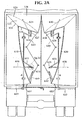
- Figure 2A depicts a rear view of an exemplary embodiment of the present invention, attached to the rear of a trailer box, with the invention in the fully deployed position.
- Figure 2B depicts a rear view of an exemplary embodiment of the present invention, attached to the rear of a trailer box, with the invention in the fully stowed position.
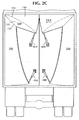
- Figure 2C depicts a rear view of an exemplary embodiment of the present invention, illustrating an embodiment of a tensioning mechanism that can be utilized in this invention.
- Figure 2D depicts an exemplary embodiment of the collar 615.
- Figure 3A depicts a side elevational view of an exemplary embodiment of the present invention, attached to the rear of a trailer box, with the invention in the fully deployed position.
- Figure 3B depicts a side elevational view of an exemplary embodiment of the present invention, attached to the rear of a trailer box, with the invention in the fully stowed position.
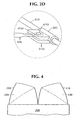
- Figure 4 depicts a top view of an exemplary embodiment of the present invention, attached to the rear of a trailer box, with the invention in the fully deployed position.
- Figures 5A and 5B depict plan views of exemplary embodiments of horizontal fairing surface 120 and vertical fairing surface 110 in unassembled form.
- Figure 6 depicts an exemplary mechanism for the joinder of panel 124 with panel 125.
- FIG. 1 there is shown an exemplary embodiment of this invention, which includes two principal assemblies, a first fairing assembly 100 and a second fairing assembly 200. These assemblies are secured (as explained below) to the rear portion of a vehicle or vehicle element, which as shown in the figures is the rear portion of a truck trailer box 300, although this invention can be utilized to reduce drag in any transport vehicle or means having a relatively blunt rear.
- the rear of trailer box 300 in Figure 1 is a vertical surface, and preferably comprises two doors, as is known in the art, which are hinged to rotate in proximity to the axes defined by vertical rear trailer edges 312 and 314. This hinge arrangement permits the doors to open and close by pivoting approximately about edges 312 and 314.
- Assemblies 100 and 200 are identical, except that assembly 200 is a mirror image of assembly 100.
- assembly 200 is a mirror image of assembly 100.
- the following description will generally refer to the components of assembly 100 only, it being recognized that the description applies equally well to assembly 200.
- Assembly 100 includes two principal components, a vertical fairing surface 110 and a horizontal fairing surface 120.
- surfaces 110 and 120 When folded or stowed, surfaces 110 and 120 are generally planar in geometry, although as described below (and as depicted in Figure 1 ) they each do assume a curvature when deployed.
- the vertical fairing surface 110 and horizontal fairing surface 120 are each semi-rigid in construction.
- a surface or panel is semi-rigid when it is of such thickness and material properties that, when flat, its bending stiffness and strength are low enough to permit the panel to bend elastically, without permanent deformation, to a radius of the same order of magnitude as the panel's width or height, and yet, when so bent elastically, the panel has sufficient resistance to buckling to enable it to resist load as a shell structure. Since the bending is elastic, the surface will re-assume a planar geometry upon ending the application of the external force used to create the bending.
- This semi-rigid construction can be achieved by forming each of the vertical fairing surface 110 and horizontal fairing surface 120 from a sheet of material such as sheet polypropylene.
- Vertical fairing surface 110 includes a terminal portion 111 that is depicted as a linear edge of surface 110, although it is not essential to this invention that portion 111 be linear.
- Vertical fairing surface 110 is secured to the rear of trailer box 300 (in this case at terminal portion 111) in a manner which permits surface 110 to rotate approximately about the axis defined by vertical trailer edge 312.
- the terminal portion 111 of vertical fairing surface 110 is secured to trailer box 300 by any suitable feature or mechanism that will accord it the aforementioned rotational degree of freedom, such as by mechanical hinges.
- any feature or mechanism permitting such a rotational degree of freedom is suitable for use in the present invention, and that such a feature or mechanism need not be necessarily secured to terminal portion 111.
- horizontal fairing surface 120 includes a terminal portion 121 that is depicted as a linear edge of surface 120, although it is not essential to this invention that portion 121 be linear.
- Horizontal fairing surface 120 is secured to the rear of trailer box 300 (in this case at terminal portion 121) in a manner which permits surface 120 to rotate approximately about the axis defined by horizontal trailer edge 313.
- the terminal portion 121 of horizontal fairing surface 120 is secured to trailer box 300 by any suitable mechanism that will accord it the aforementioned rotational degree of freedom, such as by mechanical hinges.
- any mechanism permitting such a rotational degree of freedom is suitable for use in the present invention, and that such a mechanism need not be secured to terminal portion 121.
- horizontal fairing surface 120 has a joint structure 123 spanning horizontal fairing surface 120 from the intersection of terminal portion 121 and curved edge 122 to, in this case, the diagonally opposite corner of horizontal fairing surface 120.
- the purpose of joint structure 123 is to allow the two parts of horizontal fairing surface 120, specifically horizontal center panel 124 and horizontal side panel 125, to fold together when fairing assembly 100 is stowed against the trailer body.
- orientation of joint structure 123 is preferably in accordance with the orientation that will most easily permit panels 124, 125 of horizontal fairing surface 120 to fold together and against vertical fairing surface 110 in a compact manner without significantly stressing or bending the components, or requiring undue force to hold the folded assembly together.
- Joint structure 123 allows rotation of panels 124, 125 relative to each other, while also permitting bending of the joint structure 123 as such rotation proceeds. While depicted as linear, joint structure 123 optionally can be curved, as a means for imparting more shape.
- a joint structure mechanism suitable for joint structure 123 is depicted in Figure 6 .
- one end of an elastomeric member 1123 is clamped between parts 620, 625 of securing member 615, and the other end of elastomeric member 1123 is clamped between parts 635, 640 of securing member 630.
- Securing members 615 and 630 which can be formed of molded polypropylene or other suitable material, are in turn respectively joined to parts 124 and 125 in any suitable manner, such as by rivets, welds, nuts and bolts, or the like.
- Elastomeric member 1123 or securing members 615 and 630 (or all) can be continuous in length, or interrupted, as is preferred.
- joint structure 123 can be a series of interrupted hinges spaced along the length of the intersection of panels 124, 125, as well as other mechanisms providing a similar function.
- vertical fairing surface 110 has a curved edge 112 and horizontal fairing surface 120 has a curved edge 122.
- edges 112 and 122 are joined along their lengths by a joint structure 133 (depicted in Figures 1 and 2A ) that allows rotation of surface 120 relative to surface 110 about the intersection of edges 112, 122, while also permitting bending of the joint structure 133 as such rotation proceeds.
- the joint structure 133 can be as depicted in Figure 6 .
- joint structure 133 can be a series of interrupted hinges along the length of the intersection of curves 112, 122, as well as other mechanisms providing a similar function.
- fairing assembly 100 proceeds as follows, starting from the condition where assembly 100 is stowed against the trailer body. More particularly, in that condition, horizontal fairing surface 120 is stowed against the trailer body, and the upper portion of vertical fairing surface 110 is stowed against horizontal fairing surface 120.
- the two panels 124, 125 are in a folded state, with panel 124 sandwiched between panel 125 and the trailer body, and panel 125 sandwiched between vertical fairing surface 110 and panel 124.
- Deployment commences by simply rotating vertical fairing surface 110 out away from the container body, as a result of which horizontal fairing surface 120 - also starts to deploy. As this operation proceeds, the internal angle between surface 110 and panel 125 starts to open up, which in turn causes the region of surface 120 proximate to curved edge 122 to be urged into a downwardly curved shape, in seeking to conform to the curvature of curved edge 112. Likewise, the region of vertical surface 110 proximate to curved edge 112 is urged into a curved shape, in seeking to conform to the curvature of curved edge 122.
- a force or torque is applied to horizontal fairing surface 120 in a manner causing horizontal fairing surface 120 to elastically buckle outward along the length of joint structure 123, with the result that panels 124, 125 are made locally co-planar in the region of joint structure 123, while the buckling action causes surface 120 to assume a curved shape.
- a force may be applied in the region of the anti-node of the primary buckling mode of horizontal fairing surface 120, in a direction generally normal to the plane of surface 120.
- the result of surface 120 buckling outward is to "lock" joint structure 123 in the open position, until such time as another force is applied to cause structure 123 to buckle back into its original shape, thus freeing up joint structure 123 to rotate.
- Deployment and stowage of the fairing surfaces can be done manually or using deployment/stowage mechanisms.
- a deployment mechanism comprising two torsion bars 610, 620 that are secured to the doors of the trailer box to permit the bars to be rotated by movement of handles 612, 622. This rotational movement causes levers 613, 614, and 623, 624 to swing outward.
- Collars 615, 625 which are respectively positioned in a slip-wise manner over levers 613 and 623, are attached via fasteners to lower arms 616, 626.
- collars 627, 628 are respectively positioned in a slip-wise manner over turned up portions of levers 614, 624, and are attached via fasteners to upper arms 629, 630.
- the lower arm 616 is fastened to vertical fairing 110, as lower arm 626 is fastened to vertical fairing 210.
- upper arm 629 is fastened to horizontal fairing 120, and upper arm 630 is fastened to horizontal fairing 220.
- the collars 615, 625, and 627, 628 are free to rotate as levers 613, 623, and 614, 624 move.
- arms 616, 266, and 629, 630 are fastened so as to be able to rotate about the fastener in a spatial plane passing through the center line of the portion of the lever about which the associated collar rotates.
- Figure 2D shows collar 615 in further detail, and illustrates that collar 615 can move along the length of lever 613 and rotate about lever 613.
- Fastener 6151 is a pin that fastens lower arm 616 between two trunions 6152, 6153 that are part of fastener 615, thereby permitting lever 616 to rotate as described above.
- the rigidity of fairing assemblies 100, 200 can be enhanced by tensioning inward the free edges of vertical fairing surface 110 and horizontal fairing surface 120 during or subsequent to their deployment.
- a tensioning mechanism comprising four tensioning components, pneumatic or hydraulic cylinders 410, 420, 430 and 440, respectively attached to the free edges of horizontal fairing surfaces 120, 220, and vertical fairing surfaces 110, 210.
- the hydraulic cylinders of the tensioning mechanism are actuated after deployment of the fairing assemblies 100, 200 to pull the free edges of the fairing assemblies inward. This further curves horizontal fairing surfaces 120, 220 and vertical fairing surfaces 110,210, and gives them a more aerodynamically effective, drag-reducing shape, in addition to further rigidifying the fairing assembles 100, 200.
- This desirable tensioning can also be obtained by other tensioning mechanism designs, such as cable arrangements.
- tensioning mechanism designs such as cable arrangements.
- FIG 2A there is shown in Figure 2A a set of four cables 641, 642, 643 and 644, which are used to provide the requisite tensioning. These cables 641-644 can be tensioned after deployment of fairing assembles 100, 200.
- the tensioning mechanism can be designed to cause tensioning in a passive manner, such that deployment of the fairing surfaces by itself causes the tensioning mechanism to operate and, in turn, bend the fairing surfaces in an appropriate manner.
- tensioning of cables 641-644 can be accomplished by securing them to rings 651, 652 at an appropriate length. By doing so, the cables 641-644 assume a tensioned state after partial deployment of the fairing surfaces, and further deployment of the fairing surfaces to a fully deployed state causes the fairing surfaces to bend to the appropriate degree.
- a similar passive tensioning function can be achieved by using other suitable tensioning mechanism designs, such as designs employing rods, levers, etc., as the primary elements, as would be evident to a person of ordinary skill in the art.
- Certain tensioning mechanisms can also be used to effect deployment and retraction of the fairing assemblies 100, 200.
- the initial deployment of vertical fairing surfaces 110, 210 and horizontal fairing surfaces 120, 220 can be effected by extending cylinders 430, 440, 410 and 420.
- cylinders 430, 440, 410 and 420 can be partially retracted to pull the free ends of the fairing assemblies inward.
- tensioning mechanism designs can be secured to the typical outward-folding hinged trailer box loading doors, and will not impede use thereof.
- the tensioning mechanism can be secured to a hinged frame that folds against the back of the trailer box during highway operation and against the sides (or one side, depending upon whether the frame is split into two halves) of the trailer box during loading/unloading operations.
Landscapes
- Engineering & Computer Science (AREA)
- Chemical & Material Sciences (AREA)
- Combustion & Propulsion (AREA)
- Transportation (AREA)
- Mechanical Engineering (AREA)
- Body Structure For Vehicles (AREA)
- Chemical And Physical Treatments For Wood And The Like (AREA)
- Aiming, Guidance, Guns With A Light Source, Armor, Camouflage, And Targets (AREA)
Claims (9)
- Fahrzeugelementverkleidungsstruktur (100, 200), umfassend:eine erste halbsteife Fläche (120, 220) mit einem ersten gekrümmten Rand (122), wobei die erste halbsteife Fläche (120, 220) ausgestaltet ist, drehbar an einem Fahrzeugelement (300) befestigt zu werden, um der ersten halbsteifen Fläche (120, 220) zu ermöglichen, eine erste Position benachbart zu dem Fahrzeugelement (300) und eine zweite Position, welche sich von dem Fahrzeugelement (300) erstreckt, anzunehmen, und wobei die erste halbsteife Fläche zwei verbundene Platten (124, 125) umfasst, um der ersten halbsteifen Fläche (120, 220) zu ermöglichen, gefaltet zu sein, wenn sie sich in der ersten Position befindet, und entfaltet zu sein, wenn sie sich in der zweiten Position befindet;eine zweite halbsteife Fläche (110, 210) mit einem zweiten gekrümmten Rand (112), wobei die zweite halbsteife Fläche (110, 210) ausgestaltet ist, drehbar an dem Fahrzeugelement (300) befestigt zu werden, um der zweiten halbsteifen Fläche (110, 210) zu ermöglichen, eine erste Position benachbart zu dem Fahrzeugelement (300) und eine zweite Position, welche sich von dem Fahrzeugelement (300) erstreckt, anzunehmen; undwobei die erste und die zweite halbsteife Fläche (120, 220, 110, 210) an ihren ersten und zweiten gekrümmten Rändern (122, 112) miteinander verbunden sind, um der ersten und der zweiten halbsteifen Fläche (120, 220, 110, 210) zu ermöglichen, näherungsweise zusammengefaltet zu sein, wenn die erste und die zweite halbsteife Fläche (120, 220, 110, 210) benachbart zu dem Fahrzeugelement (300) sind.
- Fahrzeugelementverkleidungsstruktur (100, 200) nach Anspruch 1, ferner umfassend einen Zugmechanismus (410, 420, 430, 440; 641, 642, 643, 644), welcher an der ersten halbsteifen Fläche (120, 220) und der zweiten halbsteifen Fläche (110, 210) befestigt ist und ausgestaltet ist, an dem Fahrzeugelement (300) befestigt zu werden.
- Fahrzeugelementverkleidungsstruktur (100, 200) nach Anspruch 1, ferner umfassend einen Entfaltungs/Verstaumechanismus (610-630).
- Fahrzeugelementverkleidungsstruktur nach Anspruch 1,
wobei die erste halbsteife Fläche (120, 220) einen dritten Rand (121) und einen vierten Rand aufweist, wobei der erste gekrümmte Rand (122) den dritten (121) und vierten Rand verbindet, und
wobei die zweite halbsteife Fläche (110, 210) einen fünften Rand (111) und einen sechsten Rand aufweist, wobei der zweite gekrümmte Rand (112) den fünften (111) und sechsten Rand verbindet. - Fahrzeugelement (300) mit einer Verkleidungsstruktur (100, 200) nach einem der Ansprüche 1-4,
wobei die erste halbsteife Fläche (120, 220) drehbar an dem Fahrzeugelement (300) befestigt ist, um der ersten halbsteifen Fläche (120, 220) zu ermöglichen, eine erste Position benachbart zu dem Fahrzeugelement (300) und eine zweite Position, welche sich von dem Fahrzeugelement (300) erstreckt, anzunehmen, und wobei die zweite halbsteife Fläche (110, 210) drehbar an dem Fahrzeugelement (300) befestigt ist, um der zweiten halbsteifen Fläche (110, 210) zu ermöglichen, eine erste Position benachbart zu dem Fahrzeugelement (300) und eine zweite Position, welche sich von dem Fahrzeugelement (300) erstreckt, anzunehmen. - Fahrzeugelement (300) nach Anspruch 5, ferner umfassend einen Zugmechanismus (410, 420, 430, 440; 641, 642, 643, 644), welcher zwischen der ersten halbsteifen Fläche (120, 220) und dem Fahrzeugelement (300) und zwischen der zweiten halbsteifen Fläche (110, 210) und dem Fahrzeugelement (300) befestigt ist.
- Bausatz für eine Fahrzeugelementverkleidungsstruktur (100, 200), umfassend:eine erste halbsteife Fläche (120, 220) mit einem ersten gekrümmten Rand (122), wobei die erste halbsteife Fläche (120, 220) ausgestaltet ist, drehbar an einem Fahrzeugelement (300) befestigt zu werden, um der ersten halbsteifen Fläche (120, 220) zu ermöglichen, eine erste Position benachbart zu dem Fahrzeugelement (300) und eine zweite Position, welche sich von dem Fahrzeugelement (300) erstreckt, einzunehmen, und wobei die erste halbsteife Fläche (120, 220) zwei verbundene Platten (124, 125) umfasst, um der ersten halbsteifen Fläche (120, 220) zu ermöglichen, gefaltet zu sein, wenn sie sich in der ersten Position befindet, und entfaltet zu sein, wenn sie sich in der zweiten Position befindet;eine zweite halbsteife Fläche (110, 210) mit einem zweiten gekrümmten Rand (112), wobei die zweite halbsteife Fläche (110, 210) ausgestaltet ist, drehbar an dem Fahrzeugelement (300) befestigt zu werden, um der zweiten halbsteifen Fläche (110, 210) zu ermöglichen, eine erste Position benachbart zu dem Fahrzeugelement (300) und eine zweite Position, welche sich von dem Fahrzeugelement (300) erstreckt, einzunehmen; und wobei die erste und die zweite halbsteife Fläche (120, 220, 110, 210) ausgestaltet sind, an ihren ersten und zweiten gekrümmten Rändern (122, 112) miteinander verbunden zu werden, um der ersten und der zweiten halbsteifen Fläche (120, 220, 110, 210) zu ermöglichen, sich näherungsweise zusammenzufalten, wenn die erste und die zweite halbsteife Fläche (120, 220, 110, 210) benachbart zu dem Fahrzeugelement (300) sind.
- Bausatz für eine Fahrzeugelementverkleidungsstruktur (100, 200) nach Anspruch 7, ferner umfassend einen Zugmechanismus (410, 420, 430, 440; 641, 642, 643, 644), welcher ausgestaltet ist, zwischen der ersten halbsteifen Fläche (120, 220) und dem Fahrzeugelement (300) und zwischen der zweiten halbsteifen Fläche (110, 210) und dem Fahrzeugelement (300) befestigt zu werden.
- Bausatz für eine Fahrzeugelementverkleidungsstruktur (100, 200) nach Anspruch 7, ferner umfassend einen Entfaltungs-/Verstaumechanismus (610-630).
Applications Claiming Priority (3)
| Application Number | Priority Date | Filing Date | Title |
|---|---|---|---|
| US10/323,700 US6799791B2 (en) | 2002-12-19 | 2002-12-19 | Deployable vehicle fairing structure |
| US323700 | 2002-12-19 | ||
| PCT/US2003/040772 WO2004056642A2 (en) | 2002-12-19 | 2003-12-19 | Deployable vehicle fairing structure |
Publications (2)
| Publication Number | Publication Date |
|---|---|
| EP1578656A2 EP1578656A2 (de) | 2005-09-28 |
| EP1578656B1 true EP1578656B1 (de) | 2008-11-12 |
Family
ID=32593274
Family Applications (1)
| Application Number | Title | Priority Date | Filing Date |
|---|---|---|---|
| EP03813823A Expired - Lifetime EP1578656B1 (de) | 2002-12-19 | 2003-12-19 | Entfaltbare fahrzeugverkleidungskonstruktion |
Country Status (9)
| Country | Link |
|---|---|
| US (1) | US6799791B2 (de) |
| EP (1) | EP1578656B1 (de) |
| JP (1) | JP2006510538A (de) |
| AT (1) | ATE414003T1 (de) |
| AU (1) | AU2003303202B2 (de) |
| CA (1) | CA2510464C (de) |
| DE (1) | DE60324706D1 (de) |
| ES (1) | ES2318204T3 (de) |
| WO (1) | WO2004056642A2 (de) |
Families Citing this family (110)
| Publication number | Priority date | Publication date | Assignee | Title |
|---|---|---|---|---|
| CN1308178C (zh) * | 2000-12-23 | 2007-04-04 | 宝马公司 | 汽车车身外壳的平坦部分 |
| US6926345B2 (en) * | 2002-09-20 | 2005-08-09 | The Regents Of The University Of California | Apparatus and method for reducing drag of a bluff body in ground effect using counter-rotating vortex pairs |
| US8627738B2 (en) * | 2005-06-29 | 2014-01-14 | Thomas Scott Breidenbach | Linear-curvilinear actuating apparatus with rotating joints |
| US7380868B2 (en) * | 2005-06-29 | 2008-06-03 | Thomas Scott Breidenbach | Aerodynamic drag reducing apparatus |
| US7374230B2 (en) * | 2005-12-01 | 2008-05-20 | Thomas Scott Breidenbach | Aerodynamic drag reducing apparatus |
| US7845708B2 (en) | 2007-06-06 | 2010-12-07 | Adaptive Aerodynamic, Llc | Aerodynamic drag reducing apparatus |
| WO2007007342A2 (en) * | 2005-07-14 | 2007-01-18 | Doron Neuburger | Drag reducing system |
| US7240958B2 (en) * | 2005-07-27 | 2007-07-10 | Joseph Skopic | Apparatus for reducing drag on unpowered vehicles |
| FR2889153B1 (fr) | 2005-08-01 | 2008-10-17 | Fabrice Paille | Dispositif aerodynamique pour les equipements de manutention portes par un vehicule routier de transport de marchandise |
| US7243980B2 (en) * | 2005-08-03 | 2007-07-17 | Philip Vala | Vehicle drag reduction apparatus |
| US7207620B2 (en) * | 2005-08-23 | 2007-04-24 | Cosgrove William E | Aerodynamic drag reducing system with retrofittable, selectively removable frame |
| US7104591B1 (en) * | 2005-10-03 | 2006-09-12 | Sanns Randy A | Windbreaker air drag reduction system |
| US8079634B2 (en) * | 2005-10-26 | 2011-12-20 | Clarkson University | Sealed AFT cavity drag reducer |
| US7618086B2 (en) * | 2005-12-01 | 2009-11-17 | Thomas Scott Breidenbach | Aerodynamic drag reducing apparatus |
| US8007030B2 (en) | 2006-01-30 | 2011-08-30 | Richard Wood | Frame extension device for reducing the aerodynamic drag of ground vehicles |
| US7585015B2 (en) * | 2006-01-30 | 2009-09-08 | Solus Solutions And Technologies, Llc | Frame extension device for reducing the aerodynamic drag of ground vehicles |
| US7497502B2 (en) | 2006-06-19 | 2009-03-03 | Solus Solutions And Technologies, Llc | Mini skirt aerodynamic fairing device for reducing the aerodynamic drag of ground vehicles |
| US7740303B2 (en) | 2006-06-19 | 2010-06-22 | Richard Wood | Mini skirt aerodynamic fairing device for reducing the aerodynamic drag of ground vehicles |
| US20080048468A1 (en) * | 2006-08-23 | 2008-02-28 | Robert Holubar | Air drag reduction apparatus for tractor-trailers |
| US7976096B2 (en) * | 2006-08-23 | 2011-07-12 | Robert Holubar | Air drag reduction apparatus for tractor-trailers |
| CA2662488A1 (en) * | 2006-09-13 | 2008-03-20 | Aerofficient Llc | Vehicle fairing system |
| US7404592B2 (en) * | 2006-09-13 | 2008-07-29 | Aerofficient, Llc | Vehicle fairing system |
| US7604284B2 (en) * | 2006-09-13 | 2009-10-20 | Aerofficient, Llc | Vehicle fairing structure |
| US20080217957A1 (en) * | 2007-03-05 | 2008-09-11 | International Truck Intellectual Property Company, Llc | Aerodynamic forebody shape for van trailer |
| US7837254B2 (en) * | 2007-03-09 | 2010-11-23 | Aeroefficient, LLC | Vehicle fairing structure |
| US8287030B2 (en) * | 2007-04-05 | 2012-10-16 | Airodynamic Trailer Systems, LLC | Drag reducing apparatus for a vehicle |
| US8360509B2 (en) * | 2007-05-17 | 2013-01-29 | Advanced Transit Dynamics, Inc. | Rear-mounted aerodynamic structure for truck cargo bodies |
| US8100461B2 (en) * | 2007-05-17 | 2012-01-24 | Advanced Transit Dynamics, Inc. | Rear-mounted aerodynamic structure for truck cargo bodies |
| AU2013224712B2 (en) * | 2007-05-17 | 2016-05-26 | Advanced Transit Dynamics, Inc. | Rear-mounted aerodynamic structure for truck cargo bodies |
| WO2009018482A1 (en) * | 2007-08-01 | 2009-02-05 | Sinhatech | Deturbilator fuel economy enhancement for trucks |
| US7726724B2 (en) * | 2007-10-10 | 2010-06-01 | Stephen Kohls | Aerodynamic device and method of use |
| US7942466B2 (en) * | 2008-02-21 | 2011-05-17 | Aerofficient Llc | Vehicle side fairing system |
| US7857376B2 (en) | 2008-02-21 | 2010-12-28 | Adaptive Aerodynamic, Llc | Aerodynamic drag reducing apparatus |
| US8408570B2 (en) * | 2008-02-21 | 2013-04-02 | Aerofficient Llc | Vehicle side fairing system |
| US8382194B2 (en) * | 2008-03-21 | 2013-02-26 | Richard M. Wood | Outboard wake stabilization device and method for reducing the aerodynamic drag of ground vehicles |
| US7625034B1 (en) | 2008-04-04 | 2009-12-01 | Fitzgerald James P | Cargo vehicle with drag reduction |
| US8091951B1 (en) | 2008-04-04 | 2012-01-10 | Fitzgerald James P | Cargo vehicle with drag reduction |
| US8100426B2 (en) * | 2008-09-29 | 2012-01-24 | David Kronenberg | Systems for positioning and linking motor vehicles to reduce aerodynamic drag |
| US20100082179A1 (en) | 2008-09-29 | 2010-04-01 | David Kronenberg | Methods for Linking Motor Vehicles to Reduce Aerodynamic Drag and Improve Fuel Economy |
| BRPI0823241A2 (pt) * | 2008-11-06 | 2015-06-16 | Volvo Lastavganar Ab | Dispositivo aerodinâmico para um veículo |
| USD595195S1 (en) * | 2009-02-27 | 2009-06-30 | James P Fitzgerald | Aerodynamic performance enhancing semi-trailer component |
| US7950720B2 (en) * | 2009-03-05 | 2011-05-31 | Joseph Skopic | Apparatus for reducing drag on vehicles with planar rear surfaces |
| US20110115254A1 (en) * | 2009-03-05 | 2011-05-19 | Joseph Skopic | Apparatus for reducing drag on vehicles with planar rear surfaces |
| US7740304B1 (en) * | 2009-03-07 | 2010-06-22 | Thomas James Breu | Umbrella semi-trailer drag reducer |
| CA2948802C (en) * | 2009-04-16 | 2019-06-04 | Wabash National, L.P. | Side skirt and side underride cable system for a trailer |
| WO2011019768A2 (en) * | 2009-08-11 | 2011-02-17 | Draggone Aerodynamics, Inc. | Device for improving a tractor-trailer combination truck aerodynamics at the rear of the trailer |
| US8403401B2 (en) * | 2009-08-24 | 2013-03-26 | Daimler Trucks North America Llc | Adjustable air-deflecting panel for a vehicle |
| US8770650B1 (en) * | 2010-03-10 | 2014-07-08 | Jon Andrew Brosseau | Variable geometry aerodynamic fairing for reducing base drag of tractor trailers |
| CA2707550C (en) | 2010-04-14 | 2012-01-10 | Innovative Trailer Design Technologies Inc. | Side skirt mounting assembly for container chassis |
| EP2529966A1 (de) | 2011-05-28 | 2012-12-05 | De la Torre San José, Rafael | LKW-Anhänger mit aerodynamisch variabler und optimierter Form |
| WO2013043890A1 (en) | 2011-09-20 | 2013-03-28 | Advanced Transit Dynamics, Inc. | Rear-mounted retractable aerodynamic structure for cargo bodies |
| US9440689B1 (en) | 2011-09-20 | 2016-09-13 | Stemco Lp | Aerodynamic structures secured to the underbody of cargo bodies |
| WO2013044216A1 (en) | 2011-09-23 | 2013-03-28 | Aerofab Llc | Vehicle drag reduction assembly |
| WO2013063479A1 (en) * | 2011-10-27 | 2013-05-02 | Advanced Transit Dynamics, Inc. | Rear-mounted aerodynamic structures for cargo bodies |
| US8783758B2 (en) | 2012-03-21 | 2014-07-22 | Wabash National, L.P. | Folding side skirt system for a trailer |
| US8857893B2 (en) | 2012-05-24 | 2014-10-14 | Aerofficient, Llc | Intermodal chassis side fairing system |
| MX357105B (es) | 2012-06-13 | 2018-06-26 | Auto Res Center Llc | Dispositivo de convergencia de estela para un vehículo. |
| WO2013192338A1 (en) * | 2012-06-19 | 2013-12-27 | Aerovolution Corporation | Apparatuses, assemblies, and methods for drag reduction of land vehicles |
| EP2872378A1 (de) | 2012-07-11 | 2015-05-20 | Advanced Transit Dynamics, Inc. | Einziehbare aerodynamische strukturen für frachtkörper und verfahren zur positionssteuerung dafür |
| US9199673B2 (en) | 2012-10-30 | 2015-12-01 | Wabash National, L.P. | Aerodynamic rear drag reduction system for a trailer |
| US10953932B2 (en) | 2012-11-07 | 2021-03-23 | Ekostinger, Inc. | Multicomponent improved vehicle fuel economy system |
| US8985677B2 (en) | 2012-11-07 | 2015-03-24 | StormBlok Systems, Inc. | Vehicle fuel economy system |
| US8672391B1 (en) * | 2012-12-16 | 2014-03-18 | Nathan Ian Cobb | Unobstructive aerodynamic structure for the aft end of cargo trailers |
| DE102013006376A1 (de) | 2013-04-13 | 2014-10-16 | Wabco Gmbh | Heckspoilereinrichtung für ein Fahrzeug |
| US8973974B2 (en) * | 2013-04-30 | 2015-03-10 | Wabash National, L.P. | Aerodynamic rear fairing system for a trailer |
| DE102013008910B4 (de) * | 2013-05-25 | 2022-05-12 | Zf Cv Systems Hannover Gmbh | Heckspoilereinrichtung für ein Fahrzeug und Verfahren zu deren Verstellung |
| US9180919B2 (en) * | 2013-06-18 | 2015-11-10 | Thomas Scott Breidenbach | Aerodynamic drag reducing apparatus |
| WO2014210360A1 (en) | 2013-06-27 | 2014-12-31 | Aerovolution Corporation | Self-deploying apparatuses, assemblies, and methods for drag reduction of land vehicles |
| US20150035312A1 (en) | 2013-07-31 | 2015-02-05 | Ridge Corporation | Device for reducing vehicle aerodynamic resistance |
| US9919750B2 (en) | 2013-08-15 | 2018-03-20 | Wabash National, L.P. | Side skirt system for reducing drag |
| US9283998B2 (en) | 2013-08-27 | 2016-03-15 | Mac Trailer Manufacturing, Inc. | Air fairing for frameless trailer |
| DE102013110363B4 (de) * | 2013-09-19 | 2025-05-28 | Dr. Ing. H.C. F. Porsche Aktiengesellschaft | Luftleitvorrichtung für ein Fahrzeug |
| NL2011492C2 (en) | 2013-09-25 | 2015-03-30 | Wabco Europ Bvba | Drag reducing device. |
| US9522706B1 (en) * | 2013-10-18 | 2016-12-20 | Thomas Scott Breidenbach | Aerodynamic drag reducing apparatus |
| DE102014014215A1 (de) | 2014-02-21 | 2015-08-27 | Wabco Europe Bvba | Heckspoilereinrichtung für ein Fahrzeug |
| US9409610B2 (en) | 2014-03-11 | 2016-08-09 | Wabash National, L.P. | Side skirt system for a trailer |
| US9409609B2 (en) | 2014-03-24 | 2016-08-09 | Auto Research Center, Llc | Wake convergence device for a pick-up truck |
| DE102014005374A1 (de) * | 2014-04-11 | 2015-10-15 | Wabco Europe Bvba | Heckspoilereinrichtung für ein Fahrzeug |
| US9616944B2 (en) | 2014-05-15 | 2017-04-11 | Wabash National, L.P. | Aerodynamic rear drag reduction system for a trailer |
| DE102014113780B4 (de) | 2014-09-23 | 2022-06-30 | Zf Cv Systems Europe Bv | Heckspoilereinrichtung für ein Fahrzeug |
| US9688320B2 (en) | 2014-10-29 | 2017-06-27 | Wabash National, L.P. | Side skirt system for a trailer |
| MX368079B (es) | 2015-02-16 | 2019-09-18 | Wabash National Lp | Sistema de reduccion de resistencia aerodinamica posterior para un remolque. |
| MX376788B (es) * | 2015-04-29 | 2025-03-07 | Wabash National Lp | Sistema aerodinámico de reducción de resistencia trasera para un remolque. |
| US9776674B2 (en) | 2015-04-29 | 2017-10-03 | Wabash National, L.P. | Aerodynamic rear drag reduction system for a trailer |
| CA2901497A1 (en) | 2015-05-22 | 2016-11-22 | Wabash National, L.P. | Nose gap reducers for trailers |
| DE102015115887A1 (de) * | 2015-09-21 | 2017-03-23 | Wihag Fahrzeugbausysteme Gmbh | Vorrichtung zur Verbesserung der Aerodynamik an einem Fahrzeug |
| DE102015012495A1 (de) | 2015-09-24 | 2017-03-30 | Wabco Europe Bvba | Heckspoilereinrichtung für ein Fahrzeug |
| US9555841B1 (en) * | 2015-10-26 | 2017-01-31 | Vanguard National Trailer Corporation | Retractable rear fairing |
| US12005969B2 (en) | 2016-04-07 | 2024-06-11 | Fleetaero, Llc | Vehicle aerodynamic improvement apparatus and system |
| US9650086B1 (en) | 2016-09-20 | 2017-05-16 | Raimund Pfaff | Drag reduction apparatus for a trailer |
| US10343731B2 (en) | 2016-09-30 | 2019-07-09 | Wabash National, L.P. | Skirt system mount bracket assembly |
| US10124840B2 (en) * | 2016-10-20 | 2018-11-13 | Toyota Motor Engineering & Manufacturing North America, Inc. | Deployable vehicle air drag reduction mechanism and system |
| US10137945B2 (en) | 2016-11-30 | 2018-11-27 | Xstream Trucking Inc. | Deployable fairing for use with vehicles |
| BR112019011027A2 (pt) * | 2016-11-30 | 2019-10-08 | Xstream Trucking Inc | carenagem expansível para uso em veículos |
| DE102017003191A1 (de) | 2017-04-01 | 2018-10-04 | Wabco Europe Bvba | Heckspoilereinrichtung für ein Nutzfahrzeug |
| US10549797B2 (en) | 2017-04-20 | 2020-02-04 | Wabash National, L.P. | Side underride guard |
| US10946824B2 (en) | 2017-09-13 | 2021-03-16 | Wabash National, L.P. | Side underride guard |
| US10836444B2 (en) * | 2017-10-30 | 2020-11-17 | University Of Maryland, Baltimore County | Rear body structure for varying the shape of commercial trailers and trucks |
| CN107878579B (zh) * | 2017-11-17 | 2020-08-21 | 中国重汽集团济南动力有限公司 | 一种应用于厢式挂车的空气导流装置 |
| CA3028080A1 (en) * | 2017-12-20 | 2019-06-20 | Mathieu Boivin | Automatically actuated rear air drag reducing system and method of use thereof |
| WO2019147809A1 (en) * | 2018-01-24 | 2019-08-01 | Ekostinger, Inc. | Aerodynamic door assembly |
| US10940817B2 (en) | 2018-02-21 | 2021-03-09 | Wabash National, L.P. | Side underride guard |
| US11396334B2 (en) | 2019-03-06 | 2022-07-26 | Trucklabs, Inc. | Deployable fairing system for use with vehicles |
| US11427267B2 (en) | 2019-03-06 | 2022-08-30 | Trucklabs, Inc. | Deployable fairing system for use with vehicles |
| US11242098B2 (en) | 2019-07-26 | 2022-02-08 | Waymo Llc | Efficient autonomous trucks |
| EP4096991A4 (de) * | 2020-03-23 | 2024-03-06 | Timothy Sean Christopher Martin | Vorrichtung und verfahren zur verminderung des widerstandes von sich bewegenden fahrzeugen |
| WO2021226143A1 (en) | 2020-05-04 | 2021-11-11 | Xstream Trucking Inc. | Aerodynamic system for vehicles and methods for operating the same |
| WO2022182427A1 (en) * | 2021-02-23 | 2022-09-01 | Barry Andersen | Apparatus and method for a skirt assembly |
| RU208288U1 (ru) * | 2021-04-27 | 2021-12-13 | Публичное акционерное общество "КАМАЗ" | Аэродинамический полуприцеп транспортного средства |
| CN113401231A (zh) * | 2021-06-11 | 2021-09-17 | 东风柳州汽车有限公司 | 一种导流装置 |
Family Cites Families (47)
| Publication number | Priority date | Publication date | Assignee | Title |
|---|---|---|---|---|
| US121539A (en) * | 1871-12-05 | Improvement in cars for elevated railways | ||
| US2737411A (en) | 1952-08-21 | 1956-03-06 | Ralph B Potter | Inflatable streamlining apparatus for vehicle bodies |
| US2982290A (en) | 1958-01-08 | 1961-05-02 | Hunziker Walter Rudolf | Portable prefabricated shelter |
| US3206100A (en) | 1963-01-07 | 1965-09-14 | Wenger Harry | Packaging box |
| US3371453A (en) | 1964-08-03 | 1968-03-05 | Dehavilland Aircraft Canada | Cassette stem device |
| US3534514A (en) | 1968-12-13 | 1970-10-20 | Sunbird Ind Inc | Shelter using semi-rigid flexed walls |
| US3533202A (en) | 1968-12-13 | 1970-10-13 | Sunbird Ind Inc | Modular shelter or building |
| US3657753A (en) | 1970-09-29 | 1972-04-25 | Leo J Le Blanc Sr | Folding inflatable surfboard |
| US3721027A (en) | 1971-06-22 | 1973-03-20 | Shen & Slavsky Inc | New style picture frame panel |
| FR2145032A5 (de) | 1971-07-07 | 1973-02-16 | Torrix Sa Ets | |
| US3774309A (en) | 1972-06-19 | 1973-11-27 | N Leopoldi | Steel measuring tape holder |
| US4145850A (en) | 1973-09-17 | 1979-03-27 | Runyon John F | Folding modular building structure |
| US4036519A (en) | 1974-08-23 | 1977-07-19 | Aerospan Corporation | Streamlining apparatus for articulated road vehicle |
| US4006932A (en) | 1975-07-21 | 1977-02-08 | The United States Of America As Represented By The Secretary Of The Department Of Transportation | Inflatable drag reducer for land vehicles |
| US4030779A (en) | 1976-03-18 | 1977-06-21 | Johnson David W | Inflatable streamlining structure for vehicles |
| US4088362A (en) | 1976-09-16 | 1978-05-09 | Mollura Carlos A | Inflatable aerodynamic nose cone |
| US4142755A (en) | 1977-08-12 | 1979-03-06 | Keedy Edgar L | Vehicle drag reducer |
| US4153288A (en) | 1977-09-26 | 1979-05-08 | Donna M. Mueller | Folding air deflector |
| US4257641A (en) * | 1979-05-25 | 1981-03-24 | Keedy Edgar L | Vehicle drag reducer |
| US4419994A (en) | 1980-07-03 | 1983-12-13 | Racal Safety Limited | Respirators |
| US4425929A (en) | 1981-03-26 | 1984-01-17 | Von Mosshaim Horst E | Collapsible structure |
| US4818015A (en) | 1981-11-09 | 1989-04-04 | Scanlon Barry F | Vehicular airfoils |
| US4451074A (en) | 1981-11-09 | 1984-05-29 | Barry Scanlon | Vehicular airfoils |
| US4458936A (en) | 1981-12-23 | 1984-07-10 | Mulholland Frank J | Drag reducing fairing for trucks, trailers and cargo containers |
| US4601508A (en) | 1984-06-18 | 1986-07-22 | Kerian Paul D | Streamlining appendage for vehicles |
| US4702509A (en) | 1986-05-27 | 1987-10-27 | Elliott Sr Morris C | Long-haul vehicle streamline apparatus |
| US4688841A (en) | 1986-06-10 | 1987-08-25 | Moore Mark A | Drag reduction device for tractor-trailers |
| US4741569A (en) | 1987-03-04 | 1988-05-03 | Sutphen Paul F | Inflatable drag reducer for land transport vehicles |
| JPS63301186A (ja) * | 1987-05-26 | 1988-12-08 | ラフリス ゼイン | 運輸手段 |
| US4978162A (en) | 1989-11-29 | 1990-12-18 | Labbe Francois P | Drag reducer for rear end of vehicle |
| US5058945A (en) | 1990-06-08 | 1991-10-22 | Elliott Sr Morris C | Long-haul vehicle streamline apparatus |
| DE4021337A1 (de) | 1990-07-04 | 1992-01-09 | Anton Dipl Ing Dr Lechner | Vorrichtung zur reduzierung des stroemungswiderstandes eines nutzfahrzeuges |
| SE468565B (sv) | 1990-09-18 | 1993-02-08 | Christer Zarelius | Bandformat boejbart organ |
| US5240306A (en) | 1992-08-05 | 1993-08-31 | Flemming George M | Aerodynamic drag reduction fairing |
| US5498059A (en) | 1994-09-28 | 1996-03-12 | Switlik; Stanley | Apparatus for reducing drag |
| GB9517500D0 (en) | 1995-08-25 | 1995-10-25 | J T Inglis & Sons Limited | Shelter structures |
| US5685597A (en) | 1995-11-27 | 1997-11-11 | Reid; James Charles | Vehicle wind deflector |
| US5947548A (en) | 1996-07-29 | 1999-09-07 | Carper; Herbert J. | Aerodynamic drag reducing geometry for land-based vehicles |
| US6126239A (en) | 1997-04-14 | 2000-10-03 | Chameleon Studio, Inc. | Ready to assemble furniture construction including frameless self-supporting panel members |
| US5823610A (en) | 1997-10-22 | 1998-10-20 | James C. Ryan | Drag reducing apparatus for a vehicle |
| DE19804435C2 (de) | 1998-02-05 | 2000-03-16 | Merz Sauter Zimmermann Gmbh | Entfaltbare Dachkonstruktion |
| US6092861A (en) | 1999-07-26 | 2000-07-25 | Whelan; William | Air drag reduction unit for vehicles |
| US6309010B1 (en) | 1999-09-29 | 2001-10-30 | W. David Whitten | Collapsible streamlined tail for trucks and trailers |
| GB0002519D0 (en) | 2000-02-03 | 2000-03-29 | Univ Dundee | Cantilever support and erectable structures |
| US6428084B1 (en) * | 2001-04-24 | 2002-08-06 | Richard M. Liss | Fuel-efficient tractor-trailer system |
| US6467833B1 (en) | 2001-09-27 | 2002-10-22 | R. H. Travers Company | Drag reducer |
| US6485087B1 (en) * | 2001-11-16 | 2002-11-26 | Maka Innovation Technologique Inc. | Air drag reducing apparatus |
-
2002
- 2002-12-19 US US10/323,700 patent/US6799791B2/en not_active Expired - Lifetime
-
2003
- 2003-12-19 ES ES03813823T patent/ES2318204T3/es not_active Expired - Lifetime
- 2003-12-19 JP JP2004562351A patent/JP2006510538A/ja active Pending
- 2003-12-19 AT AT03813823T patent/ATE414003T1/de not_active IP Right Cessation
- 2003-12-19 CA CA2510464A patent/CA2510464C/en not_active Expired - Fee Related
- 2003-12-19 WO PCT/US2003/040772 patent/WO2004056642A2/en not_active Ceased
- 2003-12-19 EP EP03813823A patent/EP1578656B1/de not_active Expired - Lifetime
- 2003-12-19 DE DE60324706T patent/DE60324706D1/de not_active Expired - Lifetime
- 2003-12-19 AU AU2003303202A patent/AU2003303202B2/en not_active Ceased
Also Published As
| Publication number | Publication date |
|---|---|
| WO2004056642A3 (en) | 2004-08-05 |
| AU2003303202A1 (en) | 2004-07-14 |
| WO2004056642A2 (en) | 2004-07-08 |
| ATE414003T1 (de) | 2008-11-15 |
| AU2003303202B2 (en) | 2009-11-19 |
| CA2510464C (en) | 2010-07-27 |
| US20040119319A1 (en) | 2004-06-24 |
| EP1578656A2 (de) | 2005-09-28 |
| ES2318204T3 (es) | 2009-05-01 |
| US6799791B2 (en) | 2004-10-05 |
| DE60324706D1 (de) | 2008-12-24 |
| JP2006510538A (ja) | 2006-03-30 |
| CA2510464A1 (en) | 2004-07-08 |
Similar Documents
| Publication | Publication Date | Title |
|---|---|---|
| EP1578656B1 (de) | Entfaltbare fahrzeugverkleidungskonstruktion | |
| US9457847B2 (en) | Rear-mounted aerodynamic structures for cargo bodies | |
| US12384470B2 (en) | Truck with a retractable cover | |
| US7404592B2 (en) | Vehicle fairing system | |
| US8641126B2 (en) | Sealed aft cavity drag reducer | |
| US4236745A (en) | Retractable streamlining device for vehicles | |
| US6286894B1 (en) | Reduced-drag trailer | |
| US10023249B2 (en) | Aerodynamic drag reducing apparatus | |
| US6915611B2 (en) | Deployable structure | |
| CN105579332B (zh) | 减阻装置 | |
| US9834262B2 (en) | Aerodynamic rear drag reduction system for a trailer | |
| JPH01182120A (ja) | 自動車の後部開閉体構造 | |
| WO2008033727A2 (en) | Vehicle fairing system | |
| JPH036501Y2 (de) |
Legal Events
| Date | Code | Title | Description |
|---|---|---|---|
| PUAI | Public reference made under article 153(3) epc to a published international application that has entered the european phase |
Free format text: ORIGINAL CODE: 0009012 |
|
| 17P | Request for examination filed |
Effective date: 20050708 |
|
| AK | Designated contracting states |
Kind code of ref document: A2 Designated state(s): AT BE BG CH CY CZ DE DK EE ES FI FR GB GR HU IE IT LI LU MC NL PT RO SE SI SK TR |
|
| AX | Request for extension of the european patent |
Extension state: AL LT LV MK |
|
| DAX | Request for extension of the european patent (deleted) | ||
| REG | Reference to a national code |
Ref country code: HK Ref legal event code: DE Ref document number: 1082237 Country of ref document: HK |
|
| RAP1 | Party data changed (applicant data changed or rights of an application transferred) |
Owner name: AEROFFICIENT, LLC |
|
| 17Q | First examination report despatched |
Effective date: 20071112 |
|
| GRAP | Despatch of communication of intention to grant a patent |
Free format text: ORIGINAL CODE: EPIDOSNIGR1 |
|
| GRAS | Grant fee paid |
Free format text: ORIGINAL CODE: EPIDOSNIGR3 |
|
| GRAA | (expected) grant |
Free format text: ORIGINAL CODE: 0009210 |
|
| AK | Designated contracting states |
Kind code of ref document: B1 Designated state(s): AT BE BG CH CY CZ DE DK EE ES FI FR GB GR HU IE IT LI LU MC NL PT RO SE SI SK TR |
|
| REG | Reference to a national code |
Ref country code: GB Ref legal event code: FG4D |
|
| REG | Reference to a national code |
Ref country code: CH Ref legal event code: EP |
|
| REG | Reference to a national code |
Ref country code: IE Ref legal event code: FG4D |
|
| REF | Corresponds to: |
Ref document number: 60324706 Country of ref document: DE Date of ref document: 20081224 Kind code of ref document: P |
|
| PG25 | Lapsed in a contracting state [announced via postgrant information from national office to epo] |
Ref country code: AT Free format text: LAPSE BECAUSE OF FAILURE TO SUBMIT A TRANSLATION OF THE DESCRIPTION OR TO PAY THE FEE WITHIN THE PRESCRIBED TIME-LIMIT Effective date: 20081112 |
|
| REG | Reference to a national code |
Ref country code: ES Ref legal event code: FG2A Ref document number: 2318204 Country of ref document: ES Kind code of ref document: T3 |
|
| PG25 | Lapsed in a contracting state [announced via postgrant information from national office to epo] |
Ref country code: SI Free format text: LAPSE BECAUSE OF FAILURE TO SUBMIT A TRANSLATION OF THE DESCRIPTION OR TO PAY THE FEE WITHIN THE PRESCRIBED TIME-LIMIT Effective date: 20081112 Ref country code: FI Free format text: LAPSE BECAUSE OF FAILURE TO SUBMIT A TRANSLATION OF THE DESCRIPTION OR TO PAY THE FEE WITHIN THE PRESCRIBED TIME-LIMIT Effective date: 20081112 |
|
| PG25 | Lapsed in a contracting state [announced via postgrant information from national office to epo] |
Ref country code: MC Free format text: LAPSE BECAUSE OF NON-PAYMENT OF DUE FEES Effective date: 20081231 Ref country code: EE Free format text: LAPSE BECAUSE OF FAILURE TO SUBMIT A TRANSLATION OF THE DESCRIPTION OR TO PAY THE FEE WITHIN THE PRESCRIBED TIME-LIMIT Effective date: 20081112 Ref country code: BG Free format text: LAPSE BECAUSE OF FAILURE TO SUBMIT A TRANSLATION OF THE DESCRIPTION OR TO PAY THE FEE WITHIN THE PRESCRIBED TIME-LIMIT Effective date: 20090212 Ref country code: DK Free format text: LAPSE BECAUSE OF FAILURE TO SUBMIT A TRANSLATION OF THE DESCRIPTION OR TO PAY THE FEE WITHIN THE PRESCRIBED TIME-LIMIT Effective date: 20081112 Ref country code: BE Free format text: LAPSE BECAUSE OF FAILURE TO SUBMIT A TRANSLATION OF THE DESCRIPTION OR TO PAY THE FEE WITHIN THE PRESCRIBED TIME-LIMIT Effective date: 20081112 Ref country code: RO Free format text: LAPSE BECAUSE OF FAILURE TO SUBMIT A TRANSLATION OF THE DESCRIPTION OR TO PAY THE FEE WITHIN THE PRESCRIBED TIME-LIMIT Effective date: 20081112 |
|
| REG | Reference to a national code |
Ref country code: CH Ref legal event code: PL |
|
| PG25 | Lapsed in a contracting state [announced via postgrant information from national office to epo] |
Ref country code: SE Free format text: LAPSE BECAUSE OF FAILURE TO SUBMIT A TRANSLATION OF THE DESCRIPTION OR TO PAY THE FEE WITHIN THE PRESCRIBED TIME-LIMIT Effective date: 20090212 Ref country code: CZ Free format text: LAPSE BECAUSE OF FAILURE TO SUBMIT A TRANSLATION OF THE DESCRIPTION OR TO PAY THE FEE WITHIN THE PRESCRIBED TIME-LIMIT Effective date: 20081112 Ref country code: PT Free format text: LAPSE BECAUSE OF FAILURE TO SUBMIT A TRANSLATION OF THE DESCRIPTION OR TO PAY THE FEE WITHIN THE PRESCRIBED TIME-LIMIT Effective date: 20090413 |
|
| PLBE | No opposition filed within time limit |
Free format text: ORIGINAL CODE: 0009261 |
|
| STAA | Information on the status of an ep patent application or granted ep patent |
Free format text: STATUS: NO OPPOSITION FILED WITHIN TIME LIMIT |
|
| PG25 | Lapsed in a contracting state [announced via postgrant information from national office to epo] |
Ref country code: SK Free format text: LAPSE BECAUSE OF FAILURE TO SUBMIT A TRANSLATION OF THE DESCRIPTION OR TO PAY THE FEE WITHIN THE PRESCRIBED TIME-LIMIT Effective date: 20081112 |
|
| 26N | No opposition filed |
Effective date: 20090813 |
|
| PG25 | Lapsed in a contracting state [announced via postgrant information from national office to epo] |
Ref country code: LI Free format text: LAPSE BECAUSE OF NON-PAYMENT OF DUE FEES Effective date: 20081231 Ref country code: CH Free format text: LAPSE BECAUSE OF NON-PAYMENT OF DUE FEES Effective date: 20081231 |
|
| PG25 | Lapsed in a contracting state [announced via postgrant information from national office to epo] |
Ref country code: LU Free format text: LAPSE BECAUSE OF NON-PAYMENT OF DUE FEES Effective date: 20081219 Ref country code: HU Free format text: LAPSE BECAUSE OF FAILURE TO SUBMIT A TRANSLATION OF THE DESCRIPTION OR TO PAY THE FEE WITHIN THE PRESCRIBED TIME-LIMIT Effective date: 20090513 Ref country code: CY Free format text: LAPSE BECAUSE OF FAILURE TO SUBMIT A TRANSLATION OF THE DESCRIPTION OR TO PAY THE FEE WITHIN THE PRESCRIBED TIME-LIMIT Effective date: 20081112 |
|
| PG25 | Lapsed in a contracting state [announced via postgrant information from national office to epo] |
Ref country code: TR Free format text: LAPSE BECAUSE OF FAILURE TO SUBMIT A TRANSLATION OF THE DESCRIPTION OR TO PAY THE FEE WITHIN THE PRESCRIBED TIME-LIMIT Effective date: 20081112 |
|
| PG25 | Lapsed in a contracting state [announced via postgrant information from national office to epo] |
Ref country code: GR Free format text: LAPSE BECAUSE OF FAILURE TO SUBMIT A TRANSLATION OF THE DESCRIPTION OR TO PAY THE FEE WITHIN THE PRESCRIBED TIME-LIMIT Effective date: 20090213 |
|
| PGFP | Annual fee paid to national office [announced via postgrant information from national office to epo] |
Ref country code: IE Payment date: 20101214 Year of fee payment: 8 |
|
| PGFP | Annual fee paid to national office [announced via postgrant information from national office to epo] |
Ref country code: IT Payment date: 20101224 Year of fee payment: 8 |
|
| REG | Reference to a national code |
Ref country code: HK Ref legal event code: WD Ref document number: 1082237 Country of ref document: HK |
|
| REG | Reference to a national code |
Ref country code: IE Ref legal event code: MM4A |
|
| PG25 | Lapsed in a contracting state [announced via postgrant information from national office to epo] |
Ref country code: IE Free format text: LAPSE BECAUSE OF NON-PAYMENT OF DUE FEES Effective date: 20111219 |
|
| PG25 | Lapsed in a contracting state [announced via postgrant information from national office to epo] |
Ref country code: IT Free format text: LAPSE BECAUSE OF NON-PAYMENT OF DUE FEES Effective date: 20111219 |
|
| PGFP | Annual fee paid to national office [announced via postgrant information from national office to epo] |
Ref country code: GB Payment date: 20131218 Year of fee payment: 11 |
|
| PGFP | Annual fee paid to national office [announced via postgrant information from national office to epo] |
Ref country code: ES Payment date: 20131211 Year of fee payment: 11 Ref country code: NL Payment date: 20131210 Year of fee payment: 12 |
|
| PGFP | Annual fee paid to national office [announced via postgrant information from national office to epo] |
Ref country code: DE Payment date: 20141219 Year of fee payment: 12 |
|
| PGFP | Annual fee paid to national office [announced via postgrant information from national office to epo] |
Ref country code: FR Payment date: 20141223 Year of fee payment: 12 |
|
| REG | Reference to a national code |
Ref country code: NL Ref legal event code: V1 Effective date: 20150701 |
|
| REG | Reference to a national code |
Ref country code: NL Ref legal event code: V1 Effective date: 20150701 |
|
| GBPC | Gb: european patent ceased through non-payment of renewal fee |
Effective date: 20141219 |
|
| PG25 | Lapsed in a contracting state [announced via postgrant information from national office to epo] |
Ref country code: NL Free format text: LAPSE BECAUSE OF NON-PAYMENT OF DUE FEES Effective date: 20150701 |
|
| PG25 | Lapsed in a contracting state [announced via postgrant information from national office to epo] |
Ref country code: GB Free format text: LAPSE BECAUSE OF NON-PAYMENT OF DUE FEES Effective date: 20141219 |
|
| REG | Reference to a national code |
Ref country code: ES Ref legal event code: FD2A Effective date: 20160126 |
|
| PG25 | Lapsed in a contracting state [announced via postgrant information from national office to epo] |
Ref country code: ES Free format text: LAPSE BECAUSE OF NON-PAYMENT OF DUE FEES Effective date: 20141220 |
|
| REG | Reference to a national code |
Ref country code: DE Ref legal event code: R119 Ref document number: 60324706 Country of ref document: DE |
|
| REG | Reference to a national code |
Ref country code: FR Ref legal event code: ST Effective date: 20160831 |
|
| PG25 | Lapsed in a contracting state [announced via postgrant information from national office to epo] |
Ref country code: DE Free format text: LAPSE BECAUSE OF NON-PAYMENT OF DUE FEES Effective date: 20160701 |
|
| PG25 | Lapsed in a contracting state [announced via postgrant information from national office to epo] |
Ref country code: FR Free format text: LAPSE BECAUSE OF NON-PAYMENT OF DUE FEES Effective date: 20151231 |