EP1578639B1 - Clothes hanger with a headrest - Google Patents
Clothes hanger with a headrest Download PDFInfo
- Publication number
- EP1578639B1 EP1578639B1 EP03782299A EP03782299A EP1578639B1 EP 1578639 B1 EP1578639 B1 EP 1578639B1 EP 03782299 A EP03782299 A EP 03782299A EP 03782299 A EP03782299 A EP 03782299A EP 1578639 B1 EP1578639 B1 EP 1578639B1
- Authority
- EP
- European Patent Office
- Prior art keywords
- hanger
- use position
- headrest
- shaped
- insert body
- Prior art date
- Legal status (The legal status is an assumption and is not a legal conclusion. Google has not performed a legal analysis and makes no representation as to the accuracy of the status listed.)
- Expired - Lifetime
Links
- 230000005540 biological transmission Effects 0.000 claims description 17
- 238000006073 displacement reaction Methods 0.000 claims description 5
- 230000000717 retained effect Effects 0.000 claims 2
- 230000037431 insertion Effects 0.000 claims 1
- 238000003780 insertion Methods 0.000 claims 1
- 238000009434 installation Methods 0.000 description 13
- 208000027418 Wounds and injury Diseases 0.000 description 4
- 230000006378 damage Effects 0.000 description 4
- 208000014674 injury Diseases 0.000 description 4
- 230000010354 integration Effects 0.000 description 2
- 239000000725 suspension Substances 0.000 description 2
- 238000010276 construction Methods 0.000 description 1
- 230000001419 dependent effect Effects 0.000 description 1
- 230000000763 evoking effect Effects 0.000 description 1
- 239000004744 fabric Substances 0.000 description 1
- 230000001771 impaired effect Effects 0.000 description 1
- 239000012815 thermoplastic material Substances 0.000 description 1
Images


Classifications
-
- B—PERFORMING OPERATIONS; TRANSPORTING
- B60—VEHICLES IN GENERAL
- B60R—VEHICLES, VEHICLE FITTINGS, OR VEHICLE PARTS, NOT OTHERWISE PROVIDED FOR
- B60R7/00—Stowing or holding appliances inside vehicle primarily intended for personal property smaller than suit-cases, e.g. travelling articles, or maps
- B60R7/04—Stowing or holding appliances inside vehicle primarily intended for personal property smaller than suit-cases, e.g. travelling articles, or maps in driver or passenger space, e.g. using racks
- B60R7/043—Stowing or holding appliances inside vehicle primarily intended for personal property smaller than suit-cases, e.g. travelling articles, or maps in driver or passenger space, e.g. using racks mounted on or under a seat
-
- B—PERFORMING OPERATIONS; TRANSPORTING
- B60—VEHICLES IN GENERAL
- B60N—SEATS SPECIALLY ADAPTED FOR VEHICLES; VEHICLE PASSENGER ACCOMMODATION NOT OTHERWISE PROVIDED FOR
- B60N2/00—Seats specially adapted for vehicles; Arrangement or mounting of seats in vehicles
- B60N2/64—Back-rests or cushions
-
- B—PERFORMING OPERATIONS; TRANSPORTING
- B60—VEHICLES IN GENERAL
- B60N—SEATS SPECIALLY ADAPTED FOR VEHICLES; VEHICLE PASSENGER ACCOMMODATION NOT OTHERWISE PROVIDED FOR
- B60N2/00—Seats specially adapted for vehicles; Arrangement or mounting of seats in vehicles
- B60N2/80—Head-rests
- B60N2/806—Head-rests movable or adjustable
- B60N2/809—Head-rests movable or adjustable vertically slidable
-
- B—PERFORMING OPERATIONS; TRANSPORTING
- B60—VEHICLES IN GENERAL
- B60N—SEATS SPECIALLY ADAPTED FOR VEHICLES; VEHICLE PASSENGER ACCOMMODATION NOT OTHERWISE PROVIDED FOR
- B60N2/00—Seats specially adapted for vehicles; Arrangement or mounting of seats in vehicles
- B60N2/80—Head-rests
- B60N2/879—Head-rests with additional features not related to head-rest positioning, e.g. heating or cooling devices or loudspeakers
-
- B—PERFORMING OPERATIONS; TRANSPORTING
- B60—VEHICLES IN GENERAL
- B60R—VEHICLES, VEHICLE FITTINGS, OR VEHICLE PARTS, NOT OTHERWISE PROVIDED FOR
- B60R7/00—Stowing or holding appliances inside vehicle primarily intended for personal property smaller than suit-cases, e.g. travelling articles, or maps
- B60R7/08—Disposition of racks, clips, holders, containers or the like for supporting specific articles
- B60R7/10—Disposition of racks, clips, holders, containers or the like for supporting specific articles for supporting hats, clothes or clothes hangers
Definitions
- the invention relates to a device for suspending objects, in particular garments in a motor vehicle, with the features mentioned in the preamble of claim 1.
- the EP 0 753 427 A2 describes a handle, which has at least one mounted bracket part whose position is variable by means of simple handles between a functional position and a non-functional position.
- the handle is firmly connected to a base part.
- a headrest or a backrest in a motor vehicle come into question.
- the disadvantage here is that the integration in the handle in both Functional position and in non-functional position in case of accidents can lead to injury. Since mostly lateral bracket elements are guided out of the handle, it is also not to be expected that the impact of an occupant leads to a movement of the device in the storage position or non-functional position. Furthermore, such a device lacks any possibility of height adjustment.
- Laid-open specification DE-A-38 01 625 also describes a holder with the same already to the publication EP-A-0 753 427 mentioned disadvantages.
- a holder for clothes in cars is specified, which is sunk when not in use in a recess of a receiving body in which it is articulated, and from which it can be swung out into a position of use in front of the receiving body.
- the holder is similar to a hanger formed and includes two fixed to the end of the recess and adoptedschwenkbare from this support arms, at the end of each a hingedly movable bail arm connects, which is in an extended position with the holding arms in the recesses when not in use, and in the position of use at a distance and approximately parallel to this is pivotable in front of the receiving body.
- this solution does not come in the non-use position without visible elements, so that on the one hand the design is impaired and on the other already in the non-use position there is a risk of injury to the flush with the backrest edge. There is also the risk of injury after extension of the bracket, since a device yielding by a horizontal force can not be expected in this construction either.
- the WO-A-97 / 03,864 ( Figures 4 and 5) has become known, which comprises a device for hanging garments, especially in vehicles, with a receiving housing for installation in a mounting body, such as backrests of seats, headrests or the like, and a, in the Receiving housing in an inner end position recordable holder describes, which is displaceable from this inner end position into an arranged substantially outside of the receiving housing outer end position, in which the holder allows the hanging of garments.
- the WO-A-97 / 03,864 is made of several parts holder in response to the displacement of a, an interior of the receiving housing of the headrest covering, front wall formed.
- the invention therefore has the object of providing a motor vehicle of the type assumed to be known in such a way that a device for hanging objects, in particular clothes, in this motor vehicle is possible without that the design of a motor vehicle seat in the non-use position suggests this device. Furthermore, it is the task to make the device as flexible as possible adjustable, and to arrange them so that in the event of a crash, a largely return of the device from the use position is made possible in the non-use position.
- the bow-shaped element is completely integrated in its non-use position in the mounting body and not visible, especially from the perspective of a designer, this option is particularly advantageous, since surfaces can be designed free of devices on the respective cover elements.
- the bow-shaped element is practically manageable due to its integration and is always available. Depending on the version, there is also the possibility of height adjustment.
- the bow-shaped element adaptable to the respective user.
- the bow-shaped element is not only an auxiliary device, but can be considered and used as a full hanger.
- a first cover in a designated first space, forms a first contour of a part of the mounting body.
- This mounting body is, for example, a headrest, which is fastened by means of headrest mounts to the backrest of the motor vehicle seat.
- the first cover is rotatably mounted on a first axis and thus allows the headrest in the cover member having the part of the mounting body can be opened and closed.
- a rod On the side facing the headrest side of the first cover according to the invention a rod, transmission elements, at least a first and Unlocking element and arranged at least a first bow-shaped element.
- the first bow-shaped element is rotatably arranged on a rotation axis in a holding element, wherein the holding element is connected to the at least one first cover member.
- the at least one first locking and unlocking element is designed as a directed to the headrest, web-like element having at its end a movable component.
- the web-like element is connected to the rod.
- the headrest which is arranged in the mounting body itself, a guide element having at least a first and a second recess, which have different depths.
- the transmission elements comprise at least one rod member, at least one movable. Transmission bracket, at least one movable connecting bracket and at least one spring element.
- the at least one movable transmission bracket is connected on the one hand to the rod member and on the other hand to the at least one bow-shaped element.
- the at least one movable connecting bracket is connected on the one hand to the transmission bracket and on the other hand to the at least one bow-shaped element.
- a second cover element is arranged in a second space provided for this purpose, wherein the second cover element occupies a second contour of a part of the installation body in this space.
- This mounting body is in this embodiment in particular a console, which is preferably arranged between the headrest and a headrest supporting the backrest.
- the second cover element comprises a sliding element which has a first joint along an axis and is reversibly displaceable in the sliding direction. The first joint connects the sliding element with a connecting element, which in a preferred.
- Embodiment of the invention comprises a second bow-shaped element.
- the second sliding element allows the device to be displaced from a non-use position into the use position, wherein the sliding element itself can be arranged in a recess of the console. Achieving the use position is achieved in a preferred embodiment, characterized in that the sliding element is moved in. Sliding direction and then at the first joint about a second pivot axis, preferably by 90 °; is worked.
- the second bow-shaped holding element has either a linkage device or a latching rail with teeth arranged in the bow-shaped element.
- the linkage device limits the Folding movement by a corresponding rod length and in a second embodiment, the teeth of the second bow-shaped holding element engage in the latching rail.
- the console is reversibly displaceable and lockable by means of a locking device on the headrest holders, whereby advantageously a height adjustment of the second bow-shaped holding element can be achieved.
- a third cover element in a third space provided for this purpose, occupies a third contour of a part of the installation body, in particular the backrest, preferably on an upper side of the backrest.
- the third cover element has a support element which is arranged in a shaft provided in the backrest for this purpose.
- the support member has at one end a connecting member on which at least a third bow-shaped element is arranged.
- the support element forms at least one stop and preferably has a second joint, which establishes the connection between the support element and the connecting member.
- the second joint runs on a substantially horizontal axis.
- the use position can be reached by pulling out of the support member from a arranged in the back of the shaft, which directly forms the at least one third bow-shaped element, which is arranged on the connecting member forms.
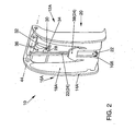
- FIG. 1 shows a side view of an installation body, in particular a headrest 20.
- the headrest 20 has a first cover element 14A.
- the first cover member 14A is connected to the headrest 20 on a first pivot axis 44.
- the first cover element 14A further has a holding element 48.
- the first cover element 14A corresponds externally to a first contour 16A, which corresponds to the shape of a headrest in a conventional manner.
- a first space 12A is provided, in which the other components are arranged belonging to a device 10.
- the device 10 comprises the first cover element 14A, in which substantially a web-like element 28, a rod 22, rod members 38 and - not visible in this figure - transmission bracket 40 and connecting bracket 42 in non-use position of the device 10 are accommodated so that they from the outside considered invisible.
- the rod 22, the rod member 38, the transmission bracket 40 and the connecting bracket 42 will be discussed in more detail in the following figures 2 and 3.
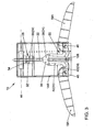
- FIG. 2 shows a perspective inside view of the installation body in this embodiment of the headrest 20 in the non-use position of the device 10.
- FIG. 2 again shows the first pivot axis 44 about which the first cover element 14A is pivotably mounted.
- a guide element 32 is arranged in the headrest 20, which has the contour 16A in the region of the cover element 14A.
- the guide element 32 is located in the region of the mounting body 20 in the space provided 12A.
- the guide element 32 has a first recess 34 and a second recess 36.
- the bow-shaped elements 34 are still in the non-use position substantially vertically and parallel to the edge region of the cover 14A.
- the web-like element 28 engages in the non-use position in the first recess 34 a.
- the web-like element 28 is also firmly connected to the rod 22.
- the rod 22 terminates in the lower part of the first cover 14A in the support member 48 (not visible in this view), wherein on the rod 22, a spring element 108 is arranged.
- the spring element 108 is supported in the holding element 48 and acts with its spring force on the rod 22.
- the rod 22 remains so long in non-use position and is fixed in the first recess 34 by the web-like element 28 in the guide member 32 until a vehicle occupant, in particular an occupant seated on a rear seat operating the first cover member 14A and pivoting the first cover member 14A about the first pivot shaft 44.
- the web-like element 28 has to support the movement on the guide member 32 has a movable component 30, which moves after pivoting of the first cover member 14A on the guide member 32 from the first recess 34 in the second recess 36.
- a movement of the rod 22 is achieved vertically upwards.
- the rod 22 is connected by the transmission elements 24, visible in Figure 2, in particular via the rod members 38, with the bow-shaped elements 18A.
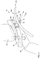
- FIG. 3 shows an inside view of the installation body, in particular the headrest 20, in the position of use of the device 10.
- This use position is achieved, as described in FIG. 2, by folding the cover element 14A about the first pivot axis 44 by the headrest 20.
- the web-like element 28 is now - caused by the spring element 108 - in the second recess 36 above the first recess 34.
- the movable component 30 slides in this movement along the guide member 32 along.
- the bar members 38 fixedly connected to the rod 22 are thus moved vertically upwards.
- the rod members 38 are connected to the transfer straps 40, which are also moved vertically upwards.
- the transmission bracket 40 are arranged on a circular path extending on the rotatably arranged, bow-shaped element 18A, perform the bow-shaped elements 18A, a rotor movement.
- the connecting bracket 42 between the first bow-shaped member 18 A and the transfer bracket 40 the rotational movement of the bow-shaped elements 18 A is performed about a rotation axis 46.
- the rod 22 may also be designed as a rack, wherein the rod members 38 then correspondingly have teeth which engage in the teeth of the rack, whereby also a vertical movement of the rod members 38 can be evoked.
- the device 10 In the position of use, the device 10 has a relaxed spring element 108.
- the rod 22 breaks through in the position of use, the first cover 14 A in a designated opening 26 in the upper region of the cover 14 A.
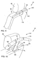
- FIG 4 shows a perspective view of another mounting body in a further embodiment, in particular a console 50 in the position of use of the device 10.
- the console 50 is preferably arranged in the embodiment between the headrest 20 and a backrest 88.
- the bracket 50 has a sliding element 52, which is arranged displaceably on an axis 60 in a displacement direction 64.
- the sliding element 52 has a first hinge 54, which is preferably arranged on the axis 60. In the position of use shown in Figure 4, the hinge 54 is connected to a connecting element 56 and folded on a second pivot axis 62 by 90 °.
- the connecting element 56 carries at least one second bow-shaped element 18B.
- the second bow-shaped element 18B is arranged centrally on the connecting element 56, so that a full-fledged hanger is formed.
- This second bow-shaped element 18B has a second contour 14B and at the same time constitutes a second cover element 14B in the non-use position
- Non-use position can be reached by starting from Figure 4, the connecting element 56 is folded on the second pivot axis 62 by 90 ° and thus arranged on the axis 60 in alignment.
- the sliding element 52 is pushed into a recess 58, wherein the cover 14B occupies the second contour 16B of the console 50 in a second - in the console 50 - space 12B provided for this purpose.
- the console 50 is disposed on a known headrest mount 72. According to the invention, the console 50 is arranged adjustable in height. In Figure 4, a first clamping sleeve element 74 is already visible. On the height adjustment is discussed in Figure 8 in more detail.
- Figures 5 to 7 show first detailed solutions of the leadership and attachment of the second ⁇ bdeckettis 14B.
- FIG. 5 shows a first solution.
- the sliding element 52 is shown in the position of use of the bow-shaped element 18B.
- the sliding element 52 is displaced in the sliding direction 64 along the axis 60.
- the first hinge 54 is also transferred to a second position.
- a connecting element 56 is not present in this FIG.
- the second bow-shaped holding element 18 B is connected to the end face with a linkage device 66.
- the linkage device 66 makes it possible that during the movement of the second bow-shaped holding element 18B in the position of use by the linkage device 66, a kind of boundary for the second bow-shaped holding element 18B is formed.
- the linkage device 66 is connected at a point inside the console 50 to the console 50 and secures or generates sufficient stability of the second bow-shaped retaining element 18B.
- FIG. 6 shows the second bracket-shaped retaining element 18B in the non-use position.
- the device 10 is seated inside the console 50.
- the first hinge 54 is disposed on the axle 60. If the sliding element 52 is moved in the sliding direction 64, the sliding element and the other elements of the device 10 occupy the position of use of the second bow-shaped retaining element 18B.
- Figure 7 shows the same parts with the same reference numerals, wherein the second bow-shaped holding elements 18B on the latching rail 68 side facing teeth 70 which engage in the locking rail 68. In this way, also takes place a backup and desired adjustment of the second bow-shaped retaining element 18B.
- FIG. 8 shows a section through the bracket 50 in the region of the headrest support 72 when the device 10 is not in use.
- the device 10 is arranged above the backrest 88.
- This height adjustment device on the Kopf providedntialt für, 72 is important for the comfort of the user as adjustment, since in this embodiment, no height adjustment can be realized with the headrest 20.
- the first Spannhüllelement 74 - as already mentioned in Figure 4 - inside the console 50 has a cover, so that the first Spannhüllelement 74 is not visible when the second bow-shaped support member 18 B is in the position of use.
- the first clamping sleeve element 74 is opposed by a second clamping sleeve element 76.
- a pressure plate 82 is disposed within the console 50.
- the height adjustment device further comprises a conical element 84, a first screw member 78 for fixing the cover member 80 and a second screw 86 with a stop 110 for fixing the second Spannhülliatas 76 relative to the first Spannhüllelement 74.
- By turning the second screw 86 is on the pressure plate 82 a Transfer force to the second clamping sleeve element 76, whereby the Spannhüllmaschine 74 and 76 are reversibly braced on the headrest bracket 72.
- the second screw 76 is guided for the purpose of operation in the console 50 to the outside.
- FIG. 9 shows a perspective view of a further possible installation body in a further embodiment, in particular the backrest 88 in the inoperative position of the device 10.
- the backrest 88 Integrated in the backrest 88 is the headrest 20 with the associated headrest supports 72 and a shaft 112 inside the backrest 88 is arranged.
- a third cover element 14C is arranged in the backrest 88, which forms a third space 12C provided on an upper side 90 of the backrest 88, which becomes visible only in FIG. 10, a third cover element 14C is arranged.
- the third cover member 14C has a third contour 16C, which in this embodiment is not visible in the non-use position of FIG.
- the third cover member 14C is, as shown in Figure 10, from the non-use position to the use position by pulling it out into a third bow-shaped element 18C. transferable.
- the shaft 112 visible in FIG. 10 is shown in a perspective view of the mounting body in the further embodiment, in particular the backrest 88, in the position of use of the device 10.
- the well 112 runs below the intended space 12C for the third cover member 14C in one Extension of a kind of recess 106.
- Through the recess 106 is formed in the backrest 88 is a kind of handle for operating the third bow-shaped holding member 18C.
- a support member 92 is arranged in the shaft 112.
- the support member 92 carries a connecting member 94.
- the connecting member 94 is preferably designed such that it corresponds to the recess 106.
- the connecting member 94 is followed by the or the third bow-like element (s) 18C, which (s) in the position of use approximately behind the headrest 20 is / are.
- the third bow-like element 18C is articulated, so that the third bow-shaped elements 18C are not arranged directly on a first horizontal axis 104 in the position of use.
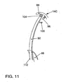
- Figure 11 shows in a section some details through the support member 92 in the backrest 88 in the position of use of the device 10.
- the support member 92 is shown pulled out of the slot 112.
- a second joint 102 is visible on the connecting member 94.
- This second hinge 102 makes it possible to tilt the connecting member 94 and thus the third bow-shaped element 18C until it comes to rest on an adjusting element 96.
- the support member 92 has a stop 100, which provides in the movement of the support member 92 from the use position in the non-use position for an accurate fixation of the support member 92 in the backrest 88.
- the stop 100 corresponds to a groove 98, not shown, at the upper edge of the shaft 112.
- the stop 100 engages in the non-use position in the groove 98 a.
Landscapes
- Engineering & Computer Science (AREA)
- Mechanical Engineering (AREA)
- Aviation & Aerospace Engineering (AREA)
- Transportation (AREA)
- Seats For Vehicles (AREA)
- Chair Legs, Seat Parts, And Backrests (AREA)
- Vehicle Step Arrangements And Article Storage (AREA)
Abstract
Description
Die Erfindung betrifft eine Vorrichtung zum Aufhängen von Gegenständen, insbesondere Kleiderstücken in einem Kraftfahrzeug, mit den im Oberbegriff des Anspruchs 1 genannten Merkmalen.The invention relates to a device for suspending objects, in particular garments in a motor vehicle, with the features mentioned in the preamble of claim 1.
Es ist bekannt, dass zumeist bei Reiseantritt, insbesondere bei längeren Reisen mit dem Auto, dem Zug, dem Flugzeug oder per Schiff, die Notwendigkeit besteht, seine Kleidungsstücke so unterzubringen, dass sie während der Reise sicher verstaut sind und dabei möglichst faltenfrei und unverschmutzt bleiben.It is known that usually when traveling, especially on longer trips by car, train, plane or boat, there is a need to accommodate his garments so that they are safely stowed while traveling and remain as wrinkle-free and unpolluted ,
In den meisten Kraftfahrzeugen befinden sich dazu im Bereich der Rücksitze oder über den Seitenfenstem vorgesehene Kleiderhaken, an denen zum Beispiel ein Jackett oder dergleichen aufgehangen werden kann. Oft wird jedoch dazu ein Kleiderbügel verwendet und der Kleiderbügel an diesem Haken aufgehängt. So aufgehängte Kleidungsstücke beeinträchtigen erheblich die Fahrsicherheit, da massive Sichtbehinderungen die Folge sind. Ferner stören die Kleiderstücke Mitreisende beim Zugang zum Rücksitz.In most motor vehicles, there are clothes hooks provided in the area of the rear seats or over the side windows, to which, for example, a jacket or the like can be hung. Often, however, a hanger is used and the hanger is hung on this hook. Such suspended garments significantly affect the driving safety, as massive obstructions are the result. Furthermore, the pieces of clothing disturb passengers when accessing the back seat.
Aus der Druckschrift
Es existieren nach dem Stand der Technik weitere Lösungen, bei denen Vorrichtungen zum Aufhängen von Kleidungsstücken in bügelförmige, Haltegriffe integriert sind. Die
Die
Weiterhin sind Lösungen bekannt, bei denen Bemühungen erkennbar sind, die Unterbringung von Vorrichtungen dieser Art möglichst unsichtbar anzuordnen. So offenbart das Gebrauchsmuster
Als nächstliegender Stand der Technik ist schließlich die
Ausgehend von dem eingangs erwähnten Stand der Technik und dessen Nachteilen liegt der Erfindung daher die Aufgabe zugrunde, ein Kraftfahrzeug der als bekannt vorausgesetzten Art so auszubilden, dass eine Vorrichtung zum Aufhängen von Gegenständen, insbesondere Kleiderstücken, in diesem Kraftfahrzeug möglich ist, ohne dass das Design eines Kraftfahrzeugsitzes in der Nichtgebrauchsstellung diese Vorrichtung vermuten lässt. Ferner ist es die Aufgabe, die Vorrichtung möglichst flexibel verstellbar zu gestalten, und sie so anzuordnen, dass im Crash-Fall eine weitestgehende Rückführung der Vorrichtung von der Gebrauchsstellung in die Nichtgebrauchsstellung ermöglicht wird.Based on the above-mentioned prior art and its disadvantages, the invention therefore has the object of providing a motor vehicle of the type assumed to be known in such a way that a device for hanging objects, in particular clothes, in this motor vehicle is possible without that the design of a motor vehicle seat in the non-use position suggests this device. Furthermore, it is the task to make the device as flexible as possible adjustable, and to arrange them so that in the event of a crash, a largely return of the device from the use position is made possible in the non-use position.
Diese Aufgabe wird durch eine Vorrichtung der eingangs genannten Art gemäß
In besonders vorteilhafter Weise ist das bügelförmige Element in seiner Nichtgebrauchsstellung vollständig im Einbaukörper integriert und nicht sichtbar, insbesondere aus Sicht eines Designers ist diese Möglichkeit von besonderem Vorteil, da Flächen frei von Vorrichtungen auf den jeweiligen Abdeckelementen entworfen werden können.In a particularly advantageous manner, the bow-shaped element is completely integrated in its non-use position in the mounting body and not visible, especially from the perspective of a designer, this option is particularly advantageous, since surfaces can be designed free of devices on the respective cover elements.
Das bügelförmige Element ist durch seine Integration praktisch handhabbar und steht stets zur Verfügung. Je nach Ausführung besteht zudem die Möglichkeit der Höhenverstellbarkeit.The bow-shaped element is practically manageable due to its integration and is always available. Depending on the version, there is also the possibility of height adjustment.
Somit ist! das bügelförmige Element an den jeweiligen Nutzer anpassbar. Das bügelförmige Element stellt nicht nur eine Hilfsvorrichtung dar, sondern kann als vollwertiger Kleiderbügel betrachtet und benutzt werden.Thus is! the bow-shaped element adaptable to the respective user. The bow-shaped element is not only an auxiliary device, but can be considered and used as a full hanger.
In bevorzugter Ausgestaltung der Erfindung bildet ein erstes Abdeckelement, in einem dafür vorgesehenen ersten Raum, eine erste Kontur eines Teiles des Einbaukörpers aus. Dieser Einbaukörper ist beispielsweise eine Kopfstütze, die mittels Kopfstützenhalterungen an der Rückenlehne des Kraftfahrzeugsitzes befestigt ist. Das erste Abdeckelement ist drehbeweglich auf einer ersten Achse gelagert und ermöglicht somit, dass die Kopfstütze in dem das Abdeckelement aufweisenden Teil des Einbaukörpers öffenbar und schließbar ist.In a preferred embodiment of the invention, a first cover, in a designated first space, forms a first contour of a part of the mounting body. This mounting body is, for example, a headrest, which is fastened by means of headrest mounts to the backrest of the motor vehicle seat. The first cover is rotatably mounted on a first axis and thus allows the headrest in the cover member having the part of the mounting body can be opened and closed.
Auf der der Kopfstütze zugewandten Seite des ersten Abdeckelementes sind erfindungsgemäß eine Stange, Übertragungselemente, mindestens ein erstes Ver- und Entriegelungselement sowie mindestens ein erstes bügelförmiges Element angeordnet. Das erste bügelförmige Element ist auf einer Drehachse drehbeweglich in einem Halteelement angeordnet, wobei das Halteelement mit dem mindestens einen ersten Abdeckelement verbunden ist. Ferner ist das mindestens eine erste Ver- und Entriegelungselement als ein zur Kopfstütze gerichtetes, stegartiges Element ausgebildet, welches an seinem Ende eine bewegliche Komponente aufweist. Das stegartige Element ist mit der Stange verbunden. Des Weiteren weist die Kopfstütze, die im Einbaukörper selbst angeordnet ist, ein Führungselement mit mindestens einer ersten und einer zweiten Aussparung auf, die unterschiedliche Tiefen besitzen.On the side facing the headrest side of the first cover according to the invention a rod, transmission elements, at least a first and Unlocking element and arranged at least a first bow-shaped element. The first bow-shaped element is rotatably arranged on a rotation axis in a holding element, wherein the holding element is connected to the at least one first cover member. Further, the at least one first locking and unlocking element is designed as a directed to the headrest, web-like element having at its end a movable component. The web-like element is connected to the rod. Furthermore, the headrest, which is arranged in the mounting body itself, a guide element having at least a first and a second recess, which have different depths.
In weiterer bevorzugter Ausgestaltung der Erfindung umfassen die Übertragungselemente mindestens ein Stangenglied, mindestens einen beweglichen. Übertragungsbügel, mindestens einen beweglichen Verbindungsbügel und mindestens ein Federelement. Der mindestens eine bewegliche Übertragungsbügel ist einerseits mit dem Stangenglied und andererseits mit dem mindestens einen bügelförmigen Element verbunden. Der mindestens eine bewegliche Verbindungsbügel ist einerseits mit dem Übertragungsbügel und andererseits mit dem mindestens einen bügelförmigen Element verbunden.In a further preferred embodiment of the invention, the transmission elements comprise at least one rod member, at least one movable. Transmission bracket, at least one movable connecting bracket and at least one spring element. The at least one movable transmission bracket is connected on the one hand to the rod member and on the other hand to the at least one bow-shaped element. The at least one movable connecting bracket is connected on the one hand to the transmission bracket and on the other hand to the at least one bow-shaped element.
In einer weiteren Ausführungsform ist in bevorzugter Ausführung ein zweites Abdeckelement in einem zweiten dafür vorgesehenen Raum angeordnet, wobei das zweite Abdeckelement in diesem Raum eine zweite Kontur eines Teiles des Einbaukörpers einnimmt. Dieser Einbaukörper ist in dieser Ausführungsform insbesondere eine Konsole, die vorzugsweise zwischen der Kopfstütze und einer die Kopfstütze tragenden Rückenlehne angeordnet ist. Das zweite Abdeckelement umfasst ein Schiebeelement, welches entlang einer Achse ein erstes Gelenk aufweist und in Schieberichtung reversibel verlagerbar ist. Das erste Gelenk verbindet das Schiebeelement mit einem Verbindungselement, welches in bevorzugter . Ausführung der Erfindung ein zweites bügelförmiges Element aufweist. Das zweite Schiebeelement ermöglicht die Vorrichtung aus einer Nichtgebrauchsstellung in die Gebrauchsstellung zu verlagern, wobei das Schiebeelement selbst in einer Ausnehmung der Konsole anordbar ist. Das Erreichen der Gebrauchsstellung wird in einer bevorzugten Ausführungsvariante dadurch erreicht, dass das Schiebeelement in. Schieberichtung verschoben wird und anschließend am ersten Gelenk um eine zweite Schwenkachse, vorzugsweise um 90°; geklappt wird.In a further embodiment, in a preferred embodiment, a second cover element is arranged in a second space provided for this purpose, wherein the second cover element occupies a second contour of a part of the installation body in this space. This mounting body is in this embodiment in particular a console, which is preferably arranged between the headrest and a headrest supporting the backrest. The second cover element comprises a sliding element which has a first joint along an axis and is reversibly displaceable in the sliding direction. The first joint connects the sliding element with a connecting element, which in a preferred. Embodiment of the invention comprises a second bow-shaped element. The second sliding element allows the device to be displaced from a non-use position into the use position, wherein the sliding element itself can be arranged in a recess of the console. Achieving the use position is achieved in a preferred embodiment, characterized in that the sliding element is moved in. Sliding direction and then at the first joint about a second pivot axis, preferably by 90 °; is worked.
Zur Begrenzung und Justage der Klappbewegung weist das zweite bügelförmige Halteelement entweder eine Gestängevorrichtung oder eine Rastschiene mit im bügelförmigen Element angeordneten Zähnen auf. Die Gestängevorrichtung begrenzt die Klappbewegung durch eine entsprechende Gestängelänge und in einer zweiten Ausführungsform greifen die Zähne des zweiten bügelförmigen Halteelementes in die Rastschiene ein.For limiting and adjusting the folding movement, the second bow-shaped holding element has either a linkage device or a latching rail with teeth arranged in the bow-shaped element. The linkage device limits the Folding movement by a corresponding rod length and in a second embodiment, the teeth of the second bow-shaped holding element engage in the latching rail.
In bevorzugter Ausführung ist die Konsole mittels einer Arretierungsvorrichtung an den Kopfstützenhalterungen reversibel verschiebbar und arretierbar, wodurch in vorteilhafter Weise eine Höhenverstellung des zweiten bügelförmigen Halteelementes erreichbar ist.In a preferred embodiment, the console is reversibly displaceable and lockable by means of a locking device on the headrest holders, whereby advantageously a height adjustment of the second bow-shaped holding element can be achieved.
Bevorzugt ist in einer weiteren Ausführungsvariante, dass ein drittes Abdeckelement, in einem dafür vorgesehenen dritten Raum, eine dritte Kontur eines Teils des Einbaukörpers, insbesondere der Rückenlehne, vorzugsweise an einer Oberseite der Rückenlehne einnimmt. Das dritte Abdeckelement weist dabei ein Stützelement auf, welches in einem in der Rückenlehne dafür vorgesehenen Schacht angeordnet ist. Das Stützelement weist einendseitig ein Verbindungsglied auf, an dem mindestens ein drittes bügelförmiges Element angeordnet ist.In a further embodiment variant, it is preferred that a third cover element, in a third space provided for this purpose, occupies a third contour of a part of the installation body, in particular the backrest, preferably on an upper side of the backrest. In this case, the third cover element has a support element which is arranged in a shaft provided in the backrest for this purpose. The support member has at one end a connecting member on which at least a third bow-shaped element is arranged.
Bevorzugt ist ferner, dass das Stützelement mindestens einen Anschlag ausbildet und vorzugsweise ein zweites Gelenk aufweist, welches die Verbindung zwischen dem Stützelement und dem Verbindungsglied herstellt. Das zweite Gelenk verläuft auf einer im Wesentlichen horizontalen Achse.It is further preferred that the support element forms at least one stop and preferably has a second joint, which establishes the connection between the support element and the connecting member. The second joint runs on a substantially horizontal axis.
Die Gebrauchsstellung ist durch Herausziehen des Stützelementes aus einem in der Rückenlehne angeordneten Schacht erreichbar, wodurch sich direkt das mindestens eine dritte bügelförmige Element, welches an dem Verbindungsglied angeordnet ist, ausbildet.The use position can be reached by pulling out of the support member from a arranged in the back of the shaft, which directly forms the at least one third bow-shaped element, which is arranged on the connecting member forms.
Weitere bevorzugte Ausgestaltungen der Erfindung ergeben sich aus den übrigen, in den Unteransprüchen genannten Merkmalen.Further preferred embodiments of the invention will become apparent from the remaining, mentioned in the dependent claims characteristics.
Die Erfindung wird nachfolgend in Ausführungsbeispielen anhand der zugehörigen Zeichnungen näher erläutert. Es zeigen:
- Figur 1
- eine Seitenansicht eines Einbaukörpers, insbesondere einer Kopfstütze, in Gebrauchsstellung einer Vorrichtung;
Figur 2- eine perspektivische Innenansicht des Einbaukörpers, insbesondere der Kopfstütze, in Nichtgebrauchsstellung der Vorrichtung;
- Figur 3
- eine Innenansicht des Einbaukörpers, insbesondere der Kopfstütze, in Gebrauchsstellung der Vorrichtung;
- Figur 4
- eine perspektivische Ansicht eines Einbaukörpers in einer weiteren Ausführungsform, insbesondere einer Konsole, in Gebrauchsstellung der Vorrichtung;
- Figur 5
- einen Schnitt auf einer Achse durch die Konsole im Bereich der Vorrichtung in einer Ausführungsform in Gebrauchsstellung;
- Figur 6
- einen Schnitt auf der Achse durch die Konsole im Bereich der Vorrichtung in einer weiteren Ausführungsform in Nichtgebrauchsstellung;
- Figur 7
- einen Schnitt auf der Achse durch die Konsole im Bereich der Vorrichtung in der weiteren Ausführungsform in Gebrauchsstellung;
- Figur 8
- einen Schnitt durch die Konsole im Bereich einer Kopfstützenhalterung in Nichtgebrauchsstellung der Vorrichtung;
- Figur 9
- eine perspektivische Ansicht eines Einbaukörpers in einer weiteren Ausführungsform, insbesondere einer Rückenlehne, in Nichtgebrauchsstellung der Vorrichtung;
Figur 10- eine perspektivische Ansicht eines Einbaukörpers in der weiteren Ausführungsform, insbesondere der Rückenlehne, in Gebrauchsstellung der Vorrichtung und
- Figur 11
- einen Schnitt durch ein Stützelement im Einbaukörper, insbesondere der Rückenlehne, in Gebrauchsstellung der Vorrichtung.
- FIG. 1
- a side view of an installation body, in particular a headrest, in the use position of a device;
- FIG. 2
- an internal perspective view of the mounting body, in particular the headrest, in non-use position of the device;
- FIG. 3
- an inside view of the mounting body, in particular the headrest, in the position of use of the device;
- FIG. 4
- a perspective view of an installation body in a further embodiment, in particular a console, in the position of use of the device;
- FIG. 5
- a section on an axis through the console in the region of the device in an embodiment in the position of use;
- FIG. 6
- a section on the axis through the console in the region of the device in a further embodiment in non-use position;
- FIG. 7
- a section on the axis through the console in the region of the device in the further embodiment in the position of use;
- FIG. 8
- a section through the console in the region of a headrest bracket in non-use position of the device;
- FIG. 9
- a perspective view of an installation body in a further embodiment, in particular a backrest, in non-use position of the device;
- FIG. 10
- a perspective view of an installation body in the further embodiment, in particular the backrest, in the use position of the device and
- FIG. 11
- a section through a support element in the mounting body, in particular the backrest, in the position of use of the device.
Figur 1 zeigt eine Seitenansicht eines Einbaukörpers, insbesondere eine Kopfstütze 20. Die Kopfstütze 20 weist ein erstes Abdeckelement 14A auf. Das erste Abdeckelement 14A ist auf einer ersten Schwenkachse 44 mit der Kopfstütze 20 verbunden. Das erste Abdeckelement 14A weist ferner ein Halteelement 48 auf. Das erste Abdeckelement 14A entspricht äußerlich einer ersten Kontur 16A, die der Form einer Kopfstütze in herkömmlicher Weise entspricht. In der Kopfstütze 20 ist ein erster Raum 12A vorgesehen, in dem die weiteren Bestandteile zu einer Vorrichtung 10 gehörend angeordnet sind. Die Vorrichtung 10 umfasst das erste Abdeckelement 14A, in dem im Wesentlichen ein stegartiges Element 28, eine Stange 22, Stangenglieder 38 und - in dieser Figur nicht sichtbar - Übertragungsbügel 40 sowie Verbindungsbügel 42 in Nichtgebrauchsstellung der Vorrichtung 10 so unterbringbar sind, dass sie von außen betrachtet nicht sichtbar sind. Auf die Übertragungselemente 24, die Stange 22, das Stangenglied 38, den Übertragungsbügel 40 sowie den Verbindungsbügel 42 wird näher in den folgenden Figuren 2 und 3 eingegangen.FIG. 1 shows a side view of an installation body, in particular a
Figur 2 zeigt eine perspektivische Innenansicht des Einbaukörpers in diesem Ausführungsbeispiel der Kopfstütze 20 in Nichtgebrauchsstellung der Vorrichtung 10. Zunächst zeigt Figur 2 wiederum die erste Schwenkachse 44, um die das erste Abdeckelement 14A schwenkbar gelagert ist. In der Kopfstütze 20, die im Bereich des Abdeckelementes 14A die Kontur 16A aufweist, ist ein Führungselement 32 angeordnet. Das Führungselement 32 liegt im Bereich des Einbaukörpers 20 in dem dafür vorgesehenen Raum 12A. Das Führungselement 32 weist eine erste Aussparung 34 und eine zweite Aussparung 36 auf. Die bügelförmigen Elemente 34 befinden sich noch in Nichtgebrauchsstellung im Wesentlichen vertikal und parallel zum Randbereich des Abdeckelementes 14A. Das stegartige Element 28 greift in Nichtgebrauchsstellung in die erste Aussparung 34 ein. Das stegartige Element 28 ist zudem fest mit der Stange 22 verbunden. Die Stange 22 endet im unteren Teil des ersten Abdeckelementes 14A im Halteelement 48 (in dieser Ansicht nicht sichtbar), wobei auf der Stange 22 ein Federelement 108 angeordnet ist. Das Federelement 108 stützt sich im Halteelement 48 ab und wirkt mit seiner Federkraft auf die Stange 22. Die Stange 22 bleibt jedoch so lange in Nichtgebrauchsstellung und ist in der ersten Aussparung 34 durch das stegartige Element 28 im Führungselement 32 fixiert, bis ein Fahrzeuginsasse, insbesondere ein auf einer Rücksitzbank sitzender Insasse, das erste Abdeckelement 14A bedient und das erste Abdeckelement 14A um die erste Schwenkachse 44 geschwenkt wird. Das stegartige Element 28 besitzt zur Unterstützung der Bewegung auf dem Führungselement 32 eine bewegliche Komponente 30, die sich nach Schwenken des ersten Abdeckelementes 14A auf dem Führungselement 32 aus der ersten Aussparung 34 in die zweite Aussparung 36 bewegt. Dadurch wird, durch das vorgespannte Federelement 108 hervorgerufen, eine Bewegung der Stange 22 vertikal nach oben gerichtet erreicht. Die Stange 22 ist durch die Übertragungselemente 24, in Figur 2 sichtbar, insbesondere über die Stangenglieder 38, mit den bügelförmigen Elementen 18A verbunden.FIG. 2 shows a perspective inside view of the installation body in this embodiment of the
Figur 3 zeigt eine Innenansicht des Einbaukörpers, insbesondere der Kopfstütze 20, in Gebrauchsstellung der Vorrichtung 10. Diese Gebrauchsstellung wird erreicht, wie in Figur 2 beschrieben, indem das Abdeckelement 14A von der Kopfstütze 20 um die erste Schwenkachse 44 geklappt wird. Das stegartige Element 28 befindet sich nun - hervorgerufen durch das Federelement 108 - in der zweiten Aussparung 36 oberhalb der ersten Aussparung 34. Die bewegliche Komponente 30 gleitet bei dieser Bewegung am Führungselement 32 entlang. Die mit der Stange 22 fest verbundenen Stangenglieder 38 werden somit vertikal nach oben bewegt. Die Stangenglieder 38 sind mit den Übertragungsbügeln 40 verbunden, die ebenfalls vertikal nach oben mitbewegt werden. Dadurch, dass die Übertragungsbügel 40 auf einer Kreisbahn verlaufend auf dem drehbeweglich angeordneten, bügelförmigen Element 18A angeordnet sind, vollführen die bügelförmigen Elemente 18A eine rotorische Bewegung. Durch die Verbindungsbügel 42 zwischen dem ersten bügelförmigen Element 18A und dem Übertragungsbügel 40 wird die Rotationsbewegung der bügelförmigen Elemente 18A um eine Drehachse 46 ausgeführt.FIG. 3 shows an inside view of the installation body, in particular the
In einer weiteren, jedoch nicht näher dargestellten Ausführungsform kann die Stange 22 auch als Zahnstange ausgeführt sein, wobei die Stangenglieder 38 dann entsprechend Zähne aufweisen, die in die Zähne der Zahnstange eingreifen, wodurch ebenfalls eine vertikale Bewegung der Stangenglieder 38 hervorrufbar ist.In a further, but not shown embodiment, the
In der Gebrauchsstellung weist die Vorrichtung 10 ein entspanntes Federelement 108 auf. Die Stange 22 durchbricht in Gebrauchsstellung das erste Abdeckelement 14A in einer dafür vorgesehenen Öffnung 26 im oberen Bereich des Abdeckelementes 14A.In the position of use, the
Figur 4 zeigt eine perspektivische Ansicht eines weiteren Einbaukörpers in einer weiteren Ausführungsform, insbesondere eine Konsole 50 in Gebrauchsstellung der Vorrichtung 10. Die Konsole 50 ist im Ausführungsbeispiel vorzugsweise zwischen der Kopfstütze 20 und einer Rückenlehne 88 angeordnet. Die Konsole 50 weist ein Schiebeelement 52 auf, welches auf einer Achse 60 in einer Verschieberichtung 64 verschiebbar angeordnet ist. Das Schiebeelement 52 weist ein erstes Gelenk 54 auf, welches vorzugsweise auf der Achse 60 angeordnet ist. In der in Figur 4 gezeigten Gebrauchsstellung ist das Gelenk 54 mit einem Verbindungselement 56 verbunden und auf einer zweiten Schwenkachse 62 um 90° geklappt. Das Verbindungselement 56 trägt mindestens ein zweites bügelförmiges Element 18B. Im Ausführungsbeispiel der Figur 4 ist das zweite bügelförmige Element 18B mittig auf dem Verbindungselement 56 angeordnet, so dass ein vollwertiger Kleiderbügel entsteht. Dieses zweite bügelförmige Element 18B weist eine zweite Kontur 14B auf und stellt gleichzeitig ein zweites Abdeckelement 14B in der Nichtgebrauchsstellung dar. Die Nichtgebrauchsstellung ist erreichbar, indem ausgehend von Figur 4 das Verbindungselement 56 auf der zweiten Schwenkachse 62 um 90° geklappt wird und somit auf der Achse 60 fluchtend angeordnet ist. Anschließend wird das Schiebeelement 52 in eine Aussparung 58 geschoben, wobei das Abdeckelement 14B die zweite Kontur 16B der Konsole 50 in einem zweiten - in der Konsole 50 - dafür vorgesehenen Raum 12B einnimmt. Die Konsole 50 ist an einer bekannten Kopfstützenhalterung 72 angeordnet. Erfindungsgemäß ist die Konsole 50 höhenverstellbar angeordnet. In Figur 4 wird bereits ein erstes Spannhüllelement 74 sichtbar. Auf die Höhenverstellbarkeit wird in Figur 8 noch näher eingegangen.Figure 4 shows a perspective view of another mounting body in a further embodiment, in particular a
Die Figuren 5 bis 7 zeigen zunächst Detaillösungen der Führung und Befestigung des zweiten Äbdeckelementes 14B.Figures 5 to 7 show first detailed solutions of the leadership and attachment of the
Figur 5 zeigt eine erste Lösung. In der Konsole 50 ist das Schiebeelement 52 in Gebrauchsstellung des bügelförmigen Elementes 18B dargestellt. Das Schiebeelement 52 ist in Schieberichtung 64 entlang der Achse 60 verschoben. Das erste Gelenk 54 ist ebenfalls in eine zweite Position überführt. Ein Verbindungselement 56 ist in dieser Figur 5 nicht vorhanden. Das zweite bügelförmige Halteelement 18B ist stirnseitig mit einer Gestängevorrichtung 66 verbunden. Die Gestängevorrichtung 66 ermöglicht, dass bei der Bewegung des zweiten bügelförmigen Halteelementes 18B in Gebrauchsstellung durch die Gestängevorrichtung 66 eine Art Begrenzung für das zweite bügelförmige Halteelement 18B ausgebildet ist. Die Gestängevorrichtung 66 ist an einem Punkt im Inneren der Konsole 50 mit der Konsole 50 verbunden und sichert beziehungsweise erzeugt ausreichend Stabilität des zweiten bügelförmigen Halteelementes 18B.FIG. 5 shows a first solution. In the
Figuren 6 und 7 zeigen eine andere Lösung. Das Schiebeelement 52 in der Konsole 50 besitzt eine Rastschiene 68. Figur 6 zeigt das zweite bügelförmige Halteelement 18B in der Nichtgebrauchsstellung. Die Vorrichtung 10 sitzt im Inneren der Konsole 50. Das erste Gelenk 54 ist auf der Achse 60 angeordnet. Wird das Schiebelement 52 in Schieberichtung 64 bewegt, nimmt das Schiebelement und die weiteren Elemente der Vorrichtung 10 die Gebrauchsstellung des zweiten bügelförmigen Halteelementes 18B ein. Figur 7 zeigt dabei die gleichen Teile mit gleichen Bezugszeichen, wobei das zweite bügelförmige Halteelemente 18B auf der der Rastschiene 68 zugewandten Seite Zähne 70 aufweist, die in die Rastschiene 68 eingreifen. Auf diese Weise findet ebenfalls eine Sicherung und gewünschte Justierung des zweiten bügelförmigen Halteelementes 18B statt.Figures 6 and 7 show another solution. The sliding
Figur 8 zeigt einen Schnitt durch die Konsole 50 im Bereich der Kopfstützenhalterung 72 in Nichtgebrauchsstellung der Vorrichtung 10. Die Vorrichtung 10 ist hierbei oberhalb der Rückenlehne 88 angeordnet. Diese Höhenverstelleinrichtung an der Kopfstützentialterung , 72 ist für den Komfort des Nutzers als Einstellmöglichkeit wichtig, da in dieser Ausführungsform keine Höhenverstellung mit der Kopfstütze 20 realisiert werden kann. Das erste Spannhüllelement 74 - wie bereits in Figur 4 erwähnt - besitzt im Inneren der Konsole 50 ein Abdeckelement, so dass das erste Spannhüllelement 74 nicht sichtbar ist, wenn das zweite bügelförmige Halteelement 18B in Gebrauchsstellung ist. Dem ersten Spannhüllelement 74 liegt ein zweites Spannhüllelement 76 gegenüber. Auf dem zweiten Spannhüllelement 76 ist eine Druckplatte 82 innerhalb der Konsole 50 angeordnet. Die Höhenverstelleinrichtung umfasst weiterhin ein Konuselement 84, ein erstes Schraubelement 78 zur Befestigung des Abdeckelementes 80 und ein zweites Schraubelement 86 mit einem Anschlag 110 zur Befestigung des zweiten Spannhüllelementes 76 gegenüber dem ersten Spannhüllelement 74. Durch Drehen des zweiten Schraubelementes 86 wird über die Druckplatte 82 eine Kraft auf das zweite Spannhüllelement 76 übertragen, wodurch die Spannhüllelemente 74 und 76 reversibel an der Kopfstützenhalterung 72 verspannt werden. Das zweite Schraubelement 76 ist zum Zwecke der Bedienung in der Konsole 50 nach außen geführt.FIG. 8 shows a section through the
Figur 9 zeigt eine perspektivische Ansicht eines weiteren möglichen Einbaukörpers in einer weiteren Ausführungsform, insbesondere der Rückenlehne 88 in Nichtgebrauchsstellung der Vorrichtung 10. In die Rückenlehne 88 integriert ist die Kopfstütze 20 mit den zugehörigen Kopfstützenhalterungen 72 und ein Schacht 112, der im Inneren der Rückenlehne 88 angeordnet ist.FIG. 9 shows a perspective view of a further possible installation body in a further embodiment, in particular the
In der Rückenlehne 88, die auf einer Oberseite 90 der Rückenlehne 88 einen dritten vorgesehenen Raum 12C ausbildet, der erst in Figur 10 sichtbar wird, ist ein drittes Abdeckelement 14C angeordnet. Das dritte Abdeckelement 14C weist eine dritte Kontur 16C auf, die in dieser Ausführungsform in der Nichtgebrauchsstellung der Figur 9 nicht sichtbar ist. Das dritte Abdeckelement 14C ist, wie Figur 10 zeigt, aus der Nichtgebrauchsstellung in die Gebrauchsstellung durch Herausziehen in ein drittes bügelförmiges Element 18C . überführbar.In the
Der in Figur 10 sichtbare Schacht 112 wird in einer perspektivischen Ansicht des Einbaukörpers in der weiteren Ausführungsform, insbesondere der Rückenlehne 88, in Gebrauchsstellung der Vorrichtung 10 gezeigt. Vorzugsweise läuft der Schacht 112 unterhalb des vorgesehenen Raumes 12C für das dritte Abdeckelement 14C in einer Erweiterung einer Art Aussparung 106 aus. Durch die Aussparung 106 bildet sich in der Rückenlehne 88 eine Art Griff zur Bedienung des dritten bügelförmigen Halteelementes 18C. Im Schacht 112 ist ein Stützelement 92 angeordnet. Das Stützelement 92 trägt ein Verbindungsglied 94. Das Verbindungsglied 94 ist vorzugsweise derart ausgeführt, dass es mit der Aussparung 106 korrespondiert. An das Verbindungsglied 94 schließen sich die oder das dritte bügelartige(n) Element(e) 18C an, welche(s) in Gebrauchsstellung in etwa hinter der Kopfstütze 20 angeordnet ist/sind. Das dritte bügelartige Element 18C ist dabei gelenkig angeordnet, so dass die dritten bügelartigen Elemente 18C in Gebrauchsstellung nicht direkt auf einer ersten horizontalen Achse 104 angeordnet sind.The
Figur 11 zeigt in einem Schnitt einige Details durch das Stützelement 92 in der Rückenlehne 88 in Gebrauchsstellung der Vorrichtung 10. Das-Stützelement 92 ist aus dem Schacht 112 herausgezogen dargestellt. Am Verbindungsglied 94 ist ein zweites Gelenk 102 sichtbar. Dieses zweite Gelenk 102 ermöglicht es, das Verbindungsglied 94 und damit das dritte bügelartige Element 18C zu kippen, bis es auf einem Justierelement 96 zur Anlage kommt. Ferner besitzt das Stützelement 92 einen Anschlag 100, der bei der Bewegung des Stützelementes 92 von der Gebrauchsstellung in die Nichtgebrauchsstellung für eine genaue Fixierung des Stützelementes 92 in die Rückenlehne 88 sorgt. Der Anschlag 100 korrespondiert mit einer nicht dargestellten Nut 98 am oberen Rand des Schachtes 112. Der Anschlag 100 greift in Nichtgebrauchsstellung in die Nut 98 ein.Figure 11 shows in a section some details through the
- 1010
- Vorrichtungcontraption
- 1212
- vorgesehener Raumprovided space
- 12A12A
- erster vorgesehener Raumfirst planned room
- 12B12B
- zweiter vorgesehener Raumsecond planned room
- 12C12C
- dritter vorgesehener Raumthird room provided
- 1414
- Abdeckelementcover
- 14A14A
- erstes Abdeckelementfirst cover element
- 14B14B
- zweites Abdeckelementsecond cover element
- 14C14C
- drittes Abdeckelementthird cover element
- 1616
- Konturcontour
- 16A16A
- erste Konturfirst contour
- 16B16B
- zweite Kontursecond contour
- 16C16C
- dritte Konturthird contour
- 1818
- bügelförmiges Elementbow-shaped element
- 18A18A
- erstes bügelförmiges Elementfirst bow-shaped element
- 18B18B
- zweites bügelförmiges Elementsecond bow-shaped element
- 18C18C
- drittes bügelförmiges Elementthird bow-shaped element
- 2020
- Kopfstütze (Einbaukörper)Headrest (installation body)
- 2222
- Stangepole
- 2424
- Übertragungselementetransmission elements
- 2626
- Öffnungopening
- 2828
- stegartiges Elementweb-like element
- 3030
- bewegliche Komponentemovable component
- 3232
- Führungselementguide element
- 3434
- erste Aussparungfirst recess
- 3636
- zweite Aussparungsecond recess
- 3838
- Stangengliedbar member
- 4040
- Übertragungsbügeltransmission bars
- 4242
- Verbindungsbügelconnecting brackets
- 4444
- erste Schwenkachsefirst pivot axis
- 4646
- Drehachseaxis of rotation
- 4848
- Halteelementretaining element
- 5050
- Konsole (Einbaukörper)Console (mounting body)
- 5252
- Schiebeelementsliding element
- 5454
- erstes Gelenkfirst joint
- 5656
- Verbindungselementconnecting element
- 5858
- Aussparungrecess
- 6060
- Achseaxis
- 6262
- zweite Schwenkachsesecond pivot axis
- 6464
- Schieberichtungsliding direction
- 6666
- Gestängevorrichtunglinkage device
- 6868
- Rastschienelocking rail
- 7070
- Zähneteeth
- 7272
- KopfstützenhalterungHeadrest mount
- 7474
- erstes Spannhüllelementfirst clamping sleeve element
- 7676
- zweites Spannhüllelementsecond clamping sleeve element
- 7878
- erstes Schraubelementfirst screw
- 8080
- Abdeckelementcover
- 8282
- Druckplatteprinting plate
- 8484
- Konuselementcone element
- 8686
- zweites Schraubelementsecond screw
- 8888
- Rückenlehne (Einbaukörper)Backrest (installation body)
- 9090
- Oberseite (Rückenlehne)Top (backrest)
- 9292
- Stützelementsupport element
- 9494
- Verbindungsgliedlink
- 9696
- Justierelementadjusting
- 9898
- Nutgroove
- 100100
- Anschlagattack
- 102102
- zweites Gelenksecond joint
- 104104
- erste horizontale Achsefirst horizontal axis
- 106106
- Aussparungrecess
- 108108
- Federelementspring element
- 110110
- Scheibedisc
Claims (31)
- Device (10) for hanging objects, in particular items of clothing, in a motor vehicle, for insertion into an insert body, in particular into a backrest and/or headrest (20) of a motor vehicle seat or the like, which device can be moved from a non-use position into a use position, wherein the device (10)• firstly, in the non-use position, has at least one covering element (14/14A, 14B, 14C) which closes a designated space (12/12A, 12B, 12C) of at least one insert body (20, 50, 88) and replicates the contour (16/16A, 16B, 16C) of the at least one insert body (20, 50, 88), and• secondly, in order to achieve the use position, comprises a hanger-shaped element (18/18A, 18B, 18C) which has movable elements (22, 24, 26, 28, 30, 34, 36, 38, 40, 42/54, 56, 66, 68, 70/94, 102), and• in the use position, the covering element (14/14A, 14B, 14C) and the movable elements (22, 24, 26, 28, 30, 34, 36, 38, 40, 42/54, 56, 66, 68, 70/94, 102) of the hanger-shaped element (18/18A, 18B, 18C), which elements belong to the covering element (14/14A, 14B, 14C), are guided in the insert body (20, 50, 88) just on elements (32, 52, 92) in the designated space (12/12A, 12B, 12C) for this in the insert body (20, 50, 88), and wherein• the hanger-shaped element (18/18A, 18B, 18C) can both be automatically formed into the use position as a function of a displacement of the covering element (14/14A, 14B, 14C), with the contour (16/16A, 16B, 16C) of the insert body (20, 50, 88) being neutralized, and can be automatically returned into the non-use position, with the contour (16/16A, 16B, 16C) being restored,characterized in that,
in the use position, the movable elements (22, 24, 26, 28, 30, 34, 36, 38, 40, 42/54, 56, 66, 68, 70/94, 102) together with the hanger-shaped element (18/18A, 18B, 18C) are formed on the covering element (14/14A, 14B, 14C) exclusively outside the at least one insert body (20, 50, 88). - Device (10) according to Claim 1, characterized in that a first covering element (14A) forms a first contour (16A) of a part of the insert body, in particular of a headrest (20), in a first designated space (12A).
- Device (10) according to Claims 1 and 2, characterized in that the first covering element (14A) can be opened, closed and mounted rotatably on a first spindle (44) on the headrest (20).
- Device (10) according to Claims 1 to 3, characterized in that the first covering element (14A) has at least one rod (22), transmission elements (24), at least one first locking and unlocking element (26) and at least one first hanger-shaped element (18A) on the side facing the headrest (20).
- Device (10) according to Claim 4, characterized in that the at least one first hanger-shaped element (18A) is arranged in a rotatable manner on a rotating spindle (46) in a holding element (48), the holding element (48) being connected to the at least one first covering element (14A).
- Device (10) according to Claim 4, characterized in that the first locking and unlocking element (26) is designed as a web-like element (28) which is directed towards the headrest (20) and has a movable component (30) at the end.
- Device (10) according to Claim 6, characterized in that the web-like element (28) is connected to the rod (22).
- Device (10) according to Claim 1, characterized in that the headrest (20) has the insert body (20) and a guide element (32) with at least one first and one second cutout (34, 36) at differing depths.
- Device (10) according to Claim 4, characterized in that the transmission elements (24) comprise at least one rod element (38), at least one movable transmission bow (40), at least one movable connecting bow (42) and at least one spring element (108).
- Device (10) according to Claim 9, characterized in that the at least one movable transmission bow (40) is firstly connected to the rod element (38) and secondly to the at least one hanger-shaped element (18A).
- Device (10) according to Claim 9, characterized in that the at least one movable connecting bow (42) is firstly connected to the transmission bow (40) and secondly to the at least one hanger-shaped element (18A).
- Device (10) according to Claim 1, characterized in that a second covering element (14B) assumes a second contour (16B) of a part of the insert body, in particular of a console (50), which is preferably arranged between the headrest (20) and a backrest (88), in a second designated space (12B).
- Device (10) according to Claim 12, characterized in that the second covering element (14B) comprises a sliding element (52) which has a first joint (54) along an axis (60) and can be displaced reversibly in the sliding direction (64).
- Device (10) according to Claim 13, characterized in that the first joint (54) has a connecting element (56).
- Device (10) according to Claim 14, characterized in that the connecting element (56) has a second hanger-shaped element (18B).
- Device (10) according to Claim 13, characterized in that the second sliding element (52) is arranged in a reversibly displaceably manner in a recess (58) of the second designated space (12B) of the console (50).
- Device (10) according to Claims 15 and 16, characterized in that, after displacement in the sliding direction (64), the second hanger-shaped element (18B) can be folded at the first joint (54) through preferably 90° about a second pivot axis (62) from its non-use position into its use position.
- Device (10) according to Claim 17, characterized in that, after the second hanger-shaped element (18B) is folded into its use position, the folding movement thereof can be restricted or adjusted by means of a linkage device (66).
- Device (10) according to Claim 17, characterized in that, after the second hanger-shaped element (18B) is folded into its functional position, the folding movement thereof can be restricted or can be adjusted in a latching rail (68) with teeth (70) arranged in the second hanger-shaped element (18B).
- Device (10) according to Claim 12, characterized in that the console (50) can be displaced reversibly and can be retained on at least one headrest mount (72) by means of a retaining device which has at least one pressure plate (82), a conical element (84), at least one second screw element (86) and a disc (110).
- Device (10) according to Claim 20, characterized in that the at least one headrest mount (72) comprises at least one first and second clamping casing element (74, 76).
- Device (10) according to Claim 21, characterized in that the at least one first clamping casing element (74) has a covering element (80) which can preferably be fastened by means of a first screw element (78).
- Device (10) according to Claims 20 and 21, characterized in that the at least one second clamping casing element (76) has a pressure plate (82) via which the second clamping casing element (76) can be retained by means of the retaining device (82, 84, 86, 110).
- Device (10) according to Claim 1, characterized in that a third covering element (14C) assumes a third contour (16C) of a part of the insert body, in particular of the backrest (88), preferably of an upper side (90) of the backrest (88), in a third designated space (12C).
- Device (10) according to Claim 24, characterized in that the third covering element (14C) has a supporting element (92), at least one connecting element (94) and at least one third hanger-shaped element (18C).
- Device (10) according to Claim 25, characterized in that, in the non-use position, the supporting element (92) is arranged in a shaft (112) in the backrest (88).
- Device (10) according to Claims 25 or 26, characterized in that the supporting element (92) forms at least one stop (100) and at least one second joint (102), which is connected to the at least one connecting element (94), is arranged preferably on the end side.
- Device (10) according to Claim 27, characterized in that the second joint (102) is arranged on an essentially horizontal axis (104).
- Device (10) according to Claim 25, characterized in that the supporting element (92) is movable reversibly out of the backrest (88) from the non-use position into the use position.
- Device (10) according to Claim 25, characterized in that, in the non-functional position, the connecting element (94) can be arranged in a cutout (106) of the third designated space (12C) and, in the functional position, bears the at least one third hanger-shaped element (18C) outside the cutout (106).
- Device (10) according to Claim 30, characterized in that the cutout (106) arranged in the backrest (88) forms a type of recessed grip below the third covering element (14C).
Applications Claiming Priority (3)
| Application Number | Priority Date | Filing Date | Title |
|---|---|---|---|
| DE10261896A DE10261896A1 (en) | 2002-12-23 | 2002-12-23 | Coat hanger with headrest |
| DE10261896 | 2002-12-23 | ||
| PCT/EP2003/013667 WO2004058536A1 (en) | 2002-12-23 | 2003-12-03 | Clothes hanger with a headrest |
Publications (2)
| Publication Number | Publication Date |
|---|---|
| EP1578639A1 EP1578639A1 (en) | 2005-09-28 |
| EP1578639B1 true EP1578639B1 (en) | 2007-08-15 |
Family
ID=32404423
Family Applications (1)
| Application Number | Title | Priority Date | Filing Date |
|---|---|---|---|
| EP03782299A Expired - Lifetime EP1578639B1 (en) | 2002-12-23 | 2003-12-03 | Clothes hanger with a headrest |
Country Status (4)
| Country | Link |
|---|---|
| EP (1) | EP1578639B1 (en) |
| AT (1) | ATE370026T1 (en) |
| DE (2) | DE10261896A1 (en) |
| WO (1) | WO2004058536A1 (en) |
Families Citing this family (20)
| Publication number | Priority date | Publication date | Assignee | Title |
|---|---|---|---|---|
| DE102005022009B4 (en) * | 2005-05-12 | 2007-12-20 | Daimlerchrysler Ag | backrest |
| CZ302099B6 (en) * | 2005-10-17 | 2010-10-13 | Škoda Auto a. s. | Coat hanger |
| DE102006001014A1 (en) * | 2006-01-05 | 2007-07-12 | Kinetix Ag | Device for suspending objects in motor vehicle has fastening mechanism which is connected with member e.g. backrest, headrest or headrest fixture plate of vehicle seat and support element is linked with fastening mechanism |
| DE102005050404A1 (en) * | 2005-10-19 | 2007-05-03 | Kinetix Ag | Device for suspending objects in motor vehicle has fastening mechanism which is connected with member e.g. backrest, headrest or headrest fixture plate of vehicle seat and support element is linked with fastening mechanism |
| DE102006003280A1 (en) * | 2006-01-23 | 2007-07-26 | Kinetix Ag | Device for suspending objects in motor vehicle has fastening mechanism which is connected with member e.g. backrest, headrest or headrest fixture plate of vehicle seat and support element is linked with fastening mechanism |
| DE102006001778A1 (en) * | 2006-01-12 | 2007-07-26 | Kinetix Ag | Device for suspending objects in motor vehicle has fastening mechanism which is connected with member e.g. backrest, headrest or headrest fixture plate of vehicle seat and support element is linked with fastening mechanism |
| DE102005051708B3 (en) * | 2005-10-28 | 2006-10-26 | Faurecia Autositze Gmbh & Co. Kg | Motor vehicle seat has a clothes hanger incorporated into the backrest, held upside down when not in use flush with the backrest contour and not seen from the outside |
| WO2007079722A1 (en) * | 2006-01-12 | 2007-07-19 | Kinetix Ag | Device for suspending objects |
| DE102006062966A1 (en) | 2006-03-17 | 2013-08-08 | Kinetix Ag | Device for suspending objects in motor vehicle has fastening mechanism which is connected with member e.g. backrest, headrest or headrest fixture plate of vehicle seat and support element is linked with fastening mechanism |
| DE102007045171A1 (en) | 2007-09-20 | 2009-04-02 | Kinetix Ag | Device for hanging objects |
| EP2152548B1 (en) | 2007-04-26 | 2014-09-10 | Kinetix AG | Device for suspending objects |
| DE102007022454A1 (en) | 2007-05-10 | 2008-11-13 | Kinetix Ag | Garment hanging device for vehicle seat has carrier element, support element and two hanger arms forming coat hanger with support element |
| DE102007020157A1 (en) | 2007-04-26 | 2008-10-30 | Kinetix Ag | Device for hanging up articles, particularly articles of clothing for installation in motor vehicles, has carrier element, which is attached at surface of body, and oblong supporting element |
| DE102007063870B3 (en) * | 2007-09-20 | 2020-12-03 | Kinetix Ag | Fastening device for fastening a device to the backrest of a vehicle seat |
| DE102008013123A1 (en) * | 2008-03-07 | 2009-09-10 | GM Global Technology Operations, Inc., Detroit | Headrest for e.g. driver seat of passenger car, has retaining area accommodating utensils, and cover for closing retaining area and accommodating hanger parts that are arranged in inner area of retaining area in closed position of cover |
| DE112009000422B4 (en) * | 2008-03-13 | 2020-09-10 | Kinetix Ag | Device for hanging objects |
| DE102011012670B4 (en) | 2011-02-28 | 2013-11-14 | Audi Ag | Device for adjusting a headrest |
| DE102017220174A1 (en) | 2017-11-13 | 2019-05-16 | Brose Fahrzeugteile Gmbh & Co. Kg, Coburg | Adjustable hanger assembly |
| FR3077049B1 (en) * | 2018-01-24 | 2021-05-14 | Bruce Anderson Malela | REMOVABLE AND RECESSABLE HANGER AT THE REAR OF THE BACKREST OF A SEAT |
| US10532681B2 (en) | 2018-06-13 | 2020-01-14 | Faurecia Automotive Seating, Llc | Seat including a head sensor |
Family Cites Families (13)
| Publication number | Priority date | Publication date | Assignee | Title |
|---|---|---|---|---|
| US4711488A (en) * | 1986-08-22 | 1987-12-08 | Stephen Ohanessian | Garment hanger |
| DE3637582A1 (en) * | 1986-11-04 | 1988-05-05 | Bayerische Motoren Werke Ag | Holding device for luggage or clothing items |
| DE3801625A1 (en) * | 1988-01-21 | 1989-08-03 | Daimler Benz Ag | Holder for articles of clothing in motor vehicles |
| GB9212807D0 (en) * | 1992-06-17 | 1992-07-29 | Green Russell | Vehicle seat headrest detachable garment hanger |
| EP0753427A3 (en) * | 1995-07-14 | 1998-07-01 | Innovations Ltd. | Hanger form handgrip for automotive vehicles with an apparatus for hanging clothes |
| WO1997003864A1 (en) * | 1995-07-21 | 1997-02-06 | Ctech Ag | Device for hanging up items of clothing |
| DE29605143U1 (en) * | 1996-03-20 | 1996-10-24 | BJP Promotion Unternehmensberatung für taktische und strategische Verkaufsförderung GmbH, 61348 Bad Homburg | Car cloakroom (mobile device for hanging clothes hangers with a corresponding cloakroom behind the driver and / or front passenger seat on any headrest) |
| DE19612232B4 (en) * | 1996-03-27 | 2006-07-13 | Bayerische Motoren Werke Ag | Supporting frame for supporting objects on a vehicle seat of a motor vehicle |
| DK0844138T3 (en) * | 1996-11-25 | 2000-07-17 | Rudolf Meier | Holding device, especially clothing holder |
| US6450571B1 (en) * | 1999-02-27 | 2002-09-17 | Lear Corporation | Seat back having pocket for storing a storage case |
| DE29920466U1 (en) * | 1999-11-20 | 2000-01-13 | Bertrand Faure Sitztechnik GmbH & Co. KG, 31655 Stadthagen | Motor vehicle seat with a hanging element for clothing |
| JP2002144966A (en) * | 2000-11-13 | 2002-05-22 | Nifco Inc | On-vehicle clothes hanger |
| DE10118434B4 (en) * | 2001-04-12 | 2010-05-12 | Volkswagen Ag | vehicle seat |
-
2002
- 2002-12-23 DE DE10261896A patent/DE10261896A1/en not_active Withdrawn
-
2003
- 2003-12-03 AT AT03782299T patent/ATE370026T1/en not_active IP Right Cessation
- 2003-12-03 EP EP03782299A patent/EP1578639B1/en not_active Expired - Lifetime
- 2003-12-03 WO PCT/EP2003/013667 patent/WO2004058536A1/en active IP Right Grant
- 2003-12-03 DE DE50307979T patent/DE50307979D1/en not_active Expired - Lifetime
Also Published As
| Publication number | Publication date |
|---|---|
| DE50307979D1 (en) | 2007-09-27 |
| DE10261896A1 (en) | 2004-07-01 |
| EP1578639A1 (en) | 2005-09-28 |
| ATE370026T1 (en) | 2007-09-15 |
| WO2004058536A1 (en) | 2004-07-15 |
Similar Documents
| Publication | Publication Date | Title |
|---|---|---|
| EP1578639B1 (en) | Clothes hanger with a headrest | |
| DE60304991T2 (en) | HEADREST FOR MOTOR VEHICLES | |
| DE19605907B4 (en) | Safety device for an interior of a motor vehicle | |
| DE2014007B2 (en) | ATTACHING A SEAT BELT TO A VEHICLE SEAT | |
| DE102012012850B4 (en) | vehicle seat | |
| DE69300163T2 (en) | Headrest for motor vehicle seats, in particular rear seats. | |
| DE3332730A1 (en) | HEADREST IN A VEHICLE | |
| DE10061562A1 (en) | windbreak | |
| DE10331618B3 (en) | Passenger seat for road vehicle has seat cushion movable along seat frame to position out of turning track of holding bracket | |
| DE69700556T2 (en) | Vehicle seat that can be moved forward to reach a rear room | |
| DE202008018369U1 (en) | Device for hanging objects | |
| DE69800787T2 (en) | Seat for motor vehicles | |
| DE3741831A1 (en) | Safety belt arrangement on a vehicle seat | |
| EP2910412B1 (en) | Seat, in particular passenger seat | |
| EP0972681B1 (en) | Arrangement system for receiving articles | |
| DE102007022454A1 (en) | Garment hanging device for vehicle seat has carrier element, support element and two hanger arms forming coat hanger with support element | |
| EP0982192A2 (en) | Storage compartment and arrangement comprising a bracket and a storage compartment | |
| DE10340083A1 (en) | Headrest for seat of motor vehicle, comprises clothes hanger arms which can be brought out of the sides of headrest in order to bring it to its in-use position | |
| DE69601107T2 (en) | Foldable armrest for vehicle seats | |
| DE202018104184U1 (en) | Device for hanging garments for a vehicle and vehicle | |
| DE10052838A1 (en) | Centre arm rest for vehicles is held secure at high accelerations by extending locking bolt which at low acceleration is positioned by detent device | |
| EP2946969B1 (en) | Head rest for a vehicle seat | |
| DE102014000026A1 (en) | Arrangement for adjustable armrest for vehicle, has base plate for armrest, where base plate has two plate portions which are pivotably mounted around common rotating axis at fitting-, accessory- or vehicle part of vehicle | |
| DE19730562B4 (en) | Hook device for the interior of a motor vehicle | |
| DE102005035271A1 (en) | Motor vehicle, especially private motor vehicle, has rear parcel shelf which in not-in-use position extends with regard to direction of travel behind seat backrests along backrests |
Legal Events
| Date | Code | Title | Description |
|---|---|---|---|
| PUAI | Public reference made under article 153(3) epc to a published international application that has entered the european phase |
Free format text: ORIGINAL CODE: 0009012 |
|
| 17P | Request for examination filed |
Effective date: 20050725 |
|
| AK | Designated contracting states |
Kind code of ref document: A1 Designated state(s): AT BE BG CH CY CZ DE DK EE ES FI FR GB GR HU IE IT LI LU MC NL PT RO SE SI SK TR |
|
| 17Q | First examination report despatched |
Effective date: 20060505 |
|
| RIN1 | Information on inventor provided before grant (corrected) |
Inventor name: ANDRONIS, ODYSSEUS |
|
| GRAP | Despatch of communication of intention to grant a patent |
Free format text: ORIGINAL CODE: EPIDOSNIGR1 |
|
| GRAS | Grant fee paid |
Free format text: ORIGINAL CODE: EPIDOSNIGR3 |
|
| 17Q | First examination report despatched |
Effective date: 20060505 |
|
| GRAA | (expected) grant |
Free format text: ORIGINAL CODE: 0009210 |
|
| AK | Designated contracting states |
Kind code of ref document: B1 Designated state(s): AT BE BG CH CY CZ DE DK EE ES FI FR GB GR HU IE IT LI LU MC NL PT RO SE SI SK TR |
|
| REG | Reference to a national code |
Ref country code: GB Ref legal event code: FG4D Free format text: NOT ENGLISH |
|
| REG | Reference to a national code |
Ref country code: CH Ref legal event code: EP |
|
| REG | Reference to a national code |
Ref country code: IE Ref legal event code: FG4D Free format text: LANGUAGE OF EP DOCUMENT: GERMAN |
|
| REF | Corresponds to: |
Ref document number: 50307979 Country of ref document: DE Date of ref document: 20070927 Kind code of ref document: P |
|
| ET | Fr: translation filed | ||
| PG25 | Lapsed in a contracting state [announced via postgrant information from national office to epo] |
Ref country code: FI Free format text: LAPSE BECAUSE OF FAILURE TO SUBMIT A TRANSLATION OF THE DESCRIPTION OR TO PAY THE FEE WITHIN THE PRESCRIBED TIME-LIMIT Effective date: 20070815 Ref country code: ES Free format text: LAPSE BECAUSE OF FAILURE TO SUBMIT A TRANSLATION OF THE DESCRIPTION OR TO PAY THE FEE WITHIN THE PRESCRIBED TIME-LIMIT Effective date: 20071126 Ref country code: BG Free format text: LAPSE BECAUSE OF FAILURE TO SUBMIT A TRANSLATION OF THE DESCRIPTION OR TO PAY THE FEE WITHIN THE PRESCRIBED TIME-LIMIT Effective date: 20071115 Ref country code: NL Free format text: LAPSE BECAUSE OF FAILURE TO SUBMIT A TRANSLATION OF THE DESCRIPTION OR TO PAY THE FEE WITHIN THE PRESCRIBED TIME-LIMIT Effective date: 20070815 |
|
| NLV1 | Nl: lapsed or annulled due to failure to fulfill the requirements of art. 29p and 29m of the patents act | ||
| GBV | Gb: ep patent (uk) treated as always having been void in accordance with gb section 77(7)/1977 [no translation filed] |
Effective date: 20070815 |
|
| REG | Reference to a national code |
Ref country code: IE Ref legal event code: FD4D |
|
| PG25 | Lapsed in a contracting state [announced via postgrant information from national office to epo] |
Ref country code: GR Free format text: LAPSE BECAUSE OF FAILURE TO SUBMIT A TRANSLATION OF THE DESCRIPTION OR TO PAY THE FEE WITHIN THE PRESCRIBED TIME-LIMIT Effective date: 20071116 Ref country code: DK Free format text: LAPSE BECAUSE OF FAILURE TO SUBMIT A TRANSLATION OF THE DESCRIPTION OR TO PAY THE FEE WITHIN THE PRESCRIBED TIME-LIMIT Effective date: 20070815 |
|
| PG25 | Lapsed in a contracting state [announced via postgrant information from national office to epo] |
Ref country code: IE Free format text: LAPSE BECAUSE OF FAILURE TO SUBMIT A TRANSLATION OF THE DESCRIPTION OR TO PAY THE FEE WITHIN THE PRESCRIBED TIME-LIMIT Effective date: 20070815 Ref country code: PT Free format text: LAPSE BECAUSE OF FAILURE TO SUBMIT A TRANSLATION OF THE DESCRIPTION OR TO PAY THE FEE WITHIN THE PRESCRIBED TIME-LIMIT Effective date: 20080115 Ref country code: SK Free format text: LAPSE BECAUSE OF FAILURE TO SUBMIT A TRANSLATION OF THE DESCRIPTION OR TO PAY THE FEE WITHIN THE PRESCRIBED TIME-LIMIT Effective date: 20070815 Ref country code: GB Free format text: LAPSE BECAUSE OF FAILURE TO SUBMIT A TRANSLATION OF THE DESCRIPTION OR TO PAY THE FEE WITHIN THE PRESCRIBED TIME-LIMIT Effective date: 20070815 |
|
| PLBE | No opposition filed within time limit |
Free format text: ORIGINAL CODE: 0009261 |
|
| STAA | Information on the status of an ep patent application or granted ep patent |
Free format text: STATUS: NO OPPOSITION FILED WITHIN TIME LIMIT |
|
| BERE | Be: lapsed |
Owner name: VOLKSWAGEN AG Effective date: 20071231 |
|
| PG25 | Lapsed in a contracting state [announced via postgrant information from national office to epo] |
Ref country code: SE Free format text: LAPSE BECAUSE OF FAILURE TO SUBMIT A TRANSLATION OF THE DESCRIPTION OR TO PAY THE FEE WITHIN THE PRESCRIBED TIME-LIMIT Effective date: 20071115 Ref country code: RO Free format text: LAPSE BECAUSE OF FAILURE TO SUBMIT A TRANSLATION OF THE DESCRIPTION OR TO PAY THE FEE WITHIN THE PRESCRIBED TIME-LIMIT Effective date: 20070815 |
|
| 26N | No opposition filed |
Effective date: 20080516 |
|
| PG25 | Lapsed in a contracting state [announced via postgrant information from national office to epo] |
Ref country code: MC Free format text: LAPSE BECAUSE OF NON-PAYMENT OF DUE FEES Effective date: 20071231 |
|
| REG | Reference to a national code |
Ref country code: CH Ref legal event code: PL |
|
| PG25 | Lapsed in a contracting state [announced via postgrant information from national office to epo] |
Ref country code: BE Free format text: LAPSE BECAUSE OF NON-PAYMENT OF DUE FEES Effective date: 20071231 |
|
| PG25 | Lapsed in a contracting state [announced via postgrant information from national office to epo] |
Ref country code: LI Free format text: LAPSE BECAUSE OF NON-PAYMENT OF DUE FEES Effective date: 20071231 Ref country code: CH Free format text: LAPSE BECAUSE OF NON-PAYMENT OF DUE FEES Effective date: 20071231 |
|
| REG | Reference to a national code |
Ref country code: HU Ref legal event code: AG4A Ref document number: E004044 Country of ref document: HU |
|
| PG25 | Lapsed in a contracting state [announced via postgrant information from national office to epo] |
Ref country code: EE Free format text: LAPSE BECAUSE OF FAILURE TO SUBMIT A TRANSLATION OF THE DESCRIPTION OR TO PAY THE FEE WITHIN THE PRESCRIBED TIME-LIMIT Effective date: 20070815 |
|
| PG25 | Lapsed in a contracting state [announced via postgrant information from national office to epo] |
Ref country code: AT Free format text: LAPSE BECAUSE OF NON-PAYMENT OF DUE FEES Effective date: 20071203 |
|
| PG25 | Lapsed in a contracting state [announced via postgrant information from national office to epo] |
Ref country code: SI Free format text: LAPSE BECAUSE OF FAILURE TO SUBMIT A TRANSLATION OF THE DESCRIPTION OR TO PAY THE FEE WITHIN THE PRESCRIBED TIME-LIMIT Effective date: 20070815 |
|
| PG25 | Lapsed in a contracting state [announced via postgrant information from national office to epo] |
Ref country code: CY Free format text: LAPSE BECAUSE OF FAILURE TO SUBMIT A TRANSLATION OF THE DESCRIPTION OR TO PAY THE FEE WITHIN THE PRESCRIBED TIME-LIMIT Effective date: 20070815 |
|
| PG25 | Lapsed in a contracting state [announced via postgrant information from national office to epo] |
Ref country code: LU Free format text: LAPSE BECAUSE OF NON-PAYMENT OF DUE FEES Effective date: 20071203 |
|
| PG25 | Lapsed in a contracting state [announced via postgrant information from national office to epo] |
Ref country code: TR Free format text: LAPSE BECAUSE OF FAILURE TO SUBMIT A TRANSLATION OF THE DESCRIPTION OR TO PAY THE FEE WITHIN THE PRESCRIBED TIME-LIMIT Effective date: 20070815 |
|
| REG | Reference to a national code |
Ref country code: FR Ref legal event code: PLFP Year of fee payment: 13 |
|
| PGFP | Annual fee paid to national office [announced via postgrant information from national office to epo] |
Ref country code: HU Payment date: 20151221 Year of fee payment: 13 Ref country code: FR Payment date: 20151229 Year of fee payment: 13 Ref country code: CZ Payment date: 20151202 Year of fee payment: 13 |
|
| PGFP | Annual fee paid to national office [announced via postgrant information from national office to epo] |
Ref country code: IT Payment date: 20151230 Year of fee payment: 13 |
|
| PG25 | Lapsed in a contracting state [announced via postgrant information from national office to epo] |
Ref country code: CZ Free format text: LAPSE BECAUSE OF NON-PAYMENT OF DUE FEES Effective date: 20161203 |
|
| REG | Reference to a national code |
Ref country code: FR Ref legal event code: ST Effective date: 20170831 |
|
| PG25 | Lapsed in a contracting state [announced via postgrant information from national office to epo] |
Ref country code: IT Free format text: LAPSE BECAUSE OF NON-PAYMENT OF DUE FEES Effective date: 20161203 Ref country code: FR Free format text: LAPSE BECAUSE OF NON-PAYMENT OF DUE FEES Effective date: 20170102 |
|
| REG | Reference to a national code |
Ref country code: DE Ref legal event code: R079 Ref document number: 50307979 Country of ref document: DE Free format text: PREVIOUS MAIN CLASS: B60N0002480000 Ipc: B60N0002800000 |
|
| PG25 | Lapsed in a contracting state [announced via postgrant information from national office to epo] |
Ref country code: HU Free format text: LAPSE BECAUSE OF NON-PAYMENT OF DUE FEES Effective date: 20161204 |
|
| PGFP | Annual fee paid to national office [announced via postgrant information from national office to epo] |
Ref country code: DE Payment date: 20191231 Year of fee payment: 17 |
|
| REG | Reference to a national code |
Ref country code: DE Ref legal event code: R119 Ref document number: 50307979 Country of ref document: DE |
|
| PG25 | Lapsed in a contracting state [announced via postgrant information from national office to epo] |
Ref country code: DE Free format text: LAPSE BECAUSE OF NON-PAYMENT OF DUE FEES Effective date: 20210701 |