EP1578270B1 - A sampling device utilizing biased capillary action - Google Patents
A sampling device utilizing biased capillary action Download PDFInfo
- Publication number
- EP1578270B1 EP1578270B1 EP03796923.5A EP03796923A EP1578270B1 EP 1578270 B1 EP1578270 B1 EP 1578270B1 EP 03796923 A EP03796923 A EP 03796923A EP 1578270 B1 EP1578270 B1 EP 1578270B1
- Authority
- EP
- European Patent Office
- Prior art keywords
- body fluid
- capillary channel
- capillary
- fluid
- capillary action
- Prior art date
- Legal status (The legal status is an assumption and is not a legal conclusion. Google has not performed a legal analysis and makes no representation as to the accuracy of the status listed.)
- Expired - Lifetime
Links
- 230000009471 action Effects 0.000 title claims description 9
- 238000005070 sampling Methods 0.000 title claims description 8
- 210000001124 body fluid Anatomy 0.000 claims description 55
- 239000010839 body fluid Substances 0.000 claims description 54
- 238000012360 testing method Methods 0.000 claims description 35
- 239000012530 fluid Substances 0.000 claims description 16
- 230000005499 meniscus Effects 0.000 claims description 7
- 239000012528 membrane Substances 0.000 claims 1
- WQZGKKKJIJFFOK-GASJEMHNSA-N Glucose Natural products OC[C@H]1OC(O)[C@H](O)[C@@H](O)[C@@H]1O WQZGKKKJIJFFOK-GASJEMHNSA-N 0.000 description 7
- 230000000694 effects Effects 0.000 description 7
- 239000008103 glucose Substances 0.000 description 7
- 210000001519 tissue Anatomy 0.000 description 6
- 239000008280 blood Substances 0.000 description 5
- 210000004369 blood Anatomy 0.000 description 5
- 230000002209 hydrophobic effect Effects 0.000 description 5
- 239000012491 analyte Substances 0.000 description 3
- 239000000463 material Substances 0.000 description 3
- 238000004458 analytical method Methods 0.000 description 2
- 230000008859 change Effects 0.000 description 2
- 239000003153 chemical reaction reagent Substances 0.000 description 2
- 210000003722 extracellular fluid Anatomy 0.000 description 2
- NOESYZHRGYRDHS-UHFFFAOYSA-N insulin Chemical compound N1C(=O)C(NC(=O)C(CCC(N)=O)NC(=O)C(CCC(O)=O)NC(=O)C(C(C)C)NC(=O)C(NC(=O)CN)C(C)CC)CSSCC(C(NC(CO)C(=O)NC(CC(C)C)C(=O)NC(CC=2C=CC(O)=CC=2)C(=O)NC(CCC(N)=O)C(=O)NC(CC(C)C)C(=O)NC(CCC(O)=O)C(=O)NC(CC(N)=O)C(=O)NC(CC=2C=CC(O)=CC=2)C(=O)NC(CSSCC(NC(=O)C(C(C)C)NC(=O)C(CC(C)C)NC(=O)C(CC=2C=CC(O)=CC=2)NC(=O)C(CC(C)C)NC(=O)C(C)NC(=O)C(CCC(O)=O)NC(=O)C(C(C)C)NC(=O)C(CC(C)C)NC(=O)C(CC=2NC=NC=2)NC(=O)C(CO)NC(=O)CNC2=O)C(=O)NCC(=O)NC(CCC(O)=O)C(=O)NC(CCCNC(N)=N)C(=O)NCC(=O)NC(CC=3C=CC=CC=3)C(=O)NC(CC=3C=CC=CC=3)C(=O)NC(CC=3C=CC(O)=CC=3)C(=O)NC(C(C)O)C(=O)N3C(CCC3)C(=O)NC(CCCCN)C(=O)NC(C)C(O)=O)C(=O)NC(CC(N)=O)C(O)=O)=O)NC(=O)C(C(C)CC)NC(=O)C(CO)NC(=O)C(C(C)O)NC(=O)C1CSSCC2NC(=O)C(CC(C)C)NC(=O)C(NC(=O)C(CCC(N)=O)NC(=O)C(CC(N)=O)NC(=O)C(NC(=O)C(N)CC=1C=CC=CC=1)C(C)C)CC1=CN=CN1 NOESYZHRGYRDHS-UHFFFAOYSA-N 0.000 description 2
- 238000005259 measurement Methods 0.000 description 2
- 210000005036 nerve Anatomy 0.000 description 2
- 238000011282 treatment Methods 0.000 description 2
- 102000004877 Insulin Human genes 0.000 description 1
- 108090001061 Insulin Proteins 0.000 description 1
- 102000004316 Oxidoreductases Human genes 0.000 description 1
- 108090000854 Oxidoreductases Proteins 0.000 description 1
- 102000003992 Peroxidases Human genes 0.000 description 1
- 230000004075 alteration Effects 0.000 description 1
- 230000008901 benefit Effects 0.000 description 1
- 238000007705 chemical test Methods 0.000 description 1
- 239000000470 constituent Substances 0.000 description 1
- 238000001514 detection method Methods 0.000 description 1
- 206010012601 diabetes mellitus Diseases 0.000 description 1
- 238000003745 diagnosis Methods 0.000 description 1
- 230000037213 diet Effects 0.000 description 1
- 235000005911 diet Nutrition 0.000 description 1
- 210000000245 forearm Anatomy 0.000 description 1
- 230000006872 improvement Effects 0.000 description 1
- 229940125396 insulin Drugs 0.000 description 1
- 230000003993 interaction Effects 0.000 description 1
- 238000010339 medical test Methods 0.000 description 1
- 230000004048 modification Effects 0.000 description 1
- 238000012986 modification Methods 0.000 description 1
- 210000001640 nerve ending Anatomy 0.000 description 1
- 230000003287 optical effect Effects 0.000 description 1
- 230000003647 oxidation Effects 0.000 description 1
- 238000007254 oxidation reaction Methods 0.000 description 1
- 108040007629 peroxidase activity proteins Proteins 0.000 description 1
- 238000006722 reduction reaction Methods 0.000 description 1
- 230000004797 therapeutic response Effects 0.000 description 1
- 230000000007 visual effect Effects 0.000 description 1
- 239000002699 waste material Substances 0.000 description 1
Images


Classifications
-
- A—HUMAN NECESSITIES
- A61—MEDICAL OR VETERINARY SCIENCE; HYGIENE
- A61B—DIAGNOSIS; SURGERY; IDENTIFICATION
- A61B5/00—Measuring for diagnostic purposes; Identification of persons
- A61B5/15—Devices for taking samples of blood
- A61B5/150007—Details
- A61B5/150358—Strips for collecting blood, e.g. absorbent
-
- A—HUMAN NECESSITIES
- A61—MEDICAL OR VETERINARY SCIENCE; HYGIENE
- A61B—DIAGNOSIS; SURGERY; IDENTIFICATION
- A61B5/00—Measuring for diagnostic purposes; Identification of persons
- A61B5/15—Devices for taking samples of blood
- A61B5/150007—Details
- A61B5/150015—Source of blood
- A61B5/150022—Source of blood for capillary blood or interstitial fluid
Definitions
- the present invention generally relates to the medical field, and more specifically, but not exclusively, relates to the sampling of bodily fluids.
- testing can be performed on various body fluids, and for certain applications, it is particularly related to testing of blood and/or interstitial fluid.
- Such fluids can be tested for a variety of characteristics of the fluid or analytes contained in the fluid, in order to identify medical conditions, determine therapeutic responses, assess progress of treatments and the like.
- a common medical test is the measurement of blood glucose levels.
- the glucose level can be determined directly by analysis of the blood, or indirectly by analysis of other fluids, such as interstitial fluid. Diabetics are generally instructed to measure their glucose levels several times a day, depending on the nature and severity of their diabetes. Based upon observed patterns in the measurement of glucose levels, the patient and physician can determine the appropriate level of insulin to be administered, also taking into account such issues as diet, exercise and other factors.
- test systems In testing for the presence of analytes such as glucose in a body fluid, test systems are commonly used which take advantage of oxidation/reduction reaction, which occurs using an oxidase/peroxidase detection chemistry.
- the testing reagent is exposed to a sample of the body fluid for a suitable period of time, and there is a color change if analyte (glucose) is present.
- analyte glucose
- the intensity of the change is proportional to the concentration of analyte in the sample.
- the color of the reagent is then compared to a known standard, which enables one to determine the amount of analyte present in the sample.
- This determination can be made, for example, by visual check or by an instrument, such as a spectrophotometer at a selected wave length, or a blood glucose meter.
- Electrochemical and other systems are also well known for testing body fluids for properties of constituents. Typically, a fingertip or some other body location of a patient is lanced with a lancet in order to obtain a body fluid sample.
- fingertips generally provide an ample supply of blood, repeated lancing of fingertips can be quite painful due to the high concentration of nerve endings in the fingertips. Therefore, there has been a trend towards sampling fluids from alternate sites on the body, where the nerve concentrations are lower, such as the forearm. As should be appreciated, since alternate sites have lower nerve concentrations, the patient experiences less pain when lancing the alternate site. However, these alternate sites usually produce less fluid as compared to fingertips. Consequently, it has been a goal to reduce the amount of fluid needed for a successful test. To achieve this goal, it is desirable to ensure that as much fluid as possible is transported from the incision to the test area so as to minimize waste.
- WO 02/100277 A1 US 2002/0049390 A1 and EP 0 280 347 A1 disclose devices for sampling body fluids. These devices use capillary spaces or capillary passageways to take up and transport body fluid samples.
- the present invention generally concerns a sampling device that is configured to bias the flow of body fluid in the device so as to reduce the amount of fluid needed for sampling.
- the device has a capillary channel that is structured to bias a miniscus of the fluid in a radially asymmetric manner.
- the capillary channel has an angled counter bore that biases the meniscus of the fluid in a radial asymmetric manner.
- the capillary channel includes hydrophobic and hydrophillic portions that bias the flow of fluid.
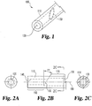
- FIG. 1 illustrates one example of a device 100 for sampling body fluid (not shown), comprising a main body 110 defining a capillary channel 120.
- the capillary channel 120 is preferably dimensioned to draw a body fluid into the capillary channel 120 through capillary action.
- the capillary channel 120 is further dimensioned to form an angled counterbore 130.
- the device 100 shown in FIG. 1 is cylindrical with an annular cross-section.
- FIGS. 2A, 2B and 2C further illustrates the example of FIG. 1 .
- the device, or apparatus, 100 comprises a body 110 defining a capillary channel 120 having a first region 140 and a second region 150 and a proximal portion 160 and a distal portion 170.
- the second region 150 of the capillary channel 120 defines a counterbore 130 ending in a surface non-normal to the longitudinal axis 180 of the capillary channel 120 by angle ⁇ .
- FIG. 3 illustrates the device 100 positioned above a drop of body fluid 310 issuing from an incision 305 in body tissue 300.
- the body fluid 310 may be produced by puncturing the body tissue 300, or by any other means.
- FIG. 4 illustrates the device 100 lowered toward the body tissue 300 until the proximal portion 160 of the capillary channel 120 is in fluid communication with the body fluid 310.
- the body fluid 310 is then drawn into the capillary channel 120 by capillary action, as represented in FIGS. 4 and 5 .
- the body fluid 310 flows in the capillary channel 120 from the proximal portion 160 toward the distal portion 170.
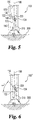
- the meniscus 320 of the body fluid 310 is biased radially asymmetrically about the centerline 180 toward one side of capillary channel 120, as shown in FIG. 5 .
- Capillary mechanics dictate that the step or offset created by the angled counterbore 130 causes the first region 140 to have an effectively stronger capillary attraction to body fluid 310 than the second region 150 when the body fluid 310 flows in the capillary channel 120 from the proximal portion 160 toward the distal portion 170.
- This difference in capillary attraction pulls or biases the meniscus 320 radially asymmetrically about the centerline 180, toward the first region 140 and away from the second region 150, thus biasing the body fluid 310 toward a first side 122 of the capillary channel 120, and away from a second side 124 of the capillary channel 120.
- FIG. 6 shows a device 100' that is similar to device 100, but has a counterbore 130' with an increased angle ⁇ '. As shown in FIG. 6 , increasing the angle from ⁇ to ⁇ ' tends to increase the bias of the meniscus 320 radially asymmetrically about the centerline 180, thus tending to increase the bias of the body fluid 310 toward a first side 122 of the capillary channel 120, and away from a second side 124 of the capillary channel 120.
- FIG. 7 shows the device 100' of FIG. 6 further including a testing element 700 disposed within a groove 710 in the main body 110' of the device 100".
- the testing element 700 is in spatial communication with body fluid 310 through one or more passageways 720, so that the testing element 700 may be used to test various aspects of the body fluid 310.
- Testing element 700 may be any testing means that interfaces with body fluid 310. Since the body fluid 310 tends to bias toward the first side 122 of the capillary channel 120, passageways 720 are shown formed in the first side 122 of the capillary channel 120.
- Passageways 720 are filled with body fluid 310, even though the adjacent portion of the capillary channel 120 is only partially filled with body fluid 310 due to the biasing effect described above.
- the device 100" is capable of communicating body fluid 310 to testing element 700 using less body fluid 310 than would be required without the capillary biasing effect described herein.
- FIG. 8 which is not an embodiment of the present invention illustrates another example device 100" configured to create a capillary biasing effect without requiring an angled counterbore 130 or any geometry such as a step or other shape in the capillary channel 120.
- the first side 122 of the capillary channel 120 includes a hydrophilic region 800.
- the hydrophilic region 800 is hydrophilic relative to one or more adjacent regions of the capillary channel 120, such as the second side 124.
- the hydrophilic region 800 need only be relatively hydrophilic; for instance, the hydrophilic region 800 may be defined by providing hydrophobic surrounding regions.
- a relatively hydrophilic region 800 may be created by forming portions of the capillary channel 120 from hydrophilic or hydrophobic materials, or by treating portions to be relatively hydrophilic or hydrophobic, for instance in the manners described in the above-incorporated patent applications.
- FIG. 9 which is not an embodiment of the present invention illustrates the device 100" of FIG. 8 positioned near body tissue 300 so that the proximal portion 160 of the capillary channel 120 is in fluid communication with a small drop of body fluid 310 issuing from an incision 305 in body tissue 300, the body fluid 310 being drawn into the capillary channel 120 by capillary action.
- the body fluid 310 reaches the relatively hydrophilic region 800, the body fluid 310 is disproportionately attracted to the hydrophilic region 800.
- This difference in capillary attraction pulls or biases the meniscus 320 radially asymmetrically about the centerline 180, thus biasing the body fluid 310 toward the relatively hydrophilic region 800 of the first side 122 of the capillary channel 120, and away from the relatively hydrophobic second side 124 of the capillary channel 120.
- FIG. 10 which is not an embodiment of the present invention shows the device 100" of FIG. 9 further including a testing element 700 disposed within a groove 710 in the main body 110" of the device 100".
- the testing element 700 is in spatial communication with body fluid 310 through one or more passageways 720, so that the testing element 700 may be used to test various aspects of the body fluid 310, as set forth above. Since the body fluid 310 tends to bias toward the hydrophilic region 800 on the first side 122 of the capillary channel 120, passageways 720 are shown formed in the first side 122 of the capillary channel 120. Passageways 720 are filled with body fluid 310, even though the adjacent portion of the capillary channel 120 is only partially filled with body fluid 310 due to the biasing effect described above. Thus, the device 100" is capable of communicating body fluid 310 to testing element 700 using less body fluid 310 than would be required without the capillary biasing effect described herein.
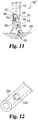
- FIG. 11 shows a device 100''' including by way of example both an angled counterbore 130 and a relatively hydrophilic region 800 in the capillary channel 120, and further including an integrated lancet 1100 for forming the incision 305.
- the integrated lancet 1100 may be used in conjunction with devices incorporating the capillary biasing effect described herein.
- devices including an integrated lancet 1100 can include any or all of the structure set forth in the above-incorporated patent applications.
- an angled counterbore 130 works in conjunction with a relatively hydrophilic region 800 to bias body fluid 310 toward testing element 700 using less body fluid 310 than would be required without the capillary biasing effect described herein.
- FIG. 12 illustrates a capillary tube 1200 according to another example, not forming part of the present invention.
- the capillary tube 1200 has a stepped-end counterbore 1202 for biasing the fluid in a specified direction inside the capillary tube.
- a plurality of sites on a testing device might be used for testing the same or different characteristics of the body fluid. Those sites might be spaced around the circumference of the device at approximately the same distance from the proximal end, or they might be situated at different distances from the proximal end. They may be on the same side of the device, opposite sides of the device, or in some other relative configuration.
- test sites including for example optical, magnetic, and chemical tests as would occur to one skilled in the art given the disclosure herein.
Description
- The present invention generally relates to the medical field, and more specifically, but not exclusively, relates to the sampling of bodily fluids.
- The acquisition and testing of body fluids is useful for many purposes, and continues to be of importance for use in medical diagnosis and treatment, and in other diverse applications, In the medical field, it is desirable for lay operators to perform tests routinely, quickly and accurately outside of a laboratory setting, with rapid results and a read-out of the resulting test information. Testing can be performed on various body fluids, and for certain applications, it is particularly related to testing of blood and/or interstitial fluid. Such fluids can be tested for a variety of characteristics of the fluid or analytes contained in the fluid, in order to identify medical conditions, determine therapeutic responses, assess progress of treatments and the like.
- A common medical test is the measurement of blood glucose levels. The glucose level can be determined directly by analysis of the blood, or indirectly by analysis of other fluids, such as interstitial fluid. Diabetics are generally instructed to measure their glucose levels several times a day, depending on the nature and severity of their diabetes. Based upon observed patterns in the measurement of glucose levels, the patient and physician can determine the appropriate level of insulin to be administered, also taking into account such issues as diet, exercise and other factors.
- In testing for the presence of analytes such as glucose in a body fluid, test systems are commonly used which take advantage of oxidation/reduction reaction, which occurs using an oxidase/peroxidase detection chemistry. The testing reagent is exposed to a sample of the body fluid for a suitable period of time, and there is a color change if analyte (glucose) is present. Typically, the intensity of the change is proportional to the concentration of analyte in the sample. The color of the reagent is then compared to a known standard, which enables one to determine the amount of analyte present in the sample. This determination can be made, for example, by visual check or by an instrument, such as a spectrophotometer at a selected wave length, or a blood glucose meter. Electrochemical and other systems are also well known for testing body fluids for properties of constituents. Typically, a fingertip or some other body location of a patient is lanced with a lancet in order to obtain a body fluid sample.
- Although fingertips generally provide an ample supply of blood, repeated lancing of fingertips can be quite painful due to the high concentration of nerve endings in the fingertips. Therefore, there has been a trend towards sampling fluids from alternate sites on the body, where the nerve concentrations are lower, such as the forearm. As should be appreciated, since alternate sites have lower nerve concentrations, the patient experiences less pain when lancing the alternate site. However, these alternate sites usually produce less fluid as compared to fingertips. Consequently, it has been a goal to reduce the amount of fluid needed for a successful test. To achieve this goal, it is desirable to ensure that as much fluid as possible is transported from the incision to the test area so as to minimize waste.
- Thus, there remains a need for improvement in this field.
-
WO 02/100277 A1 US 2002/0049390 A1 andEP 0 280 347 A1 disclose devices for sampling body fluids. These devices use capillary spaces or capillary passageways to take up and transport body fluid samples. -
-
FIG. 1 is an isometric view of a portion of an example apparatus according to the present invention. -
FIG. 2A is an end view of the apparatus ofFIG. 1 . -
FIG. 2B is a side view of the apparatus ofFIG. 1 . -
FIG. 2C is a cross-sectional view taken alongline 2C-2C ofFIG. 2B . -
FIG. 3 is a side view of the apparatus ofFIG. 1 disposed above body fluid on a tissue surface. -
FIG. 4 is a side view illustrating the apparatus ofFIG. 1 displaying the initial capillary action. -
FIG. 5 is a side view illustrating the apparatus ofFIG. 1 displaying biased capillary action. -
FIG. 6 is a side view of a portion of an alternative example apparatus according to the present invention displaying another form of biased capillary action. -
FIG. 7 is a side view of the apparatus ofFIG. 6 illustrating a test strip disposed within a groove in the apparatus. -
FIG. 8 is a side view of a portion of another alternative example apparatus not forming part of the present invention. -
FIG. 9 is a side view of the apparatus ofFIG. 8 displaying another form of biased capillary action. -
FIG. 10 is a side view of the apparatus ofFIG. 8 illustrating a test strip disposed within a groove in the apparatus. -
FIG. 11 is a side view of a portion of yet another alternative example apparatus according to the present invention. -
FIG. 12 is an isometric view of a portion of another example apparatus not forming part of the present invention. - Provided below is a written description of examples embodying the invention and examples of making and using the same. The scope of the invention is not limited to these examples, but rather is defined solely by the numbered claims that appear at the end of this document, and the invention includes alterations, modifications, and further applications that fall within the claims. The written description uses full, clear, concise, and exact terms to enable any person skilled in the art to which the invention pertains to make and use the invention. The best mode contemplated by the inventor of carrying out the invention is also set forth herein.
- The present invention generally concerns a sampling device that is configured to bias the flow of body fluid in the device so as to reduce the amount of fluid needed for sampling. In one embodiment, the device has a capillary channel that is structured to bias a miniscus of the fluid in a radially asymmetric manner. Specifically, the capillary channel has an angled counter bore that biases the meniscus of the fluid in a radial asymmetric manner. In another example, not forming part of the claimed invention, the capillary channel includes hydrophobic and hydrophillic portions that bias the flow of fluid.
-
FIG. 1 illustrates one example of adevice 100 for sampling body fluid (not shown), comprising amain body 110 defining acapillary channel 120. Thecapillary channel 120 is preferably dimensioned to draw a body fluid into thecapillary channel 120 through capillary action. Thecapillary channel 120 is further dimensioned to form anangled counterbore 130. - The
device 100 shown inFIG. 1 is cylindrical with an annular cross-section. -
Device 100 may comprise any material and may be made by any means.FIGS. 2A, 2B and 2C further illustrates the example ofFIG. 1 . The device, or apparatus, 100 comprises abody 110 defining acapillary channel 120 having afirst region 140 and asecond region 150 and aproximal portion 160 and adistal portion 170. In the example shown inFIGS. 1-5 , thesecond region 150 of thecapillary channel 120 defines acounterbore 130 ending in a surface non-normal to thelongitudinal axis 180 of thecapillary channel 120 by angle α. -
FIG. 3 illustrates thedevice 100 positioned above a drop ofbody fluid 310 issuing from anincision 305 inbody tissue 300. Thebody fluid 310 may be produced by puncturing thebody tissue 300, or by any other means.FIG. 4 illustrates thedevice 100 lowered toward thebody tissue 300 until theproximal portion 160 of thecapillary channel 120 is in fluid communication with thebody fluid 310. Thebody fluid 310 is then drawn into thecapillary channel 120 by capillary action, as represented inFIGS. 4 and5 . As shown inFIGS. 4 and5 , thebody fluid 310 flows in thecapillary channel 120 from theproximal portion 160 toward thedistal portion 170. However, when thebody fluid 310 reaches theangled counterbore 130, themeniscus 320 of thebody fluid 310 is biased radially asymmetrically about thecenterline 180 toward one side ofcapillary channel 120, as shown inFIG. 5 . - Capillary mechanics dictate that the step or offset created by the
angled counterbore 130 causes thefirst region 140 to have an effectively stronger capillary attraction tobody fluid 310 than thesecond region 150 when thebody fluid 310 flows in thecapillary channel 120 from theproximal portion 160 toward thedistal portion 170. This difference in capillary attraction pulls or biases themeniscus 320 radially asymmetrically about thecenterline 180, toward thefirst region 140 and away from thesecond region 150, thus biasing thebody fluid 310 toward afirst side 122 of thecapillary channel 120, and away from asecond side 124 of thecapillary channel 120. Subject to the materials and dimensions used indevice 100 and their interaction with aparticular body fluid 310, increasing the angle α tends to increasingly bias thebody fluid 310 toward afirst side 122 of thecapillary channel 120, and away from asecond side 124 of thecapillary channel 120. -
FIG. 6 shows a device 100' that is similar todevice 100, but has a counterbore 130' with an increased angle α'. As shown inFIG. 6 , increasing the angle from α to α' tends to increase the bias of themeniscus 320 radially asymmetrically about thecenterline 180, thus tending to increase the bias of thebody fluid 310 toward afirst side 122 of thecapillary channel 120, and away from asecond side 124 of thecapillary channel 120. -
FIG. 7 shows the device 100' ofFIG. 6 further including atesting element 700 disposed within agroove 710 in the main body 110' of thedevice 100". Whenbody fluid 310 has moved upfirst side 122, as shown, thetesting element 700 is in spatial communication withbody fluid 310 through one ormore passageways 720, so that thetesting element 700 may be used to test various aspects of thebody fluid 310.Testing element 700 may be any testing means that interfaces withbody fluid 310. Since thebody fluid 310 tends to bias toward thefirst side 122 of thecapillary channel 120,passageways 720 are shown formed in thefirst side 122 of thecapillary channel 120.Passageways 720 are filled withbody fluid 310, even though the adjacent portion of thecapillary channel 120 is only partially filled withbody fluid 310 due to the biasing effect described above. Thus, thedevice 100" is capable of communicatingbody fluid 310 totesting element 700 usingless body fluid 310 than would be required without the capillary biasing effect described herein. -
FIG. 8 which is not an embodiment of the present invention illustrates anotherexample device 100" configured to create a capillary biasing effect without requiring anangled counterbore 130 or any geometry such as a step or other shape in thecapillary channel 120. Instead, thefirst side 122 of thecapillary channel 120 includes ahydrophilic region 800. Thehydrophilic region 800 is hydrophilic relative to one or more adjacent regions of thecapillary channel 120, such as thesecond side 124. Thehydrophilic region 800 need only be relatively hydrophilic; for instance, thehydrophilic region 800 may be defined by providing hydrophobic surrounding regions. A relativelyhydrophilic region 800 may be created by forming portions of thecapillary channel 120 from hydrophilic or hydrophobic materials, or by treating portions to be relatively hydrophilic or hydrophobic, for instance in the manners described in the above-incorporated patent applications. -
FIG. 9 which is not an embodiment of the present invention illustrates thedevice 100" ofFIG. 8 positioned nearbody tissue 300 so that theproximal portion 160 of thecapillary channel 120 is in fluid communication with a small drop ofbody fluid 310 issuing from anincision 305 inbody tissue 300, thebody fluid 310 being drawn into thecapillary channel 120 by capillary action. When thebody fluid 310 reaches the relativelyhydrophilic region 800, thebody fluid 310 is disproportionately attracted to thehydrophilic region 800. This difference in capillary attraction pulls or biases themeniscus 320 radially asymmetrically about thecenterline 180, thus biasing thebody fluid 310 toward the relativelyhydrophilic region 800 of thefirst side 122 of thecapillary channel 120, and away from the relatively hydrophobicsecond side 124 of thecapillary channel 120. -
FIG. 10 which is not an embodiment of the present invention shows thedevice 100" ofFIG. 9 further including atesting element 700 disposed within agroove 710 in themain body 110" of thedevice 100". Thetesting element 700 is in spatial communication withbody fluid 310 through one ormore passageways 720, so that thetesting element 700 may be used to test various aspects of thebody fluid 310, as set forth above. Since thebody fluid 310 tends to bias toward thehydrophilic region 800 on thefirst side 122 of thecapillary channel 120,passageways 720 are shown formed in thefirst side 122 of thecapillary channel 120.Passageways 720 are filled withbody fluid 310, even though the adjacent portion of thecapillary channel 120 is only partially filled withbody fluid 310 due to the biasing effect described above. Thus, thedevice 100" is capable of communicatingbody fluid 310 totesting element 700 usingless body fluid 310 than would be required without the capillary biasing effect described herein. -
FIG. 11 shows a device 100''' including by way of example both anangled counterbore 130 and a relativelyhydrophilic region 800 in thecapillary channel 120, and further including anintegrated lancet 1100 for forming theincision 305. Theintegrated lancet 1100, or any other structure, may be used in conjunction with devices incorporating the capillary biasing effect described herein. For instance, devices including anintegrated lancet 1100 can include any or all of the structure set forth in the above-incorporated patent applications. In this example, anangled counterbore 130 works in conjunction with a relativelyhydrophilic region 800 to biasbody fluid 310 towardtesting element 700 usingless body fluid 310 than would be required without the capillary biasing effect described herein. -
FIG. 12 illustrates acapillary tube 1200 according to another example, not forming part of the present invention. In the illustrated example, thecapillary tube 1200 has a stepped-end counterbore 1202 for biasing the fluid in a specified direction inside the capillary tube. A plurality of sites on a testing device might be used for testing the same or different characteristics of the body fluid. Those sites might be spaced around the circumference of the device at approximately the same distance from the proximal end, or they might be situated at different distances from the proximal end. They may be on the same side of the device, opposite sides of the device, or in some other relative configuration. - Further, various tests may be implemented at the one or more test sites, including for example optical, magnetic, and chemical tests as would occur to one skilled in the art given the disclosure herein.
Claims (4)
- A cylindrical device (100) with an annular cross-section for sampling body fluid (310), said device (100) comprising a main body (110) that defines a capillary channel (120), wherein:said capillary channel (120) is dimensioned to draw a body fluid (310) into said capillary channel (120) by capillary action;said body fluid (310) defines a meniscus (320) when said body fluid (310) is drawn into said capillary channel (120);characterized in thatsaid capillary channel (120) has an angled counterbore (130)to bias said meniscus (320) in a radially asymmetric manner toward a testing element (700) in spatial communication with said fluid (310) when said body fluid (310) is drawn into said capillary channel (120).
- The device (100) of claim 1 wherein said testing element (700) comprises a test strip.
- The device (100) of claim 2 wherein said test strip comprises a membrane.
- The device (100) of claim 2 wherein said test strip is mounted in a groove (710) defined in said device (100).
Applications Claiming Priority (3)
| Application Number | Priority Date | Filing Date | Title |
|---|---|---|---|
| US43633102P | 2002-12-24 | 2002-12-24 | |
| US436331P | 2002-12-24 | ||
| PCT/US2003/039323 WO2004060160A1 (en) | 2002-12-24 | 2003-12-10 | A sampling device utilizing biased capillary action |
Publications (2)
| Publication Number | Publication Date |
|---|---|
| EP1578270A1 EP1578270A1 (en) | 2005-09-28 |
| EP1578270B1 true EP1578270B1 (en) | 2018-08-01 |
Family
ID=32713063
Family Applications (1)
| Application Number | Title | Priority Date | Filing Date |
|---|---|---|---|
| EP03796923.5A Expired - Lifetime EP1578270B1 (en) | 2002-12-24 | 2003-12-10 | A sampling device utilizing biased capillary action |
Country Status (4)
| Country | Link |
|---|---|
| US (3) | US20040122339A1 (en) |
| EP (1) | EP1578270B1 (en) |
| AU (1) | AU2003297853A1 (en) |
| WO (1) | WO2004060160A1 (en) |
Families Citing this family (77)
| Publication number | Priority date | Publication date | Assignee | Title |
|---|---|---|---|---|
| US6036924A (en) | 1997-12-04 | 2000-03-14 | Hewlett-Packard Company | Cassette of lancet cartridges for sampling blood |
| US6391005B1 (en) | 1998-03-30 | 2002-05-21 | Agilent Technologies, Inc. | Apparatus and method for penetration with shaft having a sensor for sensing penetration depth |
| US8641644B2 (en) | 2000-11-21 | 2014-02-04 | Sanofi-Aventis Deutschland Gmbh | Blood testing apparatus having a rotatable cartridge with multiple lancing elements and testing means |
| US7025774B2 (en) | 2001-06-12 | 2006-04-11 | Pelikan Technologies, Inc. | Tissue penetration device |
| US7981056B2 (en) | 2002-04-19 | 2011-07-19 | Pelikan Technologies, Inc. | Methods and apparatus for lancet actuation |
| US9795747B2 (en) | 2010-06-02 | 2017-10-24 | Sanofi-Aventis Deutschland Gmbh | Methods and apparatus for lancet actuation |
| US9226699B2 (en) | 2002-04-19 | 2016-01-05 | Sanofi-Aventis Deutschland Gmbh | Body fluid sampling module with a continuous compression tissue interface surface |
| US8337419B2 (en) | 2002-04-19 | 2012-12-25 | Sanofi-Aventis Deutschland Gmbh | Tissue penetration device |
| EP1404234B1 (en) | 2001-06-12 | 2011-02-09 | Pelikan Technologies Inc. | Apparatus for improving success rate of blood yield from a fingerstick |
| DE60238119D1 (en) | 2001-06-12 | 2010-12-09 | Pelikan Technologies Inc | ELECTRIC ACTUATOR ELEMENT FOR A LANZETTE |
| JP4272051B2 (en) | 2001-06-12 | 2009-06-03 | ペリカン テクノロジーズ インコーポレイテッド | Blood sampling apparatus and method |
| US9427532B2 (en) | 2001-06-12 | 2016-08-30 | Sanofi-Aventis Deutschland Gmbh | Tissue penetration device |
| ES2336081T3 (en) | 2001-06-12 | 2010-04-08 | Pelikan Technologies Inc. | SELF-OPTIMIZATION PUNCTURE DEVICE WITH MEANS OF ADAPTATION TO TEMPORARY VARIATIONS IN CUTANEOUS PROPERTIES. |
| WO2002100254A2 (en) | 2001-06-12 | 2002-12-19 | Pelikan Technologies, Inc. | Method and apparatus for lancet launching device integrated onto a blood-sampling cartridge |
| US7004928B2 (en) | 2002-02-08 | 2006-02-28 | Rosedale Medical, Inc. | Autonomous, ambulatory analyte monitor or drug delivery device |
| US7331931B2 (en) | 2002-04-19 | 2008-02-19 | Pelikan Technologies, Inc. | Method and apparatus for penetrating tissue |
| US7892183B2 (en) | 2002-04-19 | 2011-02-22 | Pelikan Technologies, Inc. | Method and apparatus for body fluid sampling and analyte sensing |
| US9314194B2 (en) | 2002-04-19 | 2016-04-19 | Sanofi-Aventis Deutschland Gmbh | Tissue penetration device |
| US9795334B2 (en) | 2002-04-19 | 2017-10-24 | Sanofi-Aventis Deutschland Gmbh | Method and apparatus for penetrating tissue |
| US7674232B2 (en) | 2002-04-19 | 2010-03-09 | Pelikan Technologies, Inc. | Method and apparatus for penetrating tissue |
| US7976476B2 (en) | 2002-04-19 | 2011-07-12 | Pelikan Technologies, Inc. | Device and method for variable speed lancet |
| US7708701B2 (en) | 2002-04-19 | 2010-05-04 | Pelikan Technologies, Inc. | Method and apparatus for a multi-use body fluid sampling device |
| US7901362B2 (en) | 2002-04-19 | 2011-03-08 | Pelikan Technologies, Inc. | Method and apparatus for penetrating tissue |
| US8360992B2 (en) | 2002-04-19 | 2013-01-29 | Sanofi-Aventis Deutschland Gmbh | Method and apparatus for penetrating tissue |
| US8267870B2 (en) | 2002-04-19 | 2012-09-18 | Sanofi-Aventis Deutschland Gmbh | Method and apparatus for body fluid sampling with hybrid actuation |
| US8579831B2 (en) | 2002-04-19 | 2013-11-12 | Sanofi-Aventis Deutschland Gmbh | Method and apparatus for penetrating tissue |
| US7297122B2 (en) | 2002-04-19 | 2007-11-20 | Pelikan Technologies, Inc. | Method and apparatus for penetrating tissue |
| US7648468B2 (en) | 2002-04-19 | 2010-01-19 | Pelikon Technologies, Inc. | Method and apparatus for penetrating tissue |
| US8702624B2 (en) | 2006-09-29 | 2014-04-22 | Sanofi-Aventis Deutschland Gmbh | Analyte measurement device with a single shot actuator |
| US7909778B2 (en) | 2002-04-19 | 2011-03-22 | Pelikan Technologies, Inc. | Method and apparatus for penetrating tissue |
| US7229458B2 (en) | 2002-04-19 | 2007-06-12 | Pelikan Technologies, Inc. | Method and apparatus for penetrating tissue |
| US7232451B2 (en) | 2002-04-19 | 2007-06-19 | Pelikan Technologies, Inc. | Method and apparatus for penetrating tissue |
| US7547287B2 (en) | 2002-04-19 | 2009-06-16 | Pelikan Technologies, Inc. | Method and apparatus for penetrating tissue |
| US7717863B2 (en) | 2002-04-19 | 2010-05-18 | Pelikan Technologies, Inc. | Method and apparatus for penetrating tissue |
| US8372016B2 (en) | 2002-04-19 | 2013-02-12 | Sanofi-Aventis Deutschland Gmbh | Method and apparatus for body fluid sampling and analyte sensing |
| US7175642B2 (en) | 2002-04-19 | 2007-02-13 | Pelikan Technologies, Inc. | Methods and apparatus for lancet actuation |
| US8784335B2 (en) | 2002-04-19 | 2014-07-22 | Sanofi-Aventis Deutschland Gmbh | Body fluid sampling device with a capacitive sensor |
| US7371247B2 (en) | 2002-04-19 | 2008-05-13 | Pelikan Technologies, Inc | Method and apparatus for penetrating tissue |
| US7291117B2 (en) | 2002-04-19 | 2007-11-06 | Pelikan Technologies, Inc. | Method and apparatus for penetrating tissue |
| US8221334B2 (en) | 2002-04-19 | 2012-07-17 | Sanofi-Aventis Deutschland Gmbh | Method and apparatus for penetrating tissue |
| US9248267B2 (en) | 2002-04-19 | 2016-02-02 | Sanofi-Aventis Deustchland Gmbh | Tissue penetration device |
| US7491178B2 (en) | 2002-04-19 | 2009-02-17 | Pelikan Technologies, Inc. | Method and apparatus for penetrating tissue |
| US8574895B2 (en) | 2002-12-30 | 2013-11-05 | Sanofi-Aventis Deutschland Gmbh | Method and apparatus using optical techniques to measure analyte levels |
| US7052652B2 (en) | 2003-03-24 | 2006-05-30 | Rosedale Medical, Inc. | Analyte concentration detection devices and methods |
| ATE476137T1 (en) | 2003-05-30 | 2010-08-15 | Pelikan Technologies Inc | METHOD AND DEVICE FOR INJECTING LIQUID |
| DK1633235T3 (en) | 2003-06-06 | 2014-08-18 | Sanofi Aventis Deutschland | Apparatus for sampling body fluid and detecting analyte |
| WO2006001797A1 (en) | 2004-06-14 | 2006-01-05 | Pelikan Technologies, Inc. | Low pain penetrating |
| EP1671096A4 (en) | 2003-09-29 | 2009-09-16 | Pelikan Technologies Inc | Method and apparatus for an improved sample capture device |
| EP1680014A4 (en) | 2003-10-14 | 2009-01-21 | Pelikan Technologies Inc | Method and apparatus for a variable user interface |
| EP1706026B1 (en) | 2003-12-31 | 2017-03-01 | Sanofi-Aventis Deutschland GmbH | Method and apparatus for improving fluidic flow and sample capture |
| US7822454B1 (en) | 2005-01-03 | 2010-10-26 | Pelikan Technologies, Inc. | Fluid sampling device with improved analyte detecting member configuration |
| US8828203B2 (en) | 2004-05-20 | 2014-09-09 | Sanofi-Aventis Deutschland Gmbh | Printable hydrogels for biosensors |
| US9775553B2 (en) | 2004-06-03 | 2017-10-03 | Sanofi-Aventis Deutschland Gmbh | Method and apparatus for a fluid sampling device |
| WO2005120365A1 (en) | 2004-06-03 | 2005-12-22 | Pelikan Technologies, Inc. | Method and apparatus for a fluid sampling device |
| US7604604B2 (en) | 2004-09-09 | 2009-10-20 | Roche Diagnostics Operations, Inc. | Device for sampling bodily fluids |
| US7645241B2 (en) * | 2004-09-09 | 2010-01-12 | Roche Diagnostics Operations, Inc. | Device for sampling bodily fluids |
| GB0420256D0 (en) | 2004-09-13 | 2004-10-13 | Cassells John M | Method and apparatus for sampling and analysis of fluids |
| US8652831B2 (en) | 2004-12-30 | 2014-02-18 | Sanofi-Aventis Deutschland Gmbh | Method and apparatus for analyte measurement test time |
| US20060281187A1 (en) | 2005-06-13 | 2006-12-14 | Rosedale Medical, Inc. | Analyte detection devices and methods with hematocrit/volume correction and feedback control |
| US8801631B2 (en) | 2005-09-30 | 2014-08-12 | Intuity Medical, Inc. | Devices and methods for facilitating fluid transport |
| US8382681B2 (en) | 2005-09-30 | 2013-02-26 | Intuity Medical, Inc. | Fully integrated wearable or handheld monitor |
| GB0605003D0 (en) * | 2006-03-13 | 2006-04-19 | Microsample Ltd | Method and apparatus for piercing the skin and delivery or collection of liquids |
| WO2009126900A1 (en) | 2008-04-11 | 2009-10-15 | Pelikan Technologies, Inc. | Method and apparatus for analyte detecting device |
| CA2725264C (en) | 2008-05-30 | 2017-06-20 | Intuity Medical, Inc. | Body fluid sampling device -- sampling site interface |
| US9636051B2 (en) | 2008-06-06 | 2017-05-02 | Intuity Medical, Inc. | Detection meter and mode of operation |
| EP2299904B1 (en) | 2008-06-06 | 2019-09-11 | Intuity Medical, Inc. | Medical measurement method |
| US9375169B2 (en) | 2009-01-30 | 2016-06-28 | Sanofi-Aventis Deutschland Gmbh | Cam drive for managing disposable penetrating member actions with a single motor and motor and control system |
| WO2011065981A1 (en) | 2009-11-30 | 2011-06-03 | Intuity Medical, Inc. | Calibration material delivery devices and methods |
| US8965476B2 (en) | 2010-04-16 | 2015-02-24 | Sanofi-Aventis Deutschland Gmbh | Tissue penetration device |
| EP2384699B1 (en) * | 2010-05-06 | 2012-12-12 | Roche Diagnostics GmbH | Lancet cartridge and method for its production |
| US10330667B2 (en) | 2010-06-25 | 2019-06-25 | Intuity Medical, Inc. | Analyte monitoring methods and systems |
| GB2529972B (en) * | 2010-06-30 | 2016-07-13 | Schlumberger Holdings | Identification of neutron capture from a pulsed neutron logging tool |
| JP6223337B2 (en) | 2011-08-03 | 2017-11-08 | インテュイティ メディカル インコーポレイテッド | Body fluid extraction measuring instrument |
| WO2014205412A1 (en) | 2013-06-21 | 2014-12-24 | Intuity Medical, Inc. | Analyte monitoring system with audible feedback |
| US9480981B2 (en) | 2014-07-25 | 2016-11-01 | General Electric Company | Sample collection and transfer device |
| US9901922B2 (en) | 2014-07-25 | 2018-02-27 | General Electric Company | Sample collection and transfer device |
| JP2023162456A (en) * | 2020-09-03 | 2023-11-09 | セルスペクト株式会社 | Liquid sampling tool, method for manufacturing the same, and test kit |
Family Cites Families (47)
| Publication number | Priority date | Publication date | Assignee | Title |
|---|---|---|---|---|
| CH522395A (en) * | 1968-07-26 | 1972-05-15 | Micromedic Systems Inc | Test tube intended for percutaneous and digital blood sampling |
| FR2437668A1 (en) * | 1978-09-29 | 1980-04-25 | Thomson Csf | PROTECTED OPTICAL DISC |
| US4360016A (en) * | 1980-07-01 | 1982-11-23 | Transidyne General Corp. | Blood collecting device |
| US4416279A (en) * | 1981-06-19 | 1983-11-22 | Lindner James A | Capillary blood sampling device |
| US4503856A (en) * | 1981-06-29 | 1985-03-12 | Sherwood Medical Company | Lancet injector |
| US4517978A (en) * | 1983-01-13 | 1985-05-21 | Levin Paul D | Blood sampling instrument |
| US4858507A (en) * | 1983-04-20 | 1989-08-22 | Esselte Pendaflex Corporation | Mat board cutter with adjustable cutter-carrying body |
| EP0166574A3 (en) | 1984-06-28 | 1987-06-16 | Mitchell P. Dombrowski, M.D. | Fetal blood sampling instrument |
| US4627445A (en) * | 1985-04-08 | 1986-12-09 | Garid, Inc. | Glucose medical monitoring system |
| US4653513A (en) | 1985-08-09 | 1987-03-31 | Dombrowski Mitchell P | Blood sampler |
| NL8700277A (en) * | 1987-02-05 | 1988-09-01 | Livestock Control Holding | DEVICE FOR VACUUM AND DROPPING A LIQUID. |
| GB8710470D0 (en) * | 1987-05-01 | 1987-06-03 | Mumford Ltd Owen | Blood sampling devices |
| US4858607A (en) * | 1987-10-16 | 1989-08-22 | Pavel Jordan & Associates | Plastic device for injection and obtaining blood samples |
| AU2944889A (en) * | 1988-01-14 | 1989-08-11 | Novo Nordisk A/S | Apparatus for determination of the coagulation time of a blood sample |
| US4924879A (en) * | 1988-10-07 | 1990-05-15 | Brien Walter J O | Blood lancet device |
| US4920977A (en) * | 1988-10-25 | 1990-05-01 | Becton, Dickinson And Company | Blood collection assembly with lancet and microcollection tube |
| US5139489A (en) * | 1991-01-07 | 1992-08-18 | Smiths Industries Medical Systems, Inc. | Needle protection device |
| US5230864A (en) * | 1991-04-10 | 1993-07-27 | Eastman Kodak Company | Gravity assisted collection device |
| US5402798A (en) * | 1991-07-18 | 1995-04-04 | Swierczek; Remi | Disposable skin perforator and blood testing device |
| JP2572823Y2 (en) * | 1992-02-13 | 1998-05-25 | 株式会社アドバンス | Simple blood sampler |
| DE4212315A1 (en) * | 1992-04-13 | 1993-10-14 | Boehringer Mannheim Gmbh | Blood lancet device for drawing blood for diagnostic purposes |
| US5318583A (en) | 1992-05-05 | 1994-06-07 | Ryder International Corporation | Lancet actuator mechanism |
| US5322609A (en) * | 1992-09-24 | 1994-06-21 | Becton, Dickinson And Company | Device for detecting electrolytes in liquid samples |
| JP2630197B2 (en) * | 1993-04-28 | 1997-07-16 | 株式会社ニッショー | Blood suction device |
| JP3304342B2 (en) | 1993-12-03 | 2002-07-22 | ニプロ株式会社 | Blood suction device |
| US5674236A (en) * | 1996-04-30 | 1997-10-07 | Medtronic, Inc. | Lancet for capillary puncture blood samples |
| JP3802568B2 (en) | 1996-05-17 | 2006-07-26 | ロシェ ダイアグノスティックス オペレイションズ インコーポレイテッド | Body fluid sampling device |
| US5879311A (en) * | 1996-05-17 | 1999-03-09 | Mercury Diagnostics, Inc. | Body fluid sampling device and methods of use |
| ES2121565B1 (en) * | 1996-05-17 | 2000-12-16 | Mercury Diagnostics Inc | DISPOSABLE ITEM FOR USE IN A BODY FLUID SAMPLING DEVICE. |
| US6332871B1 (en) * | 1996-05-17 | 2001-12-25 | Amira Medical | Blood and interstitial fluid sampling device |
| US6146361A (en) * | 1996-09-26 | 2000-11-14 | Becton Dickinson And Company | Medication delivery pen having a 31 gauge needle |
| US6071251A (en) | 1996-12-06 | 2000-06-06 | Abbott Laboratories | Method and apparatus for obtaining blood for diagnostic tests |
| US6086545A (en) | 1998-04-28 | 2000-07-11 | Amira Medical | Methods and apparatus for suctioning and pumping body fluid from an incision |
| JP3398598B2 (en) * | 1998-06-10 | 2003-04-21 | 松下電器産業株式会社 | Substrate quantification method and analytical element and measuring device used for the method |
| WO2000040150A1 (en) | 1999-01-04 | 2000-07-13 | Terumo Kabushiki Kaisha | Assembly having lancet and means for collecting and detecting body fluid |
| US6368563B1 (en) * | 1999-03-12 | 2002-04-09 | Integ, Inc. | Collection well for body fluid tester |
| JP3985022B2 (en) * | 1999-11-08 | 2007-10-03 | アークレイ株式会社 | Body fluid measuring device and insertion body used by being inserted into the body fluid measuring device |
| US6375627B1 (en) * | 2000-03-02 | 2002-04-23 | Agilent Technologies, Inc. | Physiological fluid extraction with rapid analysis |
| US6612111B1 (en) * | 2000-03-27 | 2003-09-02 | Lifescan, Inc. | Method and device for sampling and analyzing interstitial fluid and whole blood samples |
| US6571651B1 (en) | 2000-03-27 | 2003-06-03 | Lifescan, Inc. | Method of preventing short sampling of a capillary or wicking fill device |
| CN1525834A (en) * | 2001-01-22 | 2004-09-01 | - | Lancet device having capillary action |
| DE60238814D1 (en) * | 2001-03-29 | 2011-02-17 | Lifescan Scotland Ltd | INTEGRATED BLOOD PROBE WITH TESTS |
| AU2002310362A1 (en) * | 2001-06-08 | 2002-12-23 | F. Hoffmann-La Roche Ag | Sampling devices and methods utilizing a stepped capillary passageway |
| JP3854967B2 (en) | 2001-06-08 | 2006-12-06 | エフ ホフマン−ラ ロッシュ アクチェン ゲゼルシャフト | Device for extruding body fluid from the incision |
| US20020188223A1 (en) * | 2001-06-08 | 2002-12-12 | Edward Perez | Devices and methods for the expression of bodily fluids from an incision |
| JP4272051B2 (en) | 2001-06-12 | 2009-06-03 | ペリカン テクノロジーズ インコーポレイテッド | Blood sampling apparatus and method |
| CA2458208A1 (en) | 2001-08-29 | 2003-03-13 | F. Hoffmann-La Roche Ag | Wicking methods and structures for use in sampling bodily fluids |
-
2003
- 2003-12-10 US US10/732,615 patent/US20040122339A1/en not_active Abandoned
- 2003-12-10 AU AU2003297853A patent/AU2003297853A1/en not_active Abandoned
- 2003-12-10 EP EP03796923.5A patent/EP1578270B1/en not_active Expired - Lifetime
- 2003-12-10 WO PCT/US2003/039323 patent/WO2004060160A1/en not_active Application Discontinuation
-
2010
- 2010-02-16 US US12/706,015 patent/US8083688B2/en not_active Expired - Fee Related
-
2011
- 2011-11-25 US US13/304,441 patent/US20120065545A1/en not_active Abandoned
Also Published As
| Publication number | Publication date |
|---|---|
| WO2004060160A1 (en) | 2004-07-22 |
| US8083688B2 (en) | 2011-12-27 |
| US20040122339A1 (en) | 2004-06-24 |
| US20100145228A1 (en) | 2010-06-10 |
| EP1578270A1 (en) | 2005-09-28 |
| AU2003297853A1 (en) | 2004-07-29 |
| US20120065545A1 (en) | 2012-03-15 |
Similar Documents
| Publication | Publication Date | Title |
|---|---|---|
| EP1578270B1 (en) | A sampling device utilizing biased capillary action | |
| US7244264B2 (en) | Dual blade lancing test strip | |
| US7604604B2 (en) | Device for sampling bodily fluids | |
| US7476202B2 (en) | Sampling devices and methods utilizing a horizontal capillary test strip | |
| US8419657B2 (en) | Device for sampling bodily fluids | |
| US7247144B2 (en) | Methods and apparatus for sampling and analyzing body fluid | |
| US9554741B2 (en) | Precision depth control lancing tip | |
| JP4365116B2 (en) | Puncture needle integrated minimal invasive optical format | |
| KR20030079958A (en) | Lancet device having capillary action | |
| JP2009509645A (en) | Apparatus and method for facilitating fluid transfer | |
| BRPI0508528B1 (en) | DEVICE FOR SAMPLING A BODY FLUID AND SYSTEM FOR ANALYSIS OF A BODY FLUID | |
| EP1399066B1 (en) | Devices for the expression of bodily fluids from an incision | |
| EP1399065B1 (en) | Sampling devices and methods utilizing a stepped capillary passageway | |
| WO2002100275A1 (en) | Sampling devices and methods for bodily fluids | |
| WO2007047812A2 (en) | Analyte-testing instruments having antimicrobial properties and methods of using the same |
Legal Events
| Date | Code | Title | Description |
|---|---|---|---|
| PUAI | Public reference made under article 153(3) epc to a published international application that has entered the european phase |
Free format text: ORIGINAL CODE: 0009012 |
|
| 17P | Request for examination filed |
Effective date: 20050725 |
|
| AK | Designated contracting states |
Kind code of ref document: A1 Designated state(s): AT BE BG CH CY CZ DE DK EE ES FI FR GB GR HU IE IT LI LU MC NL PT RO SE SI SK TR |
|
| AX | Request for extension of the european patent |
Extension state: AL LT LV MK |
|
| DAX | Request for extension of the european patent (deleted) | ||
| RAP1 | Party data changed (applicant data changed or rights of an application transferred) |
Owner name: ROCHE DIAGNOSTICS GMBH Owner name: F. HOFFMANN-LA ROCHE AG |
|
| 17Q | First examination report despatched |
Effective date: 20060630 |
|
| RAP1 | Party data changed (applicant data changed or rights of an application transferred) |
Owner name: ROCHE DIABETES CARE GMBH Owner name: F. HOFFMANN-LA ROCHE AG |
|
| GRAP | Despatch of communication of intention to grant a patent |
Free format text: ORIGINAL CODE: EPIDOSNIGR1 |
|
| STAA | Information on the status of an ep patent application or granted ep patent |
Free format text: STATUS: GRANT OF PATENT IS INTENDED |
|
| INTG | Intention to grant announced |
Effective date: 20171019 |
|
| GRAS | Grant fee paid |
Free format text: ORIGINAL CODE: EPIDOSNIGR3 |
|
| GRAA | (expected) grant |
Free format text: ORIGINAL CODE: 0009210 |
|
| STAA | Information on the status of an ep patent application or granted ep patent |
Free format text: STATUS: THE PATENT HAS BEEN GRANTED |
|
| AK | Designated contracting states |
Kind code of ref document: B1 Designated state(s): AT BE BG CH CY CZ DE DK EE ES FI FR GB GR HU IE IT LI LU MC NL PT RO SE SI SK TR |
|
| REG | Reference to a national code |
Ref country code: GB Ref legal event code: FG4D |
|
| REG | Reference to a national code |
Ref country code: CH Ref legal event code: EP Ref country code: AT Ref legal event code: REF Ref document number: 1023361 Country of ref document: AT Kind code of ref document: T Effective date: 20180815 |
|
| REG | Reference to a national code |
Ref country code: IE Ref legal event code: FG4D |
|
| REG | Reference to a national code |
Ref country code: DE Ref legal event code: R096 Ref document number: 60351368 Country of ref document: DE |
|
| REG | Reference to a national code |
Ref country code: NL Ref legal event code: MP Effective date: 20180801 |
|
| REG | Reference to a national code |
Ref country code: AT Ref legal event code: MK05 Ref document number: 1023361 Country of ref document: AT Kind code of ref document: T Effective date: 20180801 |
|
| PG25 | Lapsed in a contracting state [announced via postgrant information from national office to epo] |
Ref country code: NL Free format text: LAPSE BECAUSE OF FAILURE TO SUBMIT A TRANSLATION OF THE DESCRIPTION OR TO PAY THE FEE WITHIN THE PRESCRIBED TIME-LIMIT Effective date: 20180801 Ref country code: AT Free format text: LAPSE BECAUSE OF FAILURE TO SUBMIT A TRANSLATION OF THE DESCRIPTION OR TO PAY THE FEE WITHIN THE PRESCRIBED TIME-LIMIT Effective date: 20180801 Ref country code: GR Free format text: LAPSE BECAUSE OF FAILURE TO SUBMIT A TRANSLATION OF THE DESCRIPTION OR TO PAY THE FEE WITHIN THE PRESCRIBED TIME-LIMIT Effective date: 20181102 Ref country code: FI Free format text: LAPSE BECAUSE OF FAILURE TO SUBMIT A TRANSLATION OF THE DESCRIPTION OR TO PAY THE FEE WITHIN THE PRESCRIBED TIME-LIMIT Effective date: 20180801 Ref country code: SE Free format text: LAPSE BECAUSE OF FAILURE TO SUBMIT A TRANSLATION OF THE DESCRIPTION OR TO PAY THE FEE WITHIN THE PRESCRIBED TIME-LIMIT Effective date: 20180801 Ref country code: BG Free format text: LAPSE BECAUSE OF FAILURE TO SUBMIT A TRANSLATION OF THE DESCRIPTION OR TO PAY THE FEE WITHIN THE PRESCRIBED TIME-LIMIT Effective date: 20181101 |
|
| PG25 | Lapsed in a contracting state [announced via postgrant information from national office to epo] |
Ref country code: ES Free format text: LAPSE BECAUSE OF FAILURE TO SUBMIT A TRANSLATION OF THE DESCRIPTION OR TO PAY THE FEE WITHIN THE PRESCRIBED TIME-LIMIT Effective date: 20180801 |
|
| PG25 | Lapsed in a contracting state [announced via postgrant information from national office to epo] |
Ref country code: EE Free format text: LAPSE BECAUSE OF FAILURE TO SUBMIT A TRANSLATION OF THE DESCRIPTION OR TO PAY THE FEE WITHIN THE PRESCRIBED TIME-LIMIT Effective date: 20180801 Ref country code: CZ Free format text: LAPSE BECAUSE OF FAILURE TO SUBMIT A TRANSLATION OF THE DESCRIPTION OR TO PAY THE FEE WITHIN THE PRESCRIBED TIME-LIMIT Effective date: 20180801 Ref country code: RO Free format text: LAPSE BECAUSE OF FAILURE TO SUBMIT A TRANSLATION OF THE DESCRIPTION OR TO PAY THE FEE WITHIN THE PRESCRIBED TIME-LIMIT Effective date: 20180801 |
|
| REG | Reference to a national code |
Ref country code: DE Ref legal event code: R097 Ref document number: 60351368 Country of ref document: DE |
|
| PG25 | Lapsed in a contracting state [announced via postgrant information from national office to epo] |
Ref country code: SK Free format text: LAPSE BECAUSE OF FAILURE TO SUBMIT A TRANSLATION OF THE DESCRIPTION OR TO PAY THE FEE WITHIN THE PRESCRIBED TIME-LIMIT Effective date: 20180801 Ref country code: DK Free format text: LAPSE BECAUSE OF FAILURE TO SUBMIT A TRANSLATION OF THE DESCRIPTION OR TO PAY THE FEE WITHIN THE PRESCRIBED TIME-LIMIT Effective date: 20180801 |
|
| PLBE | No opposition filed within time limit |
Free format text: ORIGINAL CODE: 0009261 |
|
| STAA | Information on the status of an ep patent application or granted ep patent |
Free format text: STATUS: NO OPPOSITION FILED WITHIN TIME LIMIT |
|
| 26N | No opposition filed |
Effective date: 20190503 |
|
| REG | Reference to a national code |
Ref country code: CH Ref legal event code: PL |
|
| PG25 | Lapsed in a contracting state [announced via postgrant information from national office to epo] |
Ref country code: LU Free format text: LAPSE BECAUSE OF NON-PAYMENT OF DUE FEES Effective date: 20181210 Ref country code: SI Free format text: LAPSE BECAUSE OF FAILURE TO SUBMIT A TRANSLATION OF THE DESCRIPTION OR TO PAY THE FEE WITHIN THE PRESCRIBED TIME-LIMIT Effective date: 20180801 Ref country code: MC Free format text: LAPSE BECAUSE OF FAILURE TO SUBMIT A TRANSLATION OF THE DESCRIPTION OR TO PAY THE FEE WITHIN THE PRESCRIBED TIME-LIMIT Effective date: 20180801 |
|
| REG | Reference to a national code |
Ref country code: IE Ref legal event code: MM4A |
|
| REG | Reference to a national code |
Ref country code: BE Ref legal event code: MM Effective date: 20181231 |
|
| PG25 | Lapsed in a contracting state [announced via postgrant information from national office to epo] |
Ref country code: IE Free format text: LAPSE BECAUSE OF NON-PAYMENT OF DUE FEES Effective date: 20181210 |
|
| PG25 | Lapsed in a contracting state [announced via postgrant information from national office to epo] |
Ref country code: BE Free format text: LAPSE BECAUSE OF NON-PAYMENT OF DUE FEES Effective date: 20181231 |
|
| PG25 | Lapsed in a contracting state [announced via postgrant information from national office to epo] |
Ref country code: CH Free format text: LAPSE BECAUSE OF NON-PAYMENT OF DUE FEES Effective date: 20181231 Ref country code: LI Free format text: LAPSE BECAUSE OF NON-PAYMENT OF DUE FEES Effective date: 20181231 |
|
| PG25 | Lapsed in a contracting state [announced via postgrant information from national office to epo] |
Ref country code: TR Free format text: LAPSE BECAUSE OF FAILURE TO SUBMIT A TRANSLATION OF THE DESCRIPTION OR TO PAY THE FEE WITHIN THE PRESCRIBED TIME-LIMIT Effective date: 20180801 |
|
| PG25 | Lapsed in a contracting state [announced via postgrant information from national office to epo] |
Ref country code: PT Free format text: LAPSE BECAUSE OF FAILURE TO SUBMIT A TRANSLATION OF THE DESCRIPTION OR TO PAY THE FEE WITHIN THE PRESCRIBED TIME-LIMIT Effective date: 20180801 |
|
| PG25 | Lapsed in a contracting state [announced via postgrant information from national office to epo] |
Ref country code: HU Free format text: LAPSE BECAUSE OF FAILURE TO SUBMIT A TRANSLATION OF THE DESCRIPTION OR TO PAY THE FEE WITHIN THE PRESCRIBED TIME-LIMIT; INVALID AB INITIO Effective date: 20031210 Ref country code: CY Free format text: LAPSE BECAUSE OF FAILURE TO SUBMIT A TRANSLATION OF THE DESCRIPTION OR TO PAY THE FEE WITHIN THE PRESCRIBED TIME-LIMIT Effective date: 20180801 |
|
| PGFP | Annual fee paid to national office [announced via postgrant information from national office to epo] |
Ref country code: GB Payment date: 20201130 Year of fee payment: 18 Ref country code: FR Payment date: 20201119 Year of fee payment: 18 Ref country code: DE Payment date: 20201112 Year of fee payment: 18 |
|
| PGFP | Annual fee paid to national office [announced via postgrant information from national office to epo] |
Ref country code: IT Payment date: 20201222 Year of fee payment: 18 |
|
| REG | Reference to a national code |
Ref country code: DE Ref legal event code: R119 Ref document number: 60351368 Country of ref document: DE |
|
| GBPC | Gb: european patent ceased through non-payment of renewal fee |
Effective date: 20211210 |
|
| PG25 | Lapsed in a contracting state [announced via postgrant information from national office to epo] |
Ref country code: GB Free format text: LAPSE BECAUSE OF NON-PAYMENT OF DUE FEES Effective date: 20211210 Ref country code: DE Free format text: LAPSE BECAUSE OF NON-PAYMENT OF DUE FEES Effective date: 20220701 |
|
| PG25 | Lapsed in a contracting state [announced via postgrant information from national office to epo] |
Ref country code: FR Free format text: LAPSE BECAUSE OF NON-PAYMENT OF DUE FEES Effective date: 20211231 |
|
| PG25 | Lapsed in a contracting state [announced via postgrant information from national office to epo] |
Ref country code: IT Free format text: LAPSE BECAUSE OF NON-PAYMENT OF DUE FEES Effective date: 20211210 |