EP1578117A2 - Image capture device and sensitivity setting method therefor - Google Patents
Image capture device and sensitivity setting method therefor Download PDFInfo
- Publication number
- EP1578117A2 EP1578117A2 EP05000746A EP05000746A EP1578117A2 EP 1578117 A2 EP1578117 A2 EP 1578117A2 EP 05000746 A EP05000746 A EP 05000746A EP 05000746 A EP05000746 A EP 05000746A EP 1578117 A2 EP1578117 A2 EP 1578117A2
- Authority
- EP
- European Patent Office
- Prior art keywords
- sensitivity
- light
- image capture
- capture device
- light emitting
- Prior art date
- Legal status (The legal status is an assumption and is not a legal conclusion. Google has not performed a legal analysis and makes no representation as to the accuracy of the status listed.)
- Ceased
Links
Images


Classifications
-
- H—ELECTRICITY
- H04—ELECTRIC COMMUNICATION TECHNIQUE
- H04N—PICTORIAL COMMUNICATION, e.g. TELEVISION
- H04N23/00—Cameras or camera modules comprising electronic image sensors; Control thereof
- H04N23/70—Circuitry for compensating brightness variation in the scene
- H04N23/71—Circuitry for evaluating the brightness variation
-
- H—ELECTRICITY
- H04—ELECTRIC COMMUNICATION TECHNIQUE
- H04N—PICTORIAL COMMUNICATION, e.g. TELEVISION
- H04N23/00—Cameras or camera modules comprising electronic image sensors; Control thereof
- H04N23/70—Circuitry for compensating brightness variation in the scene
- H04N23/74—Circuitry for compensating brightness variation in the scene by influencing the scene brightness using illuminating means
Definitions
- the present invention relates to an image capture device to be used for a digital camera comprising, for example, an ISO sensitivity automatic adjusting function, and a sensitivity setting method therefor.
- a digital camera comprising a stroboscope image capturing function. If a shutter key is half pressed, the digital camera calculates a distance to an object, and calculates and sets an amplifying factor (ISO sensitivity) of an AGC amplifier and a light measuring value of a stroboscope device based on the calculated distance. Then, if the shutter key is fully pressed, the stroboscope emits a light beam for the time according to the above-mentioned light measuring value as well as an image signal output from a CCD is amplified by the above-mentioned amplifying factor for recording the obtained image data.
- ISO sensitivity amplifying factor
- the amplifying factor of the AGC amplifier and the light measuring value of the stroboscope device are always calculated based on the distance, and the AGC amplifier and the stroboscope device are always operated according to the calculated amplifying factor and light measuring value. Therefore, at the time of image capturing, the stroboscope device always executes the light emitting operation so as to shorten the life of a battery for supplying a power source to the stroboscope device.
- the present invention has been achieved in view of the above-mentioned conventional problem, and an object thereof is to provide an image capture device capable of image capturing an object with an adequate brightness while reducing influence on a battery life as much as possible, and a sensitivity setting method therefor.
- an image capture device comprises:
- a sensitivity setting method for an image capture device which causes light emitting means to operate according to a brightness of an object and amplifies an image signal by an amplifying factor according to the set sensitivity, the method characterized by comprising:
- FIG. 1 is a block diagram schematically showing a configuration of a digital camera 1 according to an embodiment of the present invention.
- the digital camera 1 mainly comprises a CCD 2 as image capture means, and an MPU 3.
- the MPU 3 has an image processing function of compressing and decompressing an image captured by the CCD 2 and producing and reproducing an image file of a format corresponding to a predetermined format, such as a universal standard DCF (design rule for camera file system) and a JPEG (joint photographic expert group).
- An optical image of an object is focused onto a light receiving surface of the CCD 2 through an image capture lens 4, a focus lens 5 and a diaphragm 6.
- the focus lens 5 is supported by a driving mechanism 7 comprising an AF motor and the like, and executes a focusing operation of reciprocally moving on the optical axis by supplying a driving signal output from an AF driver 8 to the driving mechanism 7 by a control signal from the MPU 3.
- the diaphragm 6 is driven by a driving signal generated by a diaphragm driving unit 9 based on the control signal from the MPU 3 so as to adjust an amount of the light of the object image to be incident on the CCD 2.
- the MPU 3 is connected with a TG (timing generator) 10 for generating a timing signal such that the CCD 2 is driven by a V driver 11 (vertical direction driver) based on the timing signal generated by the TG 10 so as to thereby output an analog image signal according to the luminance of the object image from the CCD 2 and send the same to a unit circuit 12.
- TG timing generator
- V driver 11 vertical direction driver
- the unit circuit 12 comprises a CDS (correlation double sampler) for storing an image signal output from the CCD 2, au automatic gain controller (AGC) as an analog amplifier to which the image signal is supplied from the CDS, and an A/D converter (AD) for converting the analog image signal amplified and adjusted by the AGC into a digital signal, and the output signal of the CCD 2 is sampled according to the black level so as to be sent to the MPU 3 as the digital signal.
- AGC amplifies the image signal to be supplied from the CDS by the amplifying factor according to an ISO sensitivity to be described later.
- the MPU 3 is connected with an operation key unit 13 comprising various key groups including a shutter key, a TFT liquid crystal monitor 14, a stroboscope 15, a DRAM 16, an MROM (mask ROM) 17, and a flash memory 18.
- the stroboscope 15 emits the light of which amount is controlled by the MPU 3.
- the DRAM 16 is an operation memory and the flash memory 18 is an image recording memory.
- the digital signal (image signal) output from the CCD 2 to the MPU 3 is stored temporarily in the DRAM 16 so as to be recorded in the flash memory 18 finally as the compressed image data after the MPU 3 has executed various image processes.
- the flash memory 18 may be of a card type detachable on the camera main body.
- the image data recorded in the flash memory 18 are read out to the MPU 3 as needed. They are converted to a digital video signal or an analog video signal via a process such as a decompressing process, addition of a luminance signal and a color signal, or the like so as to be displayed by the TFT liquid crystal monitor 14. Moreover, an image periodically captured in the recording mode is displayed on the TFT liquid crystal monitor 14 as a through image.
- the MROM 17 is a program ROM for recording various kinds of operation programs needed for the control and the data process of each unit in the MPU 3. That is, the MROM 17 stores various kinds of data such as a program diagram 171 showing a combination of an ISO sensitivity and a shutter speed corresponding to an appropriate exposure value (EV) (if the diaphragm value F is 2.8) at the time of image capturing shown in FIG. 2 together with the above-mentioned programs.
- ⁇ denotes a stroboscope automatic light emission point for automatically emitting a light beam from the stroboscope 15.
- the MPU 3 carries out the AE control by a charge accumulation time of the CCD 2 as the shutter speed, an opening degree of the diaphragm 6 and a gain control of the AGC of the unit circuit 12 according to the above-mentioned program diagram as well as it carries out the AF (auto focus) control for driving the focus lens 5 according to a predetermined program and the AWB (auto white balance) control. Further, if the shutter key is operated (at the time of image capturing), as needed, it controls the light emission of an image capture auxiliary light beam by the stroboscope 15 and an amount of emission light. The captured image data is recorded in the flash memory 18.
- a power source needed for each unit is supplied from a battery (not shown).
- step S2 an operation in a case of a half pressing operation of the shutter key at the time of image capturing by the digital camera 1 having the above-mentioned configuration will be explained with reference to the flow chart of FIG. 3. That is, in the case of the half pressing operation of the shutter key, the MPU 3 starts the operation based on the above programs so as to measure a brightness of the object based on the through image (step S1). Next, an object distance D-af (m) as a distance to the object is obtained (step S2).
- the focus control of the focus lens 5 is executed by a known contrast AF method so as to obtain the object distance D-af using a focus setting table stored in the MROM 17 from the zoom ratio of the image capture lens 4 and the position of the focus lens 5 at the time, or distance information set by the mode of a manual focus, a macro mode, or the like is provided as the object distance D-af.
- step S3 the processes of step S3 to step S7 are executed. That is, based on the exposure value EV corresponding to the brightness of the object, the value being calculated in the above-mentioned step S1, it is determined whether or not the shutter speed set by the lowest ISO sensitivity (ISO 50) on the program diagram 171 is slower than 1/60 (step S3).
- the shutter speed 1/60 is the limit value of the slowest shutter speed capable of restraining the occurrence of blurring of images due to camera shake. Then, if the shutter speed set by the lowest ISO sensitivity is not slower than 1/60 (step S3; NO), the shutter speed, the diaphragm and the sensitivity of the image capturing setting are set (step S4).
- step S5 it is determined whether or not the ISO sensitivity of the image capturing setting is the maximum value (ISO 800 in this embodiment) (step S5). If it is not the maximum value, with the ISO sensitivity raised by one grade (step S6), determination in the above-mentioned step S3 is executed again. If the shutter speed becomes not slower than 1/60 (step S3; NO), the shutter speed, the diaphragm and the sensitivity of the image capturing setting are set (step S4).
- step S6 the shutter speed is slower than 1/60 again, with the ISO sensitivity raised by one grade in the step S6 process if the determination in step S5 is NO, the shutter speed, the diaphragm and the sensitivity of the image capturing setting are set in step S4.
- step S5 determines whether the shutter speed is slower than 1/60 even if the ISO sensitivity is the maximum value (ISO800).
- a mode of stroboscope light emission is set to be the automatic light emission mode as well as the diaphragm and the sensitivity are set with the shutter speed 1/60 (step S7).
- the sensitivity it is selected optionally from the ISO sensitivities 50, 100, 200, 400 and 800 and set.
- step S8 subsequent to step S4 or step S7, it is determined whether or not the image capturing condition set by the above-mentioned image capturing setting includes a stroboscope light emission (step S8). That is, since the stroboscope light emission is not included in the image capturing condition in the case of the procedure from step S4 to step S8, the determination in step S8 is NO. Therefore, in this case, the process according to the flow at the time of half pressing the shutter key is finished. If the shutter key is fully pressed, the image data captured with the shutter speed (the charge accumulation time of the CCD 2), the diaphragm and the ISO sensitivity set in the above-mentioned step S4 without the stroboscope light emission is recorded in the flash memory 18. Accordingly, since the image capturing operation is executed without the stroboscope light emission, shortening of the battery life by the frequent use of the stroboscope light emission can be prevented.
- step S10 it is determined whether or not D-ae > D-af (step S10).
- D-ae > D-af step S10; YES
- the stroboscope reaching distance D-ae (m) of the stroboscope in the ISO sensitivity (ISO-capt) is longer than the object distance D-af (m)
- the ISO-capt substituted in the equation (1) is lowered by one grade (step S11).
- step S12 using the ISO-capt lowered by one grade, that is, with the ISO-capt lowered by one grade substituted in the equation (1), the reaching distance D-ae is calculated (step S12).
- step S13 it is determined whether or not the relationship between the reaching distance D-ae calculated by substituting the ISO-capt lowered by one grade in the equation (1) and the above-mentioned object distance D-af still satisfies the condition: D-ae > D-af (step S13). If it still satisfies the condition: D-ae > D-af, it is determined whether or not the ISO-capt substituted in the equation (1) reaches the lowest sensitivity (in this embodiment, ISO 50) (step S14). If it does not reach that, the processes from step S11 are repeated.
- step S13 at the time if the condition: D-ae > D-af at the setting sensitivity is not satisfied (step S13; NO), that is, at the time if the stroboscope reaching distance D-ae calculated by using the ISO-capt is not longer than the object distance D-af, in other words, at the time if the ISO-capt is not excessive, the process according to the flow at the time of half pressing the shutter key is finished.
- step S14 in the case of repeating the processes of steps S11 to S14, also in the case where the ISO-capt substituted in the equation (1) reaches at the lowest sensitivity (step S14; YES), since the ISO sensitivity cannot be further lowered, the process according to the flow at the time of half pressing the shutter key is finished.
- step S10 determines whether or not the ISO-capt substituted in the equation (1) so as to be used for the calculation of the stroboscope reaching distance D-ae reaches the maximum sensitivity (in this embodiment, ISO 800) (step S15).
- step S16 If it does not reach that, with the ISO-capt to be substituted in the equation (1) raised by one grade (step S16), the processes from step S9 are repeated. If the condition: D-ae > D-af is not satisfied, the determination in step S10 becomes YES so as to proceed to the above-mentioned step S11.
- the ISO-capt ISO sensitivity
- the appropriate amount of stroboscope emission light is decided based on the brightness of the digital signal (image signal) sent to the MPU 3 by the image capturing at the time of the pre-emission of light.
- an amount of stroboscope emission light is decided according to the decided ISO-capt.
- the image capturing operation is executed with the above-mentioned set shutter speed and diaphragm. Moreover, in the case of the condition without the stroboscope light emission (in the case of proceeding from step S4 to step S8), the image capturing operation is executed with the shutter speed, diaphragm and sensitivity set in step S4.
- step SA1 it is determined whether or not the image capturing condition includes the stroboscope light emission. If the image capturing condition does not include the stroboscope light emission, an image is captured without stroboscope light emission and with the above shutter speed, diaphragm value, and ISO sensitivity set during the shutter key half pressing operation (step SA8).
- the image capturing condition includes the stroboscope light emission
- ISO-capt is set as a gain of the AGC at step SA2.
- the stroboscope 15 pre-emits light at step SA3.
- An amount of light emission of the stroboscope 15 is determined based on the brightness of the image signal obtained at the time of pre-emission of light at step SA4.
- An image is captured with stroboscope light emission of which amount is determined at step SA4 and with the above shutter speed and diaphragm value set during the shutter key half pressing operation and ISO-capt (step SA5).
- the captured image data is compressed (step SA6), and the compressed image data is recorded in the flash memory 18 (step SA7).
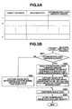
- the appropriate ISO sensitivity is decided as mentioned above and the object distance is known. Accordingly, it is also possible to store in the MROM 17 the correspondence table of the ISO sensitivity, the object distance or the like and an amount of stroboscope emission light as shown in FIG. 5A, and read out an amount of stroboscope emission light corresponding to the ISO sensitivity and the object distance from the correspondence table so as to control an amount of light emitted from the stroboscope 15 at the time of image capturing without executing the pre-emission of light (see the flow chart of FIG. 5B).
- step SB1 it is determined whether or not the image capturing condition includes the stroboscope light emission. If the image capturing condition does not include the stroboscope light emission, an image is captured without stroboscope light emission and with the above shutter speed, diaphragm value, and ISO sensitivity set during the shutter key half pressing operation (step SB6).
- the image capturing condition includes the stroboscope light emission
- an amount of stroboscope emission light corresponding to ISO-capt and the object distance D-af are read from the correspondence table (step SB2).
- An image is captured with stroboscope light emission of which amount is read at step SB2 and with the above shutter speed and diaphragm value set during the shutter key half pressing operation and ISO-capt (step SB3).
- the captured image data is compressed (step SB4), and the compressed image data is recorded in the flash memory 18 (step SB5).
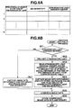
- the ISO sensitivity is decided by the comparison of the stroboscope maximum reaching distance and the object distance in this embodiment, it is also possible to decide an amount of stroboscope emission light and the ISO sensitivity based on the brightness (an amount of light) of the object obtained by executing the pre-emission of light.
- the MROM 17 the correspondence table of the object brightness (luminance value of the image signal) at the time of the pre-emission of light, the ISO sensitivity, and an amount of stroboscope emission light as shown in FIG.
- step SC1 it is determined whether or not the image capturing condition includes the stroboscope light emission. If the image capturing condition does not include the stroboscope light emission, an image is captured without stroboscope light emission and with the above shutter speed, diaphragm value, and ISO sensitivity set during the shutter key half pressing operation (step SC7).
- the stroboscope 15 pre-emits light at step SC2.
- An amount of light emission of the stroboscope 15 and ISO sensitivity corresponding to the brightness of the image signal obtained at the time of pre-emission of light are read out from the correspondence table (step SC3).
- An image is captured with stroboscope light emission of which amount is read at step SC3 and with the above shutter speed and diaphragm value set during the shutter key half pressing operation and ISO-capt (step SC4).
- the captured image data is compressed (step SC5), and the compressed image data is recorded in the flash memory 18 (step SC6).
- the MROM 17 stores in the MROM 17 the ISO sensitivity, on or off of the stroboscope light emission, and an amount of stroboscope emission light (only in the case of the stroboscope light emission is on) corresponding to the object brightness (luminance value of the image signal), and read out the ISO sensitivity value, on or off of the stroboscope light emission, and an amount of stroboscope emission light corresponding to the measured object brightness so as to execute the image capturing process based on the readout information.
- the object brightness is calculated based on the through image in step S1 of FIG. 3, it is also possible to provide an optical sensor and obtain the object brightness by correcting as needed the brightness detected by the optical sensor.
- the object distance D-af is calculated by using the focus setting table by the contrast AF method in step S2 of FIG. 3, it is also possible to provide a distance measuring sensor such as an external phase difference sensor and obtain the object distance D-af by the detection value of the distance measuring sensor.
- the present invention can be practiced as a computer readable recording medium in which a program for allowing the computer to function as predetermined means, allowing the computer to realize a predetermined function, or allowing the computer to conduct predetermined means.
- a program for allowing the computer to function as predetermined means allowing the computer to realize a predetermined function, or allowing the computer to conduct predetermined means.
- the present invention can also be applied in a camera stored in a portable information terminal such as a portable phone.
Landscapes
- Engineering & Computer Science (AREA)
- Multimedia (AREA)
- Signal Processing (AREA)
- Studio Devices (AREA)
- Stroboscope Apparatuses (AREA)
- Exposure Control For Cameras (AREA)
- Indication In Cameras, And Counting Of Exposures (AREA)
Abstract
Description
Claims (21)
- An image capture device comprising
means (15) for emitting light;
image capture means (2) for outputting an image signal;
means (3) for detecting a brightness of an object, characterized by further comprising:first control means (3) for disabling the light emitting means (15) and setting a sensitivity which is in accordance with the brightness of the object detected by the detecting means (3) and which is lower than a predetermined sensitivity;second control means (3) for enabling the light emitting means (15) and setting a sensitivity which is lower than the predetermined sensitivity; andmeans (12) for amplifying the image signal output form the image capture means (2) by an amplifying factor according to the sensitivity set by one of the first and second control means (3). - The image capture device according to claim 1, characterized by further comprising:means (3) for selecting one of the first and second control means (3) based on the brightness of the object detected by the detecting means (3).
- The image capture device according to claim 1, characterized by further comprising:means (3) for determining whether or not an image signal having an appropriate brightness is obtained by the first control means (3); andmeans (3) for selecting one of the first and second control means (3) based on a result of determination by the determining means (3).
- The image capture device according to claim 1, characterized by further comprising:means (3) for obtaining an object distance to the object, and characterized in thatthe second control means (3) comprises means for obtaining a sensitivity according to the object distance and a maximum amount of light emitted from the light emitting means (15) and means for setting the obtained sensitivity.
- The image capture device according to claim 4, characterized by further comprising:a shutter key (13) for instructing an image capture upon a full pressing, and characterized in thatthe object distance obtaining means (3) obtains the object distance upon a half pressing of the shutter key (13); andthe sensitivity obtaining means (3) obtains the sensitivity upon the half pressing of the shutter key (13).
- The image capture device according to claim 4, characterized by further comprising:auto-focus means (3) for searching a focusing position by moving a focus lens (5) in an optical axis direction, and characterized in thatthe object distance obtaining means (3) obtains the object distance based on the focusing position searched by the auto-focus means (3).
- The image capture device according to claim 4, characterized in that said sensitivity obtaining means obtains the sensitivity based on the object distance using a relation among light reachable distances of the light emitting means (15), the maximum amount of light emitted from the light emitting means (15), and the sensitivity so that the object distance approximates the light reachable distance.
- The image capture device according to claim 7, characterized in that
the light reachable distance based on the maximum amount of light emitted from the light emitting means (15) and the predetermined sensitivity, and further comprising:means (14) for alarming that a light cannot reach the object when the object distance is longer that the light reachable distance. - The image capture device according to claim 1, characterized in that the detecting means (3) detects the brightness of the object based on a brightness of the image signal output from the image capture means (2).
- The image capture device according to claim 1, characterized in that the second control means (3) further comprises means for setting the predetermined sensitivity.
- The image capture device according to claim 1, characterized in that the second control means (3) comprises:pre-emission means (3) for causing the light emitting means (15) to pre-emit light; andlight emission amount determining means for determining a light emission amount of the light emitting means (15) based on a brightness of an image signal which is output from the image capture means (2) at the time of pre-emission of light by the pre-emission means (3) and which is amplified by the amplifying means (12) by the amplifying factor according to a sensitivity lower than the predetermined sensitivity, andthe second control means (3) causes the light emitting means (15) to emit a light by an amount of light determined by the light emission amount determining means.
- The image capture device according to claim 11, characterized by further comprising:a shutter key (13), and characterized in thatthe pre-emission means causes the light emitting means (15) to pre-emit light upon a pressing of the shutter key (13); andthe light emission amount determining means determines a light emission amount of the light emitting means (15) upon the pressing of the shutter key (13).
- The image capture device according to claim 1, characterized by further comprising:means (3) for obtaining an object distance to the object, and characterized in thatthe second control means (3) comprises means for determining a light emission amount of the light emitting means (15) based on the object distance and a sensitivity lower than the predetermined sensitivity, andthe second control means (3) causes the light emitting means (15) to emit a light by an amount of light determined by the light emission amount determining means.
- The image capture device according to claim 1, characterized in that the second control means (3) comprises:pre-emission means (3) for causing the light emitting means (15) to pre-emit light; andmeans for determining a light emission amount of the light emitting means (15) and a sensitivity based on a brightness of an image signal which is output from the image capture means (2) at the time of pre-emission of light by the pre-emission means (3), andthe second control means (3) causes the light emitting means (15) to emit a light by an amount of light determined by the light emission amount determining means and sets the sensitivity which is determined by the sensitivity determining means.
- The image capture device according to claim 1, characterized by further comprising:shutter speed control means (3) for setting a shutter speed which is in accordance with the brightness of the object detected by the detecting means (3) and which is slower than a predetermined shutter speed.
- The image capture device according to claim 15, characterized by further comprising:means (3) for determining whether or not an image signal having an appropriate brightness is obtained by the shutter speed control means (3), and characterized in that, when the determining means (3) determines that the image signal having an appropriate brightness is not obtained by a control of the shutter speed control means (3), the first control means (3) sets a sensitivity which is in accordance with the brightness of the object detected by the detecting means (3) and which is lower than the predetermined sensitivity.
- The image capture device according to claim 1, characterized by further comprising diaphragm control means (3) for controlling a diaphragm device (6) based on the brightness of the object detected by the detecting means (3).
- The image capture device according to claim 1, characterized by further comprising means (3) for compressing the image signal amplified by the amplifying means (12).
- The image capture device according to claim 1, characterized by further comprising means (3) for recording the image signal amplified by the amplifying means (12) in a memory (18).
- The image capture device according to claim 19, characterized by further comprising means (14) for displaying the image signal recorded in the memory (18) by the recording means (3).
- A sensitivity setting method for an image capture device (1) which causes light emitting means to operate according to a brightness of an object and amplifies an image signal by an amplifying factor according to the set sensitivity, the method characterized by comprising:a step for disabling the light emitting means (15), setting a sensitivity which is in accordance with the brightness of the object detected by the detecting means (3) and which is lower than a predetermined sensitivity; anda step for enabling the light emitting means (15) and setting a sensitivity which is lower than the predetermined sensitivity.
Applications Claiming Priority (2)
| Application Number | Priority Date | Filing Date | Title |
|---|---|---|---|
| JP2004008905A JP4222213B2 (en) | 2004-01-16 | 2004-01-16 | Camera device, photographing sensitivity setting program, and photographing sensitivity setting method |
| JP2004008905 | 2004-01-16 |
Publications (2)
| Publication Number | Publication Date |
|---|---|
| EP1578117A2 true EP1578117A2 (en) | 2005-09-21 |
| EP1578117A3 EP1578117A3 (en) | 2006-07-12 |
Family
ID=34747198
Family Applications (1)
| Application Number | Title | Priority Date | Filing Date |
|---|---|---|---|
| EP05000746A Ceased EP1578117A3 (en) | 2004-01-16 | 2005-01-14 | Image capture device and sensitivity setting method therefor |
Country Status (3)
| Country | Link |
|---|---|
| US (1) | US7525592B2 (en) |
| EP (1) | EP1578117A3 (en) |
| JP (1) | JP4222213B2 (en) |
Cited By (1)
| Publication number | Priority date | Publication date | Assignee | Title |
|---|---|---|---|---|
| CN103248823A (en) * | 2013-04-12 | 2013-08-14 | 广东欧珀移动通信有限公司 | Photographing method, device and system |
Families Citing this family (24)
| Publication number | Priority date | Publication date | Assignee | Title |
|---|---|---|---|---|
| JP4999306B2 (en) * | 2005-09-30 | 2012-08-15 | カシオ計算機株式会社 | Imaging apparatus, imaging method, and program |
| JP4615458B2 (en) * | 2006-03-08 | 2011-01-19 | 富士フイルム株式会社 | Exposure control method and imaging apparatus |
| JP4533860B2 (en) | 2006-03-09 | 2010-09-01 | 富士フイルム株式会社 | Imaging apparatus and exposure control method |
| US7822328B2 (en) * | 2006-07-03 | 2010-10-26 | Samsung Electronics Co., Ltd. | Method for controlling digital photographing apparatus and digital photographing apparatus adopting the method |
| JP5004544B2 (en) * | 2006-09-29 | 2012-08-22 | 富士フイルム株式会社 | Imaging apparatus and exposure control method |
| JP4750063B2 (en) * | 2007-03-28 | 2011-08-17 | 富士フイルム株式会社 | Imaging apparatus and imaging method |
| TW200930066A (en) * | 2007-12-21 | 2009-07-01 | Altek Corp | Digital photogrphic camera with brightness compensation and compensation method thereof |
| KR100945440B1 (en) * | 2008-07-22 | 2010-03-05 | 삼성전기주식회사 | How to control the flash firing of your mobile camera |
| JP4812846B2 (en) * | 2009-02-19 | 2011-11-09 | アキュートロジック株式会社 | Imaging apparatus and imaging method |
| JP2010211773A (en) | 2009-03-12 | 2010-09-24 | Sony Corp | Image process apparatus, image process method and computer program |
| JP5451316B2 (en) | 2009-10-28 | 2014-03-26 | キヤノン株式会社 | Imaging apparatus and light emission control method |
| JP4547465B2 (en) * | 2010-04-08 | 2010-09-22 | 富士フイルム株式会社 | Imaging apparatus and exposure control method |
| TWI389560B (en) * | 2010-05-14 | 2013-03-11 | Ability Entpr Co Ltd | Flashing control method for a digital camera |
| TWI405458B (en) * | 2010-07-02 | 2013-08-11 | Altek Corp | Digital camera sensitivity adjustment method |
| US8294785B2 (en) * | 2010-07-02 | 2012-10-23 | Altek Corporation | Method for adjusting photosensitiveness of digital camera |
| JP5597078B2 (en) | 2010-09-17 | 2014-10-01 | キヤノン株式会社 | Imaging apparatus and control method thereof |
| JP5657362B2 (en) * | 2010-12-06 | 2015-01-21 | オリンパスイメージング株式会社 | Image capturing apparatus and method for controlling image capturing apparatus |
| WO2014135739A1 (en) * | 2013-03-06 | 2014-09-12 | Nokia Corporation | Sliding accessory lens mount with automatic mode adjustment |
| JP2014235410A (en) * | 2013-06-05 | 2014-12-15 | 株式会社デンソー | Image capture controller |
| CN104349072A (en) * | 2013-08-09 | 2015-02-11 | 联想(北京)有限公司 | Control method, device and electronic equipment |
| JP5704476B1 (en) * | 2014-06-24 | 2015-04-22 | 株式会社ビジョナリスト | Digital photo analysis apparatus and digital photo analysis program |
| US10409141B2 (en) * | 2017-09-20 | 2019-09-10 | Qualcomm Incorporated | System and method for improved camera flash |
| US11039066B2 (en) * | 2018-06-28 | 2021-06-15 | Canon Kabushiki Kaisha | Image pickup apparatus having a plurality of settable image capturing modes, method for controlling the same, and non-transitory computer-readable storage medium |
| JP2024131362A (en) * | 2023-03-16 | 2024-09-30 | トヨタ自動車株式会社 | Infrared light projection control device, infrared light projection control method, and infrared light projection control program |
Family Cites Families (23)
| Publication number | Priority date | Publication date | Assignee | Title |
|---|---|---|---|---|
| US4549801A (en) * | 1983-03-21 | 1985-10-29 | W. Haking Enterprises Limited | Automatic focussing camera with automatic aperture setting |
| EP0320828B1 (en) * | 1987-12-17 | 1995-05-03 | Mitsubishi Denki Kabushiki Kaisha | Methods for transmitting and displaying a still picture image in a still picture video telephone apparatus |
| US5400113A (en) * | 1988-03-16 | 1995-03-21 | Nikon Corporation | Control device for preventing red-eye effect on camera |
| JPH0457041A (en) * | 1990-06-27 | 1992-02-24 | Minolta Camera Co Ltd | Camera for storing fault information |
| DE69128591T2 (en) * | 1990-10-04 | 1998-05-20 | Canon Kk | Image scanner |
| JP2913490B2 (en) * | 1990-10-16 | 1999-06-28 | 株式会社ニコン | Camera automatic light control device |
| JP3009561B2 (en) * | 1993-04-26 | 2000-02-14 | 富士写真フイルム株式会社 | Still video camera and strobe light emission control data adjusting device |
| US6583811B2 (en) * | 1996-10-25 | 2003-06-24 | Fuji Photo Film Co., Ltd. | Photographic system for recording data and reproducing images using correlation data between frames |
| JPH10322580A (en) * | 1997-05-20 | 1998-12-04 | Minolta Co Ltd | Electronic still camera |
| JP3873157B2 (en) * | 1997-11-13 | 2007-01-24 | カシオ計算機株式会社 | Electronic camera device and imaging method |
| US6744471B1 (en) * | 1997-12-05 | 2004-06-01 | Olympus Optical Co., Ltd | Electronic camera that synthesizes two images taken under different exposures |
| JP4024402B2 (en) | 1998-10-22 | 2007-12-19 | 株式会社リコー | camera |
| JP2001177763A (en) | 1999-12-15 | 2001-06-29 | Fuji Photo Film Co Ltd | Digital camera and control method thereof |
| JP2001230970A (en) | 2000-02-16 | 2001-08-24 | Fuji Photo Film Co Ltd | Imaging device |
| JP2001285707A (en) | 2000-03-29 | 2001-10-12 | Canon Inc | Imaging device, control method thereof, and memory medium |
| JP3473552B2 (en) | 2000-06-15 | 2003-12-08 | ミノルタ株式会社 | Digital still camera |
| JP3744388B2 (en) | 2001-06-26 | 2006-02-08 | ソニー株式会社 | Imaging apparatus and imaging method |
| JP2004104765A (en) * | 2002-07-17 | 2004-04-02 | Canon Inc | Imaging device and lighting device |
| US7218353B2 (en) * | 2001-12-26 | 2007-05-15 | Nikon Corporation | Electronic camera that selectively performs different exposure calculation routines |
| JP2003319255A (en) * | 2002-02-20 | 2003-11-07 | Casio Comput Co Ltd | Flash device-equipped imaging device, flash device control method and imaging method, and imaging device control program |
| JP3967165B2 (en) * | 2002-03-27 | 2007-08-29 | 富士フイルム株式会社 | Digital still camera |
| JP2004088243A (en) * | 2002-08-23 | 2004-03-18 | Canon Inc | Imaging apparatus and method and apparatus for controlling imaging apparatus |
| JP4151387B2 (en) * | 2002-11-15 | 2008-09-17 | セイコーエプソン株式会社 | Automatic image quality adjustment according to subject brightness |
-
2004
- 2004-01-16 JP JP2004008905A patent/JP4222213B2/en not_active Expired - Fee Related
-
2005
- 2005-01-12 US US11/035,268 patent/US7525592B2/en active Active
- 2005-01-14 EP EP05000746A patent/EP1578117A3/en not_active Ceased
Cited By (1)
| Publication number | Priority date | Publication date | Assignee | Title |
|---|---|---|---|---|
| CN103248823A (en) * | 2013-04-12 | 2013-08-14 | 广东欧珀移动通信有限公司 | Photographing method, device and system |
Also Published As
| Publication number | Publication date |
|---|---|
| US20050157206A1 (en) | 2005-07-21 |
| US7525592B2 (en) | 2009-04-28 |
| EP1578117A3 (en) | 2006-07-12 |
| JP2005204120A (en) | 2005-07-28 |
| JP4222213B2 (en) | 2009-02-12 |
Similar Documents
| Publication | Publication Date | Title |
|---|---|---|
| US7525592B2 (en) | Image capture device with automatic adjusting function for sensitivity | |
| KR100868595B1 (en) | Image pickup apparatus, exposure control method, and computer readable medium installed in the image pickup apparatus | |
| US8098287B2 (en) | Digital camera with a number of photographing systems | |
| US7164446B2 (en) | Digital camera and method of controlling the same | |
| CN101843094B (en) | Camera device and control method thereof | |
| US8891952B2 (en) | Image sensing apparatus, control method, and user interface display apparatus | |
| US20070019937A1 (en) | Image-taking apparatus | |
| US7667175B2 (en) | Imaging device driver and auto focus unit | |
| US7250974B2 (en) | Image pickup apparatus with improved auto focusing and method of autofocusing | |
| JP5869808B2 (en) | Imaging apparatus and control method thereof | |
| JP2003319255A (en) | Flash device-equipped imaging device, flash device control method and imaging method, and imaging device control program | |
| EP1860871A1 (en) | Image pickup apparatus and image pickup control method | |
| US8154621B2 (en) | Photographing apparatus and photographing method | |
| JP2008070611A (en) | Imaging apparatus, exposure condition adjusting method and program | |
| US7801429B2 (en) | Image taking apparatus | |
| US7697835B2 (en) | Imaging apparatus | |
| CN100447656C (en) | Camera device and camera method | |
| JP4855155B2 (en) | Imaging apparatus and imaging method using the same | |
| JP4688485B2 (en) | Imaging device with auxiliary light function | |
| KR100965322B1 (en) | Exposure Control Device and Method of Digital Camera | |
| JP2009290510A (en) | Image pickup apparatus | |
| JP2008219334A (en) | Electronic camera | |
| JP4888068B2 (en) | Electronic camera | |
| JP2010147554A (en) | Electronic camera | |
| JP2006349908A (en) | Imaging apparatus and imaging method |
Legal Events
| Date | Code | Title | Description |
|---|---|---|---|
| PUAI | Public reference made under article 153(3) epc to a published international application that has entered the european phase |
Free format text: ORIGINAL CODE: 0009012 |
|
| 17P | Request for examination filed |
Effective date: 20050114 |
|
| AK | Designated contracting states |
Kind code of ref document: A2 Designated state(s): AT BE BG CH CY CZ DE DK EE ES FI FR GB GR HU IE IS IT LI LT LU MC NL PL PT RO SE SI SK TR |
|
| AX | Request for extension of the european patent |
Extension state: AL BA HR LV MK YU |
|
| PUAL | Search report despatched |
Free format text: ORIGINAL CODE: 0009013 |
|
| AK | Designated contracting states |
Kind code of ref document: A3 Designated state(s): AT BE BG CH CY CZ DE DK EE ES FI FR GB GR HU IE IS IT LI LT LU MC NL PL PT RO SE SI SK TR |
|
| AX | Request for extension of the european patent |
Extension state: AL BA HR LV MK YU |
|
| 17Q | First examination report despatched |
Effective date: 20061004 |
|
| AKX | Designation fees paid |
Designated state(s): DE FR GB |
|
| 17Q | First examination report despatched |
Effective date: 20061004 |
|
| STAA | Information on the status of an ep patent application or granted ep patent |
Free format text: STATUS: THE APPLICATION HAS BEEN REFUSED |
|
| 18R | Application refused |
Effective date: 20080626 |