JP4812846B2 - Imaging apparatus and imaging method - Google Patents
Imaging apparatus and imaging method Download PDFInfo
- Publication number
- JP4812846B2 JP4812846B2 JP2009036478A JP2009036478A JP4812846B2 JP 4812846 B2 JP4812846 B2 JP 4812846B2 JP 2009036478 A JP2009036478 A JP 2009036478A JP 2009036478 A JP2009036478 A JP 2009036478A JP 4812846 B2 JP4812846 B2 JP 4812846B2
- Authority
- JP
- Japan
- Prior art keywords
- value
- distance
- luminance
- subject
- light emission
- Prior art date
- Legal status (The legal status is an assumption and is not a legal conclusion. Google has not performed a legal analysis and makes no representation as to the accuracy of the status listed.)
- Active
Links
Images


Landscapes
- Stroboscope Apparatuses (AREA)
- Studio Devices (AREA)
- Exposure Control For Cameras (AREA)
Description
本発明は、撮像装置及び撮像方法に関し、特には、閃光撮影の際に撮影条件に応じて適切な画像が得られるように、露出プログラムに基づいて撮影を行う撮像装置及び撮像方法に関する。 The present invention relates to an imaging apparatus and an imaging method, and more particularly, to an imaging apparatus and an imaging method that perform imaging based on an exposure program so that an appropriate image can be obtained according to imaging conditions during flash imaging.
従来、デジタルカメラ等の撮像装置において、被写体の明るさに応じた適切な露出値(EV値)を決定し、その露出値を得るために、シャッター速度(TV値)、絞り値(AV値)、ISO感度(SV値)、等を自動的に制御する自動露出(AE)機能を備えたものが知られている。 2. Description of the Related Art Conventionally, in an imaging apparatus such as a digital camera, an appropriate exposure value (EV value) corresponding to the brightness of a subject is determined, and in order to obtain the exposure value, a shutter speed (TV value), an aperture value (AV value) A device having an automatic exposure (AE) function for automatically controlling ISO sensitivity (SV value) and the like is known.
この際、同一のEV値に対して、TV値とAV値との組み合わせが複数存在し、更には、これらとISO感度との組み合わせが複数存在する。そして、デジタルカメラ等の撮像装置では、これらの組み合わせを示すプログラム線図(露出線図)が撮影モードに対応付けて予め備えられ、このプログラム線図に基づいて、露出制御を行う技術が知られている。 At this time, there are a plurality of combinations of TV values and AV values for the same EV value, and there are a plurality of combinations of these and ISO sensitivities. In an imaging apparatus such as a digital camera, a program diagram (exposure diagram) indicating these combinations is provided in advance in association with a shooting mode, and a technique for performing exposure control based on this program diagram is known. ing.
また、近年のデジタルカメラでは、ストロボ(ストロボはストロボリサーチ社の商標である)などの閃光装置を備えたものが一般的であって、シャッター速度と絞り値との組み合わせのみで所望の露出が得られない低照度の際には、ストロボ光を発光させて露出を制御する技術も知られている(例えば、特許文献1、2参照)。
In addition, recent digital cameras generally have a flash device such as a strobe (a strobe is a trademark of Strobe Research), and a desired exposure can be obtained only by a combination of a shutter speed and an aperture value. There is also known a technique of controlling exposure by emitting strobe light when the illumination is low, for example (see
この際、デジタルカメラでは、プレビュー画像から得られる輝度情報を参照して露出調整が行われる。また、本撮影の際にストロボ光が必要な低照度時には、プレビュー用の画像情報を得ることが困難になるため、デジタルカメラに備えられた予備発光装置を用いて、本撮影前に予備発光させてプレビュー画像を取得し、本撮影時の露出を制御する。 At this time, in the digital camera, exposure adjustment is performed with reference to luminance information obtained from the preview image. In addition, it is difficult to obtain image information for preview at low illuminance, which requires strobe light during actual shooting. Therefore, the preliminary light emission device provided in the digital camera can be used for preliminary light emission before the actual shooting. To obtain a preview image and control the exposure during actual shooting.
つまり、撮影の際に、露光のための閃光装置の発光に先立って予備発光を行い、この予備発光による被写体からの反射光を受光して、その受光量に応じてストロボ発光の有無を選択したり露出量を調光したりする技術(所謂、TTL方式の露光制御である)が用いられている(例えば、特許文献3、4参照)。
In other words, at the time of shooting, preliminary light emission is performed prior to the light emission of the flash device for exposure, the reflected light from the subject due to this preliminary light emission is received, and the presence or absence of strobe light emission is selected according to the amount of light received. In other words, a technique for adjusting the exposure amount (so-called TTL exposure control) is used (see, for example,
ところで、調光の際に、予備発光で得られた画面全体の受光量を単一的に用い、この受光量に応じて調光すれば、撮像シーンに主たる被写体(以下、主被写体ともいう)の他に背景などの従属的な種々の被写体が含まれるときには、一般的に、調光量が撮影シーンにおける全ての被写体全体の撮影距離と反射率に関連付けられて得られるため、主被写体に対して露出オーバー(露出過大)や露出アンダー(露出過小)になる虞がある。 By the way, when the light control is performed, the received light amount of the entire screen obtained by the preliminary light emission is used singly, and the light is adjusted according to the received light amount, the main subject in the imaging scene (hereinafter also referred to as the main subject). In addition to various subordinate subjects such as the background, in general, the light control amount is obtained in association with the shooting distance and reflectance of all the subjects in the shooting scene. May be overexposed (overexposed) or underexposed (underexposed).
例えば、調光の際に、主被写体と背景との間に距離差がある場合、距離が遠いほどストロボ光が拡散して減衰するので、背景のストロボ反射光が小さく(暗く)、背景に較べて被写体のストロボ反射光が大きく(明るく)なり、撮影の際に、撮像画面全体において主被写体が露出オーバーになる現象が発生する。 For example, when dimming, if there is a distance difference between the main subject and the background, the strobe light diffuses and attenuates as the distance increases, so the strobe reflected light from the background is smaller (darker) and compared to the background. As a result, the stroboscopic reflected light of the subject becomes large (brighter), and a phenomenon occurs in which the main subject is overexposed on the entire imaging screen during shooting.
また、調光の際に、被写体自体の反射率に起因して、適正な発光量に対しての調光誤差が生じる虞がある。例えば、主被写体の背景に白壁や光沢面を有する反射率の高い物体などが存在しているときに、背景からの反射光量を抑制するように調光すると、撮影の主体となる主被主体に対して露出不足になってしまう虞がある。 Further, during dimming, there is a possibility that a dimming error with respect to an appropriate light emission amount may occur due to the reflectance of the subject itself. For example, if there is a highly reflective object with a white wall or glossy surface in the background of the main subject, dimming to reduce the amount of reflected light from the background, the main subject that is the subject of the shooting On the other hand, there is a risk of underexposure.
しかしながら、従来の露出プログラム線図によれば、プレビュー画像で取得した輝度情報に基づいてAV、TV、SV等の設定座標を備えているが、撮影シーンに応じてストロボの発光量を任意に設定できるようなストロボ座標のプログラム線図を備えていないので、さらに改善の余地があった。また、主被写体と背景との距離差に応じたストロボ制御のプログラム線図を備えていないので、改善の余地があった。 However, according to the conventional exposure program diagram, the setting coordinates of AV, TV, SV, etc. are provided based on the luminance information acquired in the preview image, but the flash emission amount is arbitrarily set according to the shooting scene. There is room for further improvement because it does not have a strobe coordinate program diagram that can be used. Also, since there is no program chart for strobe control corresponding to the distance difference between the main subject and the background, there is room for improvement.
例えば、ISO感度を下げてストロボ光を増加すると、主被写体とその背景に距離差が大きい際に、背景に照射されるストロボ光量が激減して背景が極度の暗く写ってしまう虞がある。一方、この現象を回避するために、ストロボ光を抑えてISO感度を上げると、S/N比が悪化するという問題が生じる。 For example, when the ISO sensitivity is lowered and the strobe light is increased, when the distance between the main subject and the background is large, the amount of strobe light applied to the background may be drastically reduced and the background may appear extremely dark. On the other hand, if the ISO sensitivity is increased by suppressing the strobe light in order to avoid this phenomenon, there arises a problem that the S / N ratio deteriorates.
そこで、本発明は、主被写体と背景との距離差に応じたストロボ制御のプログラム線図を備え、適切にストロボ光量及び露出条件を設定できると共に、利便性が優れた撮像方法を提供することを目的とする。
Therefore, the present invention provides a program diagram for strobe control corresponding to the difference in distance between the main subject and the background, and can provide an imaging method that can set the strobe light amount and exposure conditions appropriately and is excellent in convenience. Objective.
かかる目的を達成するためになされた請求項1に記載の発明は、複数の光電変換素子がマトリクス状に配置され、入射光量に応じて撮影された被写体の画像データを出力する撮像素子と、撮影の際に、前記被写体に所定の光量の補助光を発光する閃光装置と、撮影画面の明るさに応じて前記閃光装置の発光量及び前記撮像素子のISO感度を設定する閃光プログラム線図を用いる閃光プログラムと、前記閃光プログラムを用いて前記被写体を撮影する際の入射光量を調節する露出制御部と、を備えた撮像装置の撮像方法において、前記光電変換素子の夫々から出力された画像信号を画素信号とした際に、撮影画面において、所定の画素信号の数を一単位とする複数の輝度をマトリクス状に生成し、前記一単位毎に、当該撮像装置から前記被写体までの距離を検出する距離情報検出手順と、前記一単位毎の距離の平均値を求めて、前記一単位毎に前記平均値と前記被写体までの距離との差分値の絶対値を求め、次いで、該差分値の絶対値の合計を前記一単位の数で除算して正規化係数を算出し、該算出された正規化係数に基づいて、前記正規化係数が大きくなるに従って前記閃光装置の発光量を減少させて前記撮像素子のISO感度を上げるように、前記閃光プログラム線図における前記閃光装置の発光量と前記撮像素子のISO感度との割合を補正する露出生成手順と、を用いることを特徴とする。
The invention according to
請求項1に記載の撮像方法によれば、撮影画面において、所定の画素信号の数を一単位とする複数の輝度をマトリクス状に生成し、一単位毎に、撮像装置から被写体までの距離を検出する距離情報検出手順と、一単位毎の距離の平均値を求めて、一単位毎に平均値と被写体までの距離との差分値の絶対値を求め、次いで、差分値の絶対値の合計を一単位の数で除算して正規化係数を算出し、算出された正規化係数に基づいて、正規化係数が大きくなるに従って閃光装置の発光量を減少させて撮像素子のISO感度を上げるように、閃光プログラム線図における閃光装置の発光量と撮像素子のISO感度との割合を補正する露出生成手順を用いているので、被写体と背景との距離差に応じて、適切に発光量及び露出条件を設定できて利便性を向上できる。
According to the imaging method of
次に、請求項2に記載の発明は、請求項1に記載の撮像方法において、当該撮像装置にシャッター及び絞りを備え、前記閃光プログラム線図として、前記撮影画面の明るさを表す輝度情報に対応付けて、前記発光量及び前記ISO感度のパラメータと前記露出制御部の露出値とを設定する第1プログラム線図と、前記露出値に対応付けて、シャッター速度と絞り値とを設定する第2プログラム線図と、前記発光量及び前記ISO感度のパラメータに対応付けて、前記撮像素子のISO感度と前記閃光装置の発光量とを設定する第3プログラム線図と、を用いることを特徴とする。
Next, the invention described in
請求項2に記載の撮像方法によれば、閃光プログラム線図として、画面の明るさを表す輝度情報に対応付けて、閃光装置の発光量及びISO感度のパラメータと露出制御部の露出値とを設定する第1プログラム線図と、露出値に対応付けて、シャッター速度と絞り値とを設定する第2プログラム線図と、発光量及びISO感度のパラメータに対応付けて、撮像素子のISO感度と閃光装置の発光量とを設定する第3プログラム線図と、を用いているので、撮影画面に応じて、シャッター速度、絞り値、ISO感度、閃光装置の発光量等を設定できて高品位な画像を得ることができて利便性を向上できる。
According to the imaging method of the second aspect, as the flash program diagram, the light emission amount and ISO sensitivity parameters of the flash device and the exposure value of the exposure control unit are associated with the luminance information indicating the brightness of the screen. The first program diagram to be set, the second program diagram to set the shutter speed and the aperture value in association with the exposure value, the ISO sensitivity of the image sensor in association with the light emission amount and ISO sensitivity parameters a third program diagram for setting the light emission amount of the flash device, than are used, depending on the shooting screen, shutter speed, aperture value, ISO sensitivity, high quality and can set the light emission amount of the flash device A convenient image can be obtained.
次に、請求項3に記載の発明は、請求項1又は請求項2に記載の撮像方法において、本撮影前に予備発光する予備発光手順を備え、前記距離情報検出手順が、前記撮影画面の特定領域に対応する当該撮像装置から前記被写体までの距離の基準値を取得する基準距離取得手順と、前記予備発光無しに撮影して得られた前記被写体の画像データに基づいて、所定の画素信号の数を一単位とする複数の第1輝度を、所定の画像領域にわたってマトリクス状に生成する第1輝度生成手順と、前記予備発光して撮影して得られた前記被写体の画像データに基づいて、前記第1輝度と対になるように、前記所定の画素信号の数を一単位とする複数の第2輝度を生成する第2輝度生成手順と、前記一単位毎に、前記第2輝度から前記第1輝度を減算して、前記予備発光の輝度成分を算出する輝度差算出手順と、前記一単位毎に、前記第1輝度と、前記輝度差算出手順で算出された予備発光の輝度成分とを、夫々、所定の目標輝度と比較して該目標輝度との比を求め、この比を用いて、当該撮像装置から前記被写体までの第1の被写体距離を求める際の第1及び第2のパラメータを生成するパラメータ生成手順と、前記第1及び第2のパラメータと、前記第2輝度生成手順における前記予備発光の際の露出値とに基づいて、前記一単位毎に、前記第1の被写体距離を生成する第1距離情報生成手順と、前記特定領域に位置する前記第1の被写体距離と前記被写体距離の基準値との差分を算出してこの差分を補正値とする補正値算出手順と、前記一単位毎に、前記補正値算出手順で生成された補正値を用いて、前記第1の被写体距離を補正し、第2の被写体距離を生成する第2距離情報生成手順と、を用い、前記パラメータ生成手順が、前記第1のパラメータをMVa、前記第2のパラメータをMVb、前記目標輝度をYt、前記第1輝度をYa、前記予備発光の輝度成分をYbと表した際に、前記第1のパラメータをMVa=LOG2(Ya/Yt)、前記第2のパラメータをMVb=LOG2(Yb/Yt)、の演算式で算出し、前記第1距離情報生成手順が、前記第1の被写体距離のアペックス値をDX、前記第1輝度生成手順及び第2輝度生成手順における撮影の際のシャッタースピードのアペックス値をTV、前記閃光装置の予備発光のガイドナンバーのアペックス値をGVと表した際に、前記第1の被写体距離のアペックス値をDX=(MVa−MVb)/2−(5−TV−GV)/2、の演算式で算出し、前記補正値算出手順が、前記補正値をOFFSET、前記特定領域における第1の被写体距離のアペックス値をDX(base)、前記特定領域における被写体距離の基準値のアペックス値をDV(base)と表した際に、前記補正値をOFFSET=DX(base)−DV(base)、の演算式で算出し、前記第2距離情報生成手順が、前記第2の被写体距離のアペックス値をDV、前記第1の被写体距離のアペックス値をDX、前記補正値をOFFSETと表した際に、前記第2の被写体距離のアペックス値をDV=DX−OFFSET、の演算式で算出することにより、前記一単位毎に前記第2の被写体距離を推定演算し、前記一単位毎に、前記第2の被写体距離を、前記撮像装置から前記被写体までの距離として検出する、ことを特徴とする。
Next, the invention according to
請求項3に記載の撮像方法によれば、撮影画面全体にマトリクス状に複数生成された第1、第2輝度に対応付けて、夫々、被写体距離(第2の被被写体距離である)を測定できる。
By the imaging method according to
本発明の撮像方法は、撮影画面において、所定の画素信号の数を一単位とする複数の輝度をマトリクス状に生成し、一単位毎に、撮像装置から被写体までの距離を検出し、次いで、一単位毎の距離の平均値を求めて、一単位毎に平均値と被写体までの距離との差分値の絶対値を求め、次いで、差分値の絶対値の合計を一単位の数で除算して正規化係数を算出し、算出された正規化係数に基づいて、正規化係数が大きくなるに従って閃光装置の発光量を減少させて前記撮像素子のISO感度を上げるように、閃光プログラム線図における閃光装置の発光量と撮像素子のISO感度との補正することにより、被写体と背景との距離差に応じて、適切にストロボ光量及び露出条件を設定できて利便性を向上できる。
The imaging method of the present invention generates a plurality of luminances in a matrix form with a predetermined number of pixel signals as one unit on a shooting screen, detects the distance from the imaging device to the subject for each unit, and then Find the average distance for each unit, find the absolute value of the difference between the average value and the distance to the subject for each unit, and then divide the sum of the absolute values of the difference values by the number of units. In the flash program diagram so as to increase the ISO sensitivity of the imaging device by decreasing the light emission amount of the flash device as the normalization coefficient increases, based on the calculated normalization coefficient. By correcting the amount of light emitted from the flash device and the ISO sensitivity of the image sensor, the amount of strobe light and exposure conditions can be set appropriately according to the difference in distance between the subject and the background, and convenience can be improved.
また、本発明の撮像方法は、第1プログラム線図によって発光量及びISO感度のパラメータと露出値を設定し、次いで、第2プログラム線図によって露出値に応じたシャッター速度と絞り値とを設定できると共に、第3プログラム線図によってISO感度と閃光装置の発光量とを設定できる。これにより、撮影画面に応じて、シャッター速度、絞り値、ISO感度、閃光装置の発光量等を設定できて利便性を向上できる。
In the imaging method of the present invention , the light emission amount and ISO sensitivity parameters and the exposure value are set according to the first program diagram, and then the shutter speed and aperture value corresponding to the exposure value are set according to the second program diagram. In addition, the ISO sensitivity and the light emission amount of the flash device can be set by the third program diagram. Thereby, the shutter speed, the aperture value, the ISO sensitivity, the light emission amount of the flash device, and the like can be set according to the shooting screen, and the convenience can be improved.
また、本発明の撮像方法は、予備発光有無の画像データを取得して、撮影画面全体にマトリクス状に複数生成された輝度の座標に対応付けて、被写体距離情報を測定できる。
Further, the imaging method of the present invention can measure subject distance information by acquiring image data with or without preliminary light emission and associating with a plurality of luminance coordinates generated in a matrix on the entire photographing screen.
図1に表したように、撮像装置1は、被写体(撮像信号S)を撮影してデジタル画像信号を出力する撮像部100と、撮像部100から入力したデジタル画像信号を用いて入射光量及び閃光装置13の発光量を調節する露出制御装置200(所謂、本発明における露出制御部に相当する。)と、露出制御のための露出プログラム格納部50と、を備えている。また、露出制御装置200には、撮影画面の領域毎の距離情報を検出する距離情報検出手段としての機能が備えられている。
As illustrated in FIG. 1, the
撮像部100には、被写体光を撮像部100内に導く前部レンズ2、Iris(絞り)3、フォーカスレンズ5、シャッター6、有害な赤外線や反射光などを除去するフィルタ(赤外線除去フィルタや光学フィルタである)7、撮像素子(CCD:Charge Coupled Devices)8、撮像素子8から出力されるアナログ画像信号をデジタル画像信号に変換して出力するAFE(Analog Front End)9、Iris3の駆動を行うIris駆動部15、センサ16aを介してIris3の駆動量を検出する検出部16、フォーカスレンズ5の光軸方向(図1中のX方向)のスライド駆動を行うフォーカス駆動部17、センサ18aを介してフォーカスレンズ5のスライド量を検出する検出部18、撮像素子8及びAFE9を所定の周期で制御するTG(Timing Generator)19、等が備えられている。
The
また、撮像部100には、被写体に所定の光量を照射する閃光装置(例えば、ストロボである)13、撮像領域の特定領域に対応付けて撮像部100から被写体までの距離を検出する基準距離検出手段14、等が備えられている。そして、撮像装置1は、被写体を撮影する前に、まず、閃光装置13を用いて被写体に向けて予備発光し、露出制御装置200を介して、被写体までの距離と閃光装置13の照射光に対する被写体の反射率を測定し、これらの測定結果に基づいて本撮影のときの露光量を設定するように構成されている。
In addition, the
撮像素子8は、複数の光電変換素子がマトリクス状に並設され、夫々の光電変換素子毎に撮像信号Sを光電変換してアナログ画像信号を出力するように構成されている。
The
AFE9は、撮像素子8を介して出力されたアナログ画像信号に対してノイズを除去する相関二重サンプリング回路(CDS:Corelated Double Sampling)10、相関二重サンプリング回路10で相関二重サンプリングされた画像信号を増幅してISO感度(SV)を可変する可変利得増幅器(AGC:Automatic Gain Control)11、可変利得増幅器11を介して入力された撮像素子8からのアナログ画像信号をデジタル画像信号に変換するA/D変換器12、等によって構成され、撮像素子8から出力された画像信号を、所定のサンプリング周波数でデジタル画像信号(以下、画素信号ともいう)に変換し、露出制御装置200に出力する。
The
基準距離検出手段14は、撮影画面の特定領域(本実施例では、図2(a)中のBの位置であって画面中央に位置する)において適切な合焦度が得られた際のフォーカスレンズ5の位置情報に対応付けて、フォーカスレンズ5から被写体までの基準距離(所謂、本発明における撮像装置から被写体までの距離の基準値である)DV(base)を検出するように構成されている。本実施例では、DV(base)は、距離1mを基準としたAPEX値であって、実際の距離Lを、DV(base)=LOG2(距離L/1m)の演算式を用いてAPEX値に変換している。
The reference distance detection means 14 is a focus when an appropriate degree of focus is obtained in a specific region of the shooting screen (in this embodiment, the position B in FIG. 2A and the center of the screen). The reference distance from the
基準距離検出手段14は、フォーカスレンズ5の位置情報に代えて、特定領域に対応する被写体からの反射光に基づいて、三角測量の原理等を用い、被写体までの基準距離を検出するように構成してもよい。なお、本実施例では、被写体までの基準距離を検出する際の特定領域を画面中央の位置(図2(a)中のBの位置)として説明するが、例えば、図2(a)中のAの位置やCの位置など、撮影条件に応じて他の位置を選択できるようにしてもよい。
The reference
なお、撮像部100は、撮像素子8、相関二重サンプリング回路10、可変利得増幅器11、A/D変換器12等に代えて、CMOS(Complementary Metal Oxide Semiconductor)センサを用いて構成してもよい。
Note that the
次に、露出制御装置200は、撮像部100から入力されたデジタル画像信号に基づいて所定の画素数を一単位とする輝度信号を生成する輝度信号生成手段21、輝度信号生成手段21で生成された輝度信号を予備発光有無に対応付けて格納する輝度バッファ22、予備発光有無の輝度信号から閃光装置13のみの輝度信号を算出するストロボ光輝度算出手段25、輝度座標毎に被写体距離を生成する輝度座標距離情報生成手段26、輝度座標毎に被写体の反射率を算出する反射率算出手段32、輝度座標距離情報生成手段26で生成された輝度座標毎の被写体距離情報及び反射率算出手段32で算出された輝度座標毎の反射率等を記録する記録手段33、撮影の際の露出条件を設定する撮影露出設定部42、CPU(Central Processing Unit)40、ROM(Read Only Memory)41等によって構成され、CPU40がROM41に格納された制御用プログラムに従って、当該露出制御装置200の各処理を制御する。
Next, the
輝度生成手段21は、AFE9から出力されたデジタル画像信号を走査して、水平方向2画素、垂直方向2画素の4つの画素信号を一単位として輝度信号を生成する。これにより、撮像領域において、マトリクス状に複数の輝度信号が生成され、夫々の輝度信号が前記一単位の輝度座標(例えば、4画素の中心座標である)に対応付けられて輝度バッファ22に格納される。なお、輝度信号を生成する際の一単位については、水平2画素、垂直2画素に限定されるものでなく、撮像領域においてマトリクス状に輝度信号を生成できるように設定すればよい。
The luminance generation means 21 scans the digital image signal output from the
輝度バッファ22は、閃光装置13の予備発光有無に対応付けられ、輝度座標毎に、予備発光無しに撮影して得られた輝度信号(Ya(h,v))を格納する第1輝度バッファ23と、予備発光して撮影して得られた輝度信号(Yc(h,v))を格納する第2輝度バッファ24とによって構成されている。
The
ストロボ光輝度算出手段25は、(式1)を用いて、輝度座標毎に、第2輝度バッファ24に格納された輝度信号(Yc(h,v))から第1輝度バッファ23に格納された輝度信号(Ya(h,v))を減算して予備発光の際のストロボ光のみの輝度成分(Yb(h,v))を算出する。
(式1) Yb(h,v)=Yc(h,v)−Ya(h,v)
なお、(式1)におけるYa、Yb、Ycの添え字(h,v)は、撮像領域の水平方向及び垂直方向における輝度座標を表している。
The strobe light luminance calculating means 25 stores the luminance signal (Yc (h, v) ) stored in the
(Formula 1) Yb (h, v) = Yc (h, v) −Ya (h, v)
Note that the subscripts (h, v ) of Ya, Yb, and Yc in (Expression 1) represent luminance coordinates in the horizontal direction and the vertical direction of the imaging region.
次に、輝度座標距離情報生成手段26には、輝度座標毎に、(式2)を用いて、第1輝度バッファ23に格納されている輝度信号Yaと予め定められた所定の輝度信号Ytとの比に基づいて、第1の被写体距離を求める際の第1パラメータMVaを算出する第1パラメータ算出部27と、(式3)を用いて、ストロボ光輝度算出部25で算出されたストロボ光輝度Ybと所定の輝度信号Ytとの比に基づいて、第1の被写体距離を求める際の第2パラメータMVbを算出する第2パラメータ算出部28と、が備えられている。
(式2) MVa(h,v)=LOG2(Ya(h,v)/Yt)
(式3) MVb(h,v)=LOG2(Yb(h,v)/Yt)
Next, the luminance coordinate distance information generating unit 26 uses, for each luminance coordinate, the luminance signal Ya stored in the
(Formula 2) MVa (h, v) = LOG 2 (Ya (h, v) / Yt)
(Formula 3) MVb (h, v) = LOG 2 (Yb (h, v) / Yt)
また、輝度座標距離情報生成手段26には、輝度座標毎に、第1のパラメータMVa、第2のパラメータMVb、予備発光の際の露出条件等から、図2(b)に表したように、輝度座標毎に第1の被写体距離(DX(h,v))を算出する第1距離情報算出部29、図2(c)に表したように、特定領域Bにおいて第1の被写体距離に対する被写体距離の基準値(DV(base))の差分OFFSETを算出する補正値算出部30、図2(d)に表したように、補正値算出部30で算出された補正値OFFSETを用いて第1の被写体距離(DX(h,v))を補正し、第2の被写体距離(DV(h,v))を算出する第2距離情報算出部31、等が備えられている。
Further, the luminance coordinate distance information generating means 26, for each luminance coordinate, as shown in FIG. 2B from the first parameter MVa, the second parameter MVb, the exposure condition at the time of preliminary light emission, etc. first distance
詳しくは、第1距離情報算出部29が、(式4)を用いて、輝度座標毎に第1の被写体距離(DX(h,v))を算出する。
(式4) (DX(h,v))=(MVa(h,v)−MVb(h,v))/2−(5−TV−GV)/2
Specifically, the first distance
(Formula 4) (DX (h, v) ) = (MVa (h, v) -MVb (h, v) ) / 2- (5-TV-GV) / 2
(式4)において、右辺の項における(5−TV−GV)は、予備発光の露出条件を表すパラメータ群であって、TVがシャッター速度のAPEX値、GVが閃光装置13の予備発光のガイドナンバーのAPEX値、数値5がガイドナンバーGVをISO100基準に補正する数値である。
In (Expression 4), (5-TV-GV) in the term on the right-hand side is a parameter group representing the exposure conditions for preliminary light emission, where TV is the APEX value of the shutter speed, and GV is the preliminary light emission guide of the
また、補正値算出部30が、(式5)を用いて補正値(OFFSET)を算出し、第2距離情報算出部31が、(式6)を用いて、輝度座標毎に第2の被写体距離(DV(h,v))を算出する。
(式5) OFFSET=DX(base)−DV(base)
(式6) (DV(h,v))=DX(h,v))−OFFSET
The correction
(Formula 5) OFFSET = DX (base) −DV (base)
(Formula 6) (DV (h, v) ) = DX (h, v) )-OFFSET
次に、露出制御装置200には、輝度座標距離情報生成手段26で算出された第2パラメータ(MVb)、第2の被写体距離(DV(h,v))、予備発光の露出条件等に基づいて、輝度座標毎に被写体の反射率を算出する反射率算出手段32、輝度座標距離情報生成手段26で算出された第2被写体距離(DV(h,v))や反射率算出手段32で算出された反射率(RV(h,v))等を記録する記録手段33等が備えられている。なお、本発明における一単位毎の撮像装置から被写体までの距離は、第2被写体距離DV(h,v)等によってその機能が発現される。
Next, the
詳しくは、反射率算出手段32は、(式7)を用いて、図2(e)に表したように、輝度座標毎に被写体の反射率(RV(h,v))を算出する。
(式7) (RV(h,v))=MVb(h,v)+2*DV(h,v)−(GV−AV−5+SV)
(式7)において、右辺の項における(GV−AV−5+SV)は、予備発光の露出条件を表すパラメータ群であって、GVが閃光装置13の予備発光のガイドナンバーのAPEX値、AVがIris(絞り)3のFナンバーのAPEX値、数値5がガイドナンバーGVをISO100に対応付けた補正値、SVがISO感度のAPEX値である。
Specifically, the reflectance calculation means 32 uses (Equation 7) to calculate the reflectance (RV (h, v) ) of the subject for each luminance coordinate as shown in FIG.
(Formula 7) (RV (h, v) ) = MVb (h, v) + 2 * DV (h, v) − (GV−AV−5 + SV)
In (Expression 7), (GV−AV−5 + SV) in the term on the right side is a parameter group representing the exposure condition of preliminary light emission, where GV is the APEX value of the guide number of preliminary light emission of the
次に、撮像装置1は、CPU40がROM41と協働し、被写体距離情報生成手段26で測定された第2の被写体距離DV(h,v)及び反射率算出手段32で算出された反射率情報(RV(h,v))に応じて、被写体を撮影する際の露光量を制御する露光制御装置の機能を備えている。
Next, in the
詳しくは、CPU40が、被写体情報の測定結果を用いて、撮像領域内において主たる被写体部の反射率を露光制御の基準となる基準反射率と比較し、両者の差分を打ち消すように反射率の補正値を求めて露光量を制御したり、主たる被写体部に重みを付けて露光量を制御したりする。
Specifically, the
また、露出制御装置200には、輝度座標距離情報生成手段26で測定された第2の被写体距離DV(h,v)及び反射率算出手段32で算出された反射率情報RV(h,v)を、輝度座標(撮影される画像の座標位置でもある)に対応つけて表示する被写体測定情報表示装置(図示せず)が備えられている。
Further, the
そして、露出制御装置200は、ユーザが、撮影する際に第2の被写体距離DV (h,v) 及び反射率RV(h,v)を参照し、図示しないインタフェースを介して、主たる被写体部を選択できるように構成されている。
Then, the
次に、撮影露出設定部42は、輝度座標距離情報生成手段26で生成された一単位毎の第2の被写体距離DV(h,v)と露出プログラム格納部42とを用い、閃光装置13の発光量(GV)、シャッタースピード(TV)、絞り値(AV)等、ISO感度(SV)等を設定する。
Next, the photographing
撮影露出設定部42は、第1露出生成部42aと第2露出生成部42bとによって構成されている。
The photographic
第1露出生成部42aは、露出プログラム格納部50に備えられたプログラム線図50a〜50cを用いて、本撮影の際のシャッター速度(TV)、絞り値(AV)、ISO感度(SV)、及び、該プログラム線図上に対応する閃光装置の発光期待値(LV)等を設定する。さらに、第1露出生成部42aは、プログラム線図上におけるISO感度(SV)と閃光装置の発光期待値(LV)との割合を補正する。
The first exposure generation unit 42a uses the program diagrams 50a to 50c provided in the exposure
露出プログラム格納部50には、第1プログラム線図50a、第2プログラム線図50b、第3プログラム線図50c等が格納されている。
The exposure
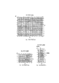
第1プログラム線図50aは、図3(a)に表したように、撮影画面の明るさを表す輝度(BV)に対応付けて、閃光装置13の発光期待値及び撮像素子3のISO感度のパラメータ(CV)と、露出値(EV)とが設定されている。第1プログラムでは、例えば、BVが−7の際に、EV7、CV14に設定される。
As shown in FIG. 3A, the first program diagram 50a is associated with the luminance (BV) representing the brightness of the shooting screen, and the expected light emission value of the
第2プログラム線図50bは、図3(b)に表したように、露出値(EV)に対応付けて、シャッター6の速度(TV)とIris3の絞り値(AV)とが設定されている。第2プログラム線図では、例えば、EV7の際に、TV5、AV2に設定される。
In the second program diagram 50b, as shown in FIG. 3B, the speed (TV) of the
第3プログラム線図50cは、図3(c)に表したように、閃光装置13の発光期待値及び撮像素子3のISO感度のパラメータ(CV)に対応付けて、撮像装置1のISO感度(SV)と閃光装置の発光期待値(LV)とが設定されている。第3プログラム線図50cでは、例えば、CV14の際に、SV5、LV9に設定される。第3プログラム線図50cでは、CVが5〜10の範囲で、ストロボ優先(LV優先)とISO感度優先(SV優先)とを選択できるように構成されている。
Third program diagram 50c is, as shown in FIG. 3 (c), in association with parameters of emission expectation and ISO sensitivity of the
また、図4に表したように、正規化係数Pdに対応付けて、ISO感度(SV)と閃光装置の発光期待値(LV)との割合が補正される。
Further, as shown in FIG. 4, the ratio between the ISO sensitivity (SV) and the expected light emission value (LV) of the flash device is corrected in association with the normalization coefficient Pd .
詳しくは、輝度座標毎(所謂、一単位毎に相当する)の距離の平均値(DVave)を求め、次いで、(式8)を用いて、この平均値(DVave)と一単位毎の距離との差分値の絶対値を求め、次いで、この絶対値の合計値を一単位の数N(つまり、平均値を求めた際の輝度座標の数である)で除算して正規化係数Pdを算出し、この正規化係数Pdに基づいて、第3プログラム線図におけるISO感度(SV)と閃光装置の発光期待値(LV)との割合を補正する。
(式8) Pd=((SUM|DV(h,v)−DVave|)/N)/Md
(式8)において、Mdは、正規化のための最大偏差係数であって、正規化係数Pdが最大1になるように設定される。また、(式8)におけるSUMは、集合和を求める演算記号である。
Specifically, the average value (DVave ) of the distance for each luminance coordinate (so-called so-called unit ) is obtained, and then the average value (DVave) and the distance per unit are calculated using (Equation 8). Then, the absolute value of the difference value is calculated , and then the total value of the absolute values is divided by a unit number N (that is, the number of luminance coordinates when the average value is calculated ) to calculate the normalization coefficient Pd. Then, based on the normalization coefficient Pd, the ratio between the ISO sensitivity (SV) and the expected light emission value (LV) of the flash device in the third program diagram is corrected.
(Formula 8) Pd = ((SUM | DV (h, v) −DVave |) / N) / Md
In (Expression 8), Md is a maximum deviation coefficient for normalization, and is set so that the normalization coefficient Pd becomes 1 at maximum. In addition, SUM in (Equation 8) is an operation symbol for obtaining a set sum.
そして、図4に表したように、例えば、補正前の座標がP0であって算出された正規化係数がPdの際に、CV線に沿ってPdの分だけ座標をシフトさせ、P1の座標が補正後の座標となる。この際、P0〜P2までの値を1(最大偏差係数である)とする。これにより、撮影画面における距離の偏差が大きいほど、閃光装置13の発光を抑えてISO感度を上げるように補正される。なお、本発明における閃光プログラム線図は、第1プログラム線図50a、第2プログラム線図50b、第3プログラム線図50c等によってその機能が発現される。
Then, as shown in FIG. 4, for example, when the coordinate before correction is P 0 and the calculated normalization coefficient is Pd, the coordinate is shifted by Pd along the CV line, and P1 The coordinates are the corrected coordinates. At this time, the values from P 0 to P 2 are set to 1 (the maximum deviation coefficient). As a result, the larger the distance deviation in the shooting screen is, the more the light is corrected by the
次に、第2露出生成部42bは、(式9)を用いて、反射率算出手段で算出された反射率(RVB)に応じて発光量を補正すると共に、第1露出生成部42aで補正されたP1の座標に対応付けて、閃光装置13の発光量GVsを算出する。つまり、第1露出生成部42aで設定されたLVsがSVと同一の空間座標における数値なので、これを閃光装置13のガイドナンバーに対応付けた発光値GVsに変換する。
(式9)
GVs=LOG2((2^(RVB+GVp+AVs−AVp+SVp−SVs)−2^(MV0+GVp+TVp−TVs))/(2^MV1−2^MV1−2^MV0))
Next, the second exposure generator 42b corrects the light emission amount according to the reflectance (RVB) calculated by the reflectance calculator using (Equation 9), and corrects it by the first exposure generator 42a. The light emission amount GVs of the
(Formula 9)
GVs = LOG 2 ((2 ^ (RVB + GVp + AVs-AVp + SVp-SVs) -2 ^ (MV0 + GVp + TVp-TVs)) / (2 ^ MV1-2 ^ MV1-2 ^ MV0))
(式9)において、RVBは反射率算出手段32で算出された被写体の反射率に基づく反射率の補正値、GVpは予備発光の際の閃光装置13のガイドナンバーのAPEX値である。GV、AV、SVに付与した添え字pが予備発光時に対応し、添え字sは本撮影時に対応する。また、MV0が予備発光なしの際の輝度の評価値、MV1が予備発光有りの際の輝度の評価値であって、LOG2(評価輝度値/目標輝度値)で算出される。
In (Equation 9), RVB is a reflectance correction value based on the reflectance of the subject calculated by the reflectance calculation means 32, and GVp is the APEX value of the guide number of the
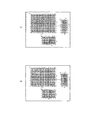
次に、図5、図6に基づいて、第1プログラム線図50a、第2プログラム線図50b、第3プログラム線図50cの作成手順について説明する。 Next, a procedure for creating the first program diagram 50a, the second program diagram 50b, and the third program diagram 50c will be described with reference to FIGS.
まず、図5(a)に表したように、予め、露出制御の範囲が定められている。AVの範囲がa〜b、TVの範囲がc〜d、EVの範囲が(a+c)〜(b+d)である。また、SVの範囲がe〜f、LVの範囲がg〜h、CVの範囲が(e+g)〜I、BVの範囲が((a+c)−I)〜((b+d)−(e+g))である。 First, as shown in FIG. 5A, a range of exposure control is determined in advance. The AV range is a to b, the TV range is c to d, and the EV range is (a + c) to (b + d). The SV range is e to f, the LV range is g to h, the CV range is (e + g) to I, and the BV range is ((a + c) -I) to ((b + d)-(e + g)). is there.
次に、図5(a)に定められた条件に対応付けて、図5(b)に表したようにBV線図にBVの範囲においてEV線とCV線を描き、図5(c)に表したようにEV線図にEVの範囲おいてTV線とAV線を描き、CV線図にCVの範囲においてSV線とLV線を描く。 Next, in association with the conditions defined in FIG. 5A, EV lines and CV lines are drawn in the range of BV on the BV diagram as shown in FIG. 5B, and FIG. As shown, a TV line and an AV line are drawn on the EV diagram in the range of EV, and an SV line and an LV line are drawn on the CV diagram in the range of CV.
次に、図6(d)に表したようにEV線図にAV及びTVの詳細な座標を入力し、CV線図にSV、LVの詳細な座標を入力する。また、図6(e)に表したようにBV線図にEV、CVの詳細な座標を入力する。 Next, as shown in FIG. 6D, detailed coordinates of AV and TV are input to the EV diagram, and detailed coordinates of SV and LV are input to the CV diagram. Further, as shown in FIG. 6E, detailed coordinates of EV and CV are input to the BV diagram.
次に、図7に基づいて、本実施例の撮像方法の手順を説明する。この手順は、CPU40がROM41に格納されたプログラムに基づいて、各機能部に指令信号を与えて実行する。また、図7におけるSは、ステップを表している。
Next, the procedure of the imaging method of the present embodiment will be described with reference to FIG. This procedure is executed by the
まず、この手順は、ユーザによって露出制御装置200に起動信号が入力された際にスタートする。
First, this procedure starts when an activation signal is input to the
次いで、図7に表したように、S100において、以前に演算された情報を初期化し、その後、S110に移る。 Next, as shown in FIG. 7, in S100, previously calculated information is initialized, and thereafter, the process proceeds to S110.
次いで、S110において、撮影条件に応じて、閃光装置13の予備発光の露出条件を設定し、その後、S120に移る。
Next, in S110, exposure conditions for preliminary light emission of the
次いで、S120において、基準距離検出手段14を用いて、撮影の際の特定領域の距離(DV(base))を取得し、その後、S130に移る。
Next, in S120, the distance (DV (base) ) of the specific area at the time of shooting is acquired using the reference
次いで、S130において、閃光装置14の予備発光無しに被写体を撮影し、その後、S140に移る。
Next, in S130, the subject is photographed without preliminary light emission from the
次いで、S140において、輝度信号生成手段21を用いて、隣接する水平2画素及び垂直2画素の4画素を一単位とする第1輝度信号(Ya(h,v))を生成し、これを4画素の中心に位置する輝度座標に対応付けて第1輝度バッファ23に保存し、その後、S150に移る。
Next, in S140, the luminance signal generation means 21 is used to generate a first luminance signal (Ya (h, v) ) having four pixels of two adjacent horizontal pixels and two vertical pixels as one unit. The information is stored in the
次いで、S150において、S110で設定された露出条件によって、閃光装置13を被写体に向けて発光(予備発光)して被写体を撮影し、その後、S160に移る。
Next, in S150, the
次いで、S160において、輝度信号生成手段21を用いて、隣接する水平2画素及び垂直2画素の4画素を一単位とする第2輝度信号(Yc(h,v))を生成し、これを4画素の中心に位置する輝度座標に対応付けて第2輝度バッファ24に保存し、その後、S170に移る。
Next, in S160, the luminance signal generating means 21 is used to generate a second luminance signal (Yc (h, v) ) having four pixels of two adjacent horizontal pixels and two vertical pixels as one unit. The brightness coordinates are stored in the
次いで、S170において、ストロボ光輝度算出手段25を用いて、輝度座標毎に、S160で生成した第2輝度信号(Yc(h,v))からS140で生成した第1輝度信号(Ya(h,v))を減算して、予備発光の際のストロボ光のみの輝度成分(Yb(h,v))を算出し、その後、S180に移る。 Next, in S170, the first luminance signal (Ya (h, v) ) generated in S140 from the second luminance signal (Yc (h, v) ) generated in S160 is used for each luminance coordinate using the strobe light luminance calculation means 25 . v) ) is subtracted to calculate the luminance component (Yb (h, v) ) of only the strobe light at the time of preliminary light emission, and then the process proceeds to S180.
次いで、S180において、第1パラメータ算出部27を用いて、第1輝度信号Yaを第1の被写体距離を求める際の第1のパラメータ(MVa)に変換すると共に、第2パラメータ算出部28を用いて、ストロボ光のみの輝度成分Ybを第1の被写体距離を求める際の第2のパラメータ(MVb)に変換し、その後、S190に移る。
Next, in S180, the first
次いで、S190において、第1距離情報算出部29を用いて、第1、第2のパラメータ、S110において設定した予備発光の露出値にもとづき、輝度座標毎に第1の被写体距離(DX(h,v))を算出し、その後、S200に移る。
Next, in S190, the first distance
次いで、S200において、補正値算出部30を用いて、S120の特定領域における、距離の基準値と第1の被写体距離との差分(OFFSET)を算出して、第1の被写体距離の補正値を求め、その後、S210に移る。
Next, in S200, the correction
次いで、S210において、第2距離情報算出部31を用いて、S190で算出した第1の被写体距離からS200で算出した補正値(OFFSET)を減算して、輝度座標毎に第2の被写体距離(DV(h,v))を算出し、その後、S220に移る。
Next, in S210, the second distance
次いで、S220において、反射率算出手段32を用いて、S110で設定した予備発光の露出値、S180で算出した第2のパラメータ、S210で算出した第2の被写体距離(DV(h,v))等、にもとづき、輝度座標毎に反射率情報(RV(h,v))を算出し、その後、S230に移る。
Next, in S220, using the reflectance calculation means 32, the exposure value of preliminary light emission set in S110, the second parameter calculated in S180, and the second subject distance (DV (h, v) ) calculated in S210. Based on the above, the reflectance information (RV (h, v) ) is calculated for each luminance coordinate, and then the process proceeds to S230.
次いで、S230において、記録手段33を用いて、第2の被写体距離(DV(h,v))及び反射率情報(RV(h,v))等を記録し、その後、S240に移る。
Next, in S230, the recording means 33 is used to record the second subject distance (DV (h, v) ), reflectance information (RV (h, v) ), etc., and then the process proceeds to S240.
次いで、S240において、第1露出生成部42aを用いて、撮影画面における距離偏差の正規化係数Pdを算出し、その後、S250に移る。 Next, in S240, the first exposure generator 42a is used to calculate the distance deviation normalization coefficient Pd in the shooting screen, and then the process proceeds to S250.
次いで、S250において、反射率算出手段32で算出された反射率を用いて、反射率の補正値RVBを生成し、その後、S260に移る。 Next, in S250, the reflectance correction value RVB is generated using the reflectance calculated by the reflectance calculating means 32, and then the process proceeds to S260.
その後、S260において、本撮影前のプレビュー画面の露出情報に基づいて、現在の明るさ情報のBV座標を算出し、その後、S270に移る。 Thereafter, in S260, the BV coordinates of the current brightness information are calculated based on the exposure information on the preview screen before the main photographing, and then the process proceeds to S270.
その後、S270において、第1露出生成部42a及び露出プログラム格納部50に備えられたプログラム線図を用いて、本撮影の際のシャッター速度(TV)、絞り値(AV)、ISO感度(SV)、及び、該プログラム線図上に対応する閃光装置の発光期待値(LV)等を設定し、さらに、輝度座標毎の距離の平均値(DVave)と輝度座標毎の距離との差分値の絶対値を求めて、この絶対値の合計を輝度座標の数で除算して正規化係数Pdを求め、正規化係数Pdに基づいて、プログラム線図上におけるISO感度(SV)と閃光装置の発光期待値(LV)との割合を補正し、その後、S280に移る。
After that, in S270, the shutter speed (TV), aperture value (AV), ISO sensitivity (SV) at the time of actual photographing are used using the program diagrams provided in the first exposure generator 42a and the
次いで、S280において、第2露出生成部42bを用いて、反射率補正値(RVB)に応じて発光量を補正すると共に、第1露出生成部42aで補正された発光期待値LVに対応付けて、閃光装置13の発光量GVsを算出し、本撮影の撮影条件とするGVs、TVs、AVs、SVsを設定する。
Next, in S280, the second exposure generation unit 42b is used to correct the light emission amount in accordance with the reflectance correction value (RVB) and to correspond to the expected light emission value LV corrected by the first exposure generation unit 42a. Then, the light emission amount GVs of the
次いで、S290において、オペレータからの指令信号に応じて、S280で設定された撮影条件に合わせて撮影し、本手順を終了する。 Next, in S290, according to the command signal from the operator, shooting is performed in accordance with the shooting conditions set in S280, and this procedure ends.
以上のように、本実施例に記載の撮像方法は、撮影画面において、所定の画素信号の数を一単位とする複数の輝度をマトリクス状に生成し、一単位毎に、撮像装置1から被写体までの距離DV(h,V)を検出し、次いで、撮影画面の明るさに応じて、閃光装置13の発光量を設定するプログラム線図を用いて閃光装置13の発光期待値(LV)を設定し、次いで、一単位毎(輝度座標毎)の距離の平均値を求めて、一単位毎に平均値(DVave)に対する距離の差分値の絶対値を求め、次いで、差分値の絶対値の合計を一単位の数(N)で除算して正規化係数Pdを算出し、算出された正規化係数Pdに基づいて、正規化係数Pdが大きくなるに従って閃光装置13の発光量を減少させて撮像素子8のISO感度を上げるように、閃光プログラム線図における発光期待値(LV)とISO感度(Sv)の割合を補正することにより、被写体と背景との距離差に応じて、適切に閃光装置13の発光量及び露出条件を設定できて利便性を向上できる。
As described above, the imaging method described in the present embodiment generates a plurality of luminances in the form of a matrix with the number of predetermined pixel signals as one unit on the shooting screen, and the subject from the
また、本実施例に記載の撮像方法は、第1プログラム線図50aによって発光量及びISO感度のパラメータ(CV)と露出値(EV)を設定し、次いで、第2プログラム線図50bによって露出値(EV)に応じたシャッター速度(TV)と絞り値(AV)とを設定し、第3プログラム線図50cによってISO感度(SV)と閃光装置の発光期待値(LV)とを設定できる。これにより、撮影画面に応じて、撮影の際のシャッター速度TV、絞り値AV、ISO感度SV、閃光装置13の発光量GV等を設定できて利便性を向上できる。
In the imaging method described in the present embodiment , the light emission amount and ISO sensitivity parameters (CV) and the exposure value (EV) are set by the first program diagram 50a, and then the exposure value by the second program diagram 50b. The shutter speed (TV) and aperture value (AV) corresponding to (EV) can be set, and the ISO sensitivity (SV) and the expected light emission value (LV) of the flash device can be set by the third program diagram 50c. Thereby, the shutter speed TV, aperture value AV, ISO sensitivity SV, light emission amount GV of the
また、本実施例に記載の撮像方法は、予備発光有無の画像データを取得して、撮影画面全体にマトリクス状に複数生成された輝度の座標に対応付けて、第2の被写体距離DV(h,v)を測定できる。
In addition, the imaging method described in the present embodiment acquires image data indicating whether or not preliminary light emission is performed, and associates the plurality of brightness coordinates generated in a matrix with the entire photographing screen, so that the second subject distance DV (h , V) can be measured.
また、本実施例に記載の撮像方法は、輝度座標毎の第2の被写体距離DV(h,v)に基づいて画成された画像領域同士の、相対的位置の差分を検出し、第2の被写体距離DV(h,v)によって区分された被写体部同士の相対的位置関係に係る情報に応じた調光が可能になり、一層、利便性を向上できる。
Further, the imaging method described in the present embodiment detects a relative position difference between image regions defined based on the second subject distance DV (h, v) for each luminance coordinate, Can be dimmed in accordance with information relating to the relative positional relationship between the subject portions divided by the subject distance DV (h, v) , and the convenience can be further improved.
以上、本発明の一実施例について説明したが、本発明は前記実施例に限定されるものでなく、各種の態様をとることができる。 As mentioned above, although one Example of this invention was described, this invention is not limited to the said Example, Various aspects can be taken.
本発明に係る撮像装置1及び撮像方法は、暗所で撮影する際の補助光としての閃光装置を備えた撮影に利用できる。
The
1…撮像装置、2…前部レンズ、3…Iris(絞り)、5…フォーカスレンズ、6…シャッター、7…フィルタ、8…撮像素子(CCD:Charge Coupled Devices)9…AFE(Analog Front End)、10…相関二重サンプリング回路(CDS:Corelated Double Sampling)、11…可変利得増幅器(AGC:Automatic Gain Control)、12…A/D変換器、13…閃光装置(例えば、ストロボである)、14…基準距離検出手段、15…Iris駆動部、16…検出部、16a…センサ、17…フォーカス駆動部、18…検出部、18a…センサ、19…TG(Timing Generator)、21…輝度信号生成手段、22…輝度バッファ、23…第1輝度バッファ、24…第2輝度バッファ、25…ストロボ光輝度算出手段、26…輝度座標距離情報生成手段、27…第1パラメータ算出部、28…第2パラメータ算出部、29…第1距離情報算出部、30…補正値算出部、31…第2距離情報算出部、32…反射率算出手段、33…記録手段、40…CPU(Central Processing Unit)、41…ROM(Read Only Memory)、42…撮影露出設定部、42a…第1露出生成部、42b…第2露出生成部、50…露出プログラム格納部、50a…第1プログラム線図、50b…第2プログラム線図、50c…第3プログラム線図、100…撮像部、200…露出制御装置。
DESCRIPTION OF
Claims (3)
撮影の際に、前記被写体に所定の光量の補助光を発光する閃光装置と、
撮影画面の明るさに応じて前記閃光装置の発光量及び前記撮像素子のISO感度を設定する閃光プログラム線図を用いる閃光プログラムと、
前記閃光プログラムを用いて前記被写体を撮影する際の入射光量を調節する露出制御部と、
を備えた撮像装置の撮像方法において、
前記光電変換素子の夫々から出力された画像信号を画素信号とした際に、前記撮影画面において、所定の画素信号の数を一単位とする複数の輝度をマトリクス状に生成し、前記一単位毎に、当該撮像装置から前記被写体までの距離を検出する距離情報検出手順と、
前記一単位毎の距離の平均値を求めて、前記一単位毎に前記平均値と前記被写体までの距離との差分値の絶対値を求め、次いで、該差分値の絶対値の合計を前記一単位の数で除算して正規化係数を算出し、該算出された正規化係数に基づいて、前記正規化係数が大きくなるに従って前記閃光装置の発光量を減少させて前記撮像素子のISO感度を上げるように、前記閃光プログラム線図における前記閃光装置の発光量と前記撮像素子のISO感度との割合を補正する露出生成手順と、
を用いることを特徴とする撮像方法。 An image sensor that has a plurality of photoelectric conversion elements arranged in a matrix and outputs image data of a subject imaged according to the amount of incident light;
A flash device that emits a predetermined amount of auxiliary light to the subject at the time of shooting;
A flash program using a flash program diagram for setting the light emission amount of the flash device and the ISO sensitivity of the image sensor in accordance with the brightness of the shooting screen;
An exposure controller that adjusts the amount of incident light when the subject is photographed using the flash program;
In an imaging method of an imaging apparatus comprising:
When the image signal output from each of the photoelectric conversion elements is used as a pixel signal, a plurality of luminances having a predetermined number of pixel signals as one unit are generated in a matrix on the photographing screen, and A distance information detection procedure for detecting a distance from the imaging device to the subject;
An average value of the distances for each unit is obtained, an absolute value of a difference value between the average value and the distance to the subject is obtained for each unit, and then the sum of the absolute values of the difference values is calculated as the one value. A normalization coefficient is calculated by dividing by the number of units, and based on the calculated normalization coefficient, the light emission amount of the flash device is decreased as the normalization coefficient increases, and the ISO sensitivity of the image sensor is increased. An exposure generation procedure for correcting a ratio between the light emission amount of the flash device and the ISO sensitivity of the image sensor in the flash program diagram,
An imaging method characterized by using.
前記閃光プログラム線図として、
前記撮影画面の明るさを表す輝度情報に対応付けて、前記発光量及び前記ISO感度のパラメータと前記露出制御部の露出値とを設定する第1プログラム線図と、
前記露出値に対応付けて、シャッター速度と絞り値とを設定する第2プログラム線図と、
前記発光量及び前記ISO感度のパラメータに対応付けて、前記撮像素子のISO感度と前記閃光装置の発光量とを設定する第3プログラム線図と、
を用いる、
ことを特徴とする請求項1に記載の撮像方法。 The imaging device includes a shutter and an aperture,
As the flash program diagram,
A first program diagram for setting the light emission amount and the ISO sensitivity parameter and the exposure value of the exposure control unit in association with luminance information representing the brightness of the shooting screen;
A second program diagram for setting a shutter speed and an aperture value in association with the exposure value;
A third program diagram for setting the ISO sensitivity of the image sensor and the light emission amount of the flash device in association with the parameters of the light emission amount and the ISO sensitivity;
Use
The imaging method according to claim 1, wherein:
前記距離情報検出手順が、
前記撮影画面の特定領域に対応する当該撮像装置から前記被写体までの距離の基準値を取得する基準距離取得手順と、
前記予備発光無しに撮影して得られた前記被写体の画像データに基づいて、所定の画素信号の数を一単位とする複数の第1輝度を、所定の画像領域にわたってマトリクス状に生成する第1輝度生成手順と、
前記予備発光して撮影して得られた前記被写体の画像データに基づいて、前記第1輝度と対になるように、前記所定の画素信号の数を一単位とする複数の第2輝度を生成する第2輝度生成手順と、
前記一単位毎に、前記第2輝度から前記第1輝度を減算して、前記予備発光の輝度成分を算出する輝度差算出手順と、
前記一単位毎に、前記第1輝度と、前記輝度差算出手順で算出された予備発光の輝度成分とを、夫々、所定の目標輝度と比較して該目標輝度との比を求め、この比を用いて、当該撮像装置から前記被写体までの第1の被写体距離を求める際の第1及び第2のパラメータを生成するパラメータ生成手順と、
前記第1及び第2のパラメータと、前記第2輝度生成手順における前記予備発光の際の露出値とに基づいて、前記一単位毎に、前記第1の被写体距離を生成する第1距離情報生成手順と、
前記特定領域に位置する前記第1の被写体距離と前記被写体距離の基準値との差分を算出してこの差分を補正値とする補正値算出手順と、
前記一単位毎に、前記補正値算出手順で生成された補正値を用いて、前記第1の被写体距離を補正し、第2の被写体距離を生成する第2距離情報生成手順と、
を用い、
前記パラメータ生成手順が、前記第1のパラメータをMVa、前記第2のパラメータをMVb、前記目標輝度をYt、前記第1輝度をYa、前記予備発光の輝度成分をYbと表した際に、前記第1のパラメータをMVa=LOG2(Ya/Yt)、前記第2のパラメータをMVb=LOG2(Yb/Yt)、の演算式で算出し、
前記第1距離情報生成手順が、前記第1の被写体距離のアペックス値をDX、前記第1輝度生成手順及び第2輝度生成手順における撮影の際のシャッタースピードのアペックス値をTV、前記閃光装置の予備発光のガイドナンバーのアペックス値をGVと表した際に、前記第1の被写体距離のアペックス値をDX=(MVa−MVb)/2−(5−TV−GV)/2、の演算式で算出し、
前記補正値算出手順が、前記補正値をOFFSET、前記特定領域における第1の被写体距離のアペックス値をDX(base)、前記特定領域における被写体距離の基準値のアペックス値をDV(base)と表した際に、前記補正値をOFFSET=DX(base)−DV(base)、の演算式で算出し、
前記第2距離情報生成手順が、前記第2の被写体距離のアペックス値をDV、前記第1の被写体距離のアペックス値をDX、前記補正値をOFFSETと表した際に、前記第2の被写体距離のアペックス値をDV=DX−OFFSET、の演算式で算出することにより、前記一単位毎に前記第2の被写体距離を推定演算し、
前記一単位毎に、前記第2の被写体距離を、前記撮像装置から前記被写体までの距離として検出する、
ことを特徴とする請求項1又は請求項2に記載の撮像方法。
Pre-flash procedure for pre-flash before actual shooting
The distance information detection procedure includes:
A reference distance acquisition procedure for acquiring a reference value of the distance from the imaging device corresponding to the specific area of the shooting screen to the subject;
First, a plurality of first luminances having a predetermined number of pixel signals as a unit are generated in a matrix over a predetermined image area based on image data of the subject obtained by photographing without the preliminary light emission. Luminance generation procedure;
Based on the image data of the subject obtained by shooting with the preliminary light emission, a plurality of second luminances with the number of the predetermined pixel signals as one unit are generated so as to be paired with the first luminance. A second luminance generation procedure to:
A luminance difference calculating procedure for subtracting the first luminance from the second luminance for each unit to calculate a luminance component of the preliminary light emission;
For each unit, the first luminance and the luminance component of the preliminary light emission calculated in the luminance difference calculation procedure are respectively compared with a predetermined target luminance to obtain a ratio with the target luminance, and this ratio A parameter generation procedure for generating first and second parameters when determining a first subject distance from the imaging device to the subject,
First distance information generation for generating the first subject distance for each unit based on the first and second parameters and the exposure value at the time of the preliminary light emission in the second luminance generation procedure. Procedure and
A correction value calculation procedure for calculating a difference between the first object distance located in the specific area and a reference value of the object distance and using the difference as a correction value;
A second distance information generation procedure for correcting the first subject distance using the correction value generated in the correction value calculation procedure for each unit, and generating a second subject distance;
Use
When the parameter generation procedure represents the first parameter as MVa, the second parameter as MVb, the target luminance as Yt, the first luminance as Ya, and the preliminary emission luminance component as Yb, The first parameter is calculated with an arithmetic expression of MVa = LOG 2 (Ya / Yt), and the second parameter is calculated with MVb = LOG 2 (Yb / Yt).
In the first distance information generation procedure, the apex value of the first object distance is DX, the apex value of the shutter speed at the time of shooting in the first luminance generation procedure and the second luminance generation procedure is TV, and the flash device When the apex value of the guide number of the preliminary light emission is expressed as GV, the apex value of the first subject distance is calculated by the following equation: DX = (MVa−MVb) / 2− (5-TV−GV) / 2. Calculate
In the correction value calculation procedure, the correction value is OFFSET, the apex value of the first object distance in the specific area is DX (base) , and the apex value of the reference value of the object distance in the specific area is DV (base). The correction value is calculated by the following equation: OFFSET = DX (base) −DV (base)
When the second distance information generation procedure expresses the apex value of the second subject distance as DV, the apex value of the first subject distance as DX, and the correction value as OFFSET, the second subject distance The second subject distance is estimated and calculated for each unit by calculating the apex value of DV by the formula DV = DX−OFFSET,
Detecting the second subject distance as the distance from the imaging device to the subject for each unit;
The imaging method according to claim 1, wherein the imaging method is characterized.
Priority Applications (1)
| Application Number | Priority Date | Filing Date | Title |
|---|---|---|---|
| JP2009036478A JP4812846B2 (en) | 2009-02-19 | 2009-02-19 | Imaging apparatus and imaging method |
Applications Claiming Priority (1)
| Application Number | Priority Date | Filing Date | Title |
|---|---|---|---|
| JP2009036478A JP4812846B2 (en) | 2009-02-19 | 2009-02-19 | Imaging apparatus and imaging method |
Publications (3)
| Publication Number | Publication Date |
|---|---|
| JP2010191266A JP2010191266A (en) | 2010-09-02 |
| JP2010191266A5 JP2010191266A5 (en) | 2010-10-14 |
| JP4812846B2 true JP4812846B2 (en) | 2011-11-09 |
Family
ID=42817355
Family Applications (1)
| Application Number | Title | Priority Date | Filing Date |
|---|---|---|---|
| JP2009036478A Active JP4812846B2 (en) | 2009-02-19 | 2009-02-19 | Imaging apparatus and imaging method |
Country Status (1)
| Country | Link |
|---|---|
| JP (1) | JP4812846B2 (en) |
Cited By (1)
| Publication number | Priority date | Publication date | Assignee | Title |
|---|---|---|---|---|
| JP7340986B2 (en) | 2019-08-01 | 2023-09-08 | 不二サッシ株式会社 | fire safety grid |
Families Citing this family (1)
| Publication number | Priority date | Publication date | Assignee | Title |
|---|---|---|---|---|
| CN114520880B (en) * | 2020-11-18 | 2023-04-18 | 华为技术有限公司 | Exposure parameter adjusting method and device |
Family Cites Families (4)
| Publication number | Priority date | Publication date | Assignee | Title |
|---|---|---|---|---|
| JPH08278540A (en) * | 1995-02-10 | 1996-10-22 | Asahi Optical Co Ltd | Light emission controller |
| JP4222213B2 (en) * | 2004-01-16 | 2009-02-12 | カシオ計算機株式会社 | Camera device, photographing sensitivity setting program, and photographing sensitivity setting method |
| JP4615458B2 (en) * | 2006-03-08 | 2011-01-19 | 富士フイルム株式会社 | Exposure control method and imaging apparatus |
| JP4533860B2 (en) * | 2006-03-09 | 2010-09-01 | 富士フイルム株式会社 | Imaging apparatus and exposure control method |
-
2009
- 2009-02-19 JP JP2009036478A patent/JP4812846B2/en active Active
Cited By (1)
| Publication number | Priority date | Publication date | Assignee | Title |
|---|---|---|---|---|
| JP7340986B2 (en) | 2019-08-01 | 2023-09-08 | 不二サッシ株式会社 | fire safety grid |
Also Published As
| Publication number | Publication date |
|---|---|
| JP2010191266A (en) | 2010-09-02 |
Similar Documents
| Publication | Publication Date | Title |
|---|---|---|
| JP4757927B2 (en) | White balance adjusting device and white balance adjusting method | |
| US7483064B2 (en) | Imaging apparatus | |
| US8218036B2 (en) | Image sensing apparatus and control method therefor | |
| JP2010147816A5 (en) | ||
| US7486884B2 (en) | Imaging device and imaging method | |
| US9277135B2 (en) | Image-pickup apparatus, control method for the same, and non-transitory computer-readable storage medium | |
| JP5152260B2 (en) | Imaging device | |
| JP4300936B2 (en) | Imaging device | |
| JP4812846B2 (en) | Imaging apparatus and imaging method | |
| JP5970871B2 (en) | Electronic camera | |
| JP6736279B2 (en) | Imaging device, image processing device, and image processing method | |
| JP6393091B2 (en) | Imaging apparatus, control method therefor, program, and storage medium | |
| US8957990B2 (en) | Apparatus and method for compensating for back light of image | |
| JP4604112B2 (en) | Subject information measuring method, subject information measuring device, exposure control method, and exposure control device | |
| JP2012095219A (en) | Imaging apparatus and control method of the same | |
| JP6090565B2 (en) | Imaging apparatus, imaging method, and program | |
| JP4813439B2 (en) | Imaging apparatus and control method thereof | |
| JP6272006B2 (en) | Imaging apparatus, image processing method, and program | |
| US20080199171A1 (en) | Imaging device | |
| JP5292829B2 (en) | Imaging device | |
| JP5515541B2 (en) | Imaging device | |
| JP2010271507A (en) | Imaging device, exposure adjustment method, and program | |
| JP2001086396A (en) | Image-pickup device | |
| KR101713255B1 (en) | Device and method for making high dynamic range image | |
| JP2017034536A (en) | Image processing apparatus, image processing method, and program |
Legal Events
| Date | Code | Title | Description |
|---|---|---|---|
| A521 | Request for written amendment filed |
Free format text: JAPANESE INTERMEDIATE CODE: A523 Effective date: 20100805 |
|
| A621 | Written request for application examination |
Free format text: JAPANESE INTERMEDIATE CODE: A621 Effective date: 20100805 |
|
| A871 | Explanation of circumstances concerning accelerated examination |
Free format text: JAPANESE INTERMEDIATE CODE: A871 Effective date: 20100813 |
|
| A975 | Report on accelerated examination |
Free format text: JAPANESE INTERMEDIATE CODE: A971005 Effective date: 20101110 |
|
| A131 | Notification of reasons for refusal |
Free format text: JAPANESE INTERMEDIATE CODE: A131 Effective date: 20101207 |
|
| A521 | Request for written amendment filed |
Free format text: JAPANESE INTERMEDIATE CODE: A523 Effective date: 20110119 |
|
| A131 | Notification of reasons for refusal |
Free format text: JAPANESE INTERMEDIATE CODE: A131 Effective date: 20110510 |
|
| A521 | Request for written amendment filed |
Free format text: JAPANESE INTERMEDIATE CODE: A523 Effective date: 20110512 |
|
| TRDD | Decision of grant or rejection written | ||
| A01 | Written decision to grant a patent or to grant a registration (utility model) |
Free format text: JAPANESE INTERMEDIATE CODE: A01 Effective date: 20110816 |
|
| A01 | Written decision to grant a patent or to grant a registration (utility model) |
Free format text: JAPANESE INTERMEDIATE CODE: A01 |
|
| A61 | First payment of annual fees (during grant procedure) |
Free format text: JAPANESE INTERMEDIATE CODE: A61 Effective date: 20110823 |
|
| R150 | Certificate of patent or registration of utility model |
Ref document number: 4812846 Country of ref document: JP Free format text: JAPANESE INTERMEDIATE CODE: R150 Free format text: JAPANESE INTERMEDIATE CODE: R150 |
|
| FPAY | Renewal fee payment (event date is renewal date of database) |
Free format text: PAYMENT UNTIL: 20140902 Year of fee payment: 3 |
|
| R250 | Receipt of annual fees |
Free format text: JAPANESE INTERMEDIATE CODE: R250 |
|
| R250 | Receipt of annual fees |
Free format text: JAPANESE INTERMEDIATE CODE: R250 |
|
| R250 | Receipt of annual fees |
Free format text: JAPANESE INTERMEDIATE CODE: R250 |
|
| R250 | Receipt of annual fees |
Free format text: JAPANESE INTERMEDIATE CODE: R250 |
|
| R250 | Receipt of annual fees |
Free format text: JAPANESE INTERMEDIATE CODE: R250 |
|
| R250 | Receipt of annual fees |
Free format text: JAPANESE INTERMEDIATE CODE: R250 |
|
| S111 | Request for change of ownership or part of ownership |
Free format text: JAPANESE INTERMEDIATE CODE: R313113 |
|
| S531 | Written request for registration of change of domicile |
Free format text: JAPANESE INTERMEDIATE CODE: R313531 |
|
| R371 | Transfer withdrawn |
Free format text: JAPANESE INTERMEDIATE CODE: R371 |
|
| R370 | Written measure of declining of transfer procedure |
Free format text: JAPANESE INTERMEDIATE CODE: R370 |
|
| S111 | Request for change of ownership or part of ownership |
Free format text: JAPANESE INTERMEDIATE CODE: R313113 |
|
| S531 | Written request for registration of change of domicile |
Free format text: JAPANESE INTERMEDIATE CODE: R313531 |
|
| R350 | Written notification of registration of transfer |
Free format text: JAPANESE INTERMEDIATE CODE: R350 |
|
| R250 | Receipt of annual fees |
Free format text: JAPANESE INTERMEDIATE CODE: R250 |
|
| R250 | Receipt of annual fees |
Free format text: JAPANESE INTERMEDIATE CODE: R250 |
|
| R250 | Receipt of annual fees |
Free format text: JAPANESE INTERMEDIATE CODE: R250 |
|
| R250 | Receipt of annual fees |
Free format text: JAPANESE INTERMEDIATE CODE: R250 |