EP1577998A1 - Steuerbare AC/DC Netzadapter für batteriebetriebene Geräte - Google Patents
Steuerbare AC/DC Netzadapter für batteriebetriebene Geräte Download PDFInfo
- Publication number
- EP1577998A1 EP1577998A1 EP04006551A EP04006551A EP1577998A1 EP 1577998 A1 EP1577998 A1 EP 1577998A1 EP 04006551 A EP04006551 A EP 04006551A EP 04006551 A EP04006551 A EP 04006551A EP 1577998 A1 EP1577998 A1 EP 1577998A1
- Authority
- EP
- European Patent Office
- Prior art keywords
- signal
- adapter
- power
- electronic device
- feedback signal
- Prior art date
- Legal status (The legal status is an assumption and is not a legal conclusion. Google has not performed a legal analysis and makes no representation as to the accuracy of the status listed.)
- Withdrawn
Links
Images


Classifications
-
- H—ELECTRICITY
- H02—GENERATION; CONVERSION OR DISTRIBUTION OF ELECTRIC POWER
- H02J—CIRCUIT ARRANGEMENTS OR SYSTEMS FOR SUPPLYING OR DISTRIBUTING ELECTRIC POWER; SYSTEMS FOR STORING ELECTRIC ENERGY
- H02J7/00—Circuit arrangements for charging or depolarising batteries or for supplying loads from batteries
- H02J7/02—Circuit arrangements for charging or depolarising batteries or for supplying loads from batteries for charging batteries from ac mains by converters
-
- H—ELECTRICITY
- H02—GENERATION; CONVERSION OR DISTRIBUTION OF ELECTRIC POWER
- H02J—CIRCUIT ARRANGEMENTS OR SYSTEMS FOR SUPPLYING OR DISTRIBUTING ELECTRIC POWER; SYSTEMS FOR STORING ELECTRIC ENERGY
- H02J2207/00—Indexing scheme relating to details of circuit arrangements for charging or depolarising batteries or for supplying loads from batteries
- H02J2207/20—Charging or discharging characterised by the power electronics converter
Definitions
- the present invention relates to power management for battery powered devices, and more particularly, to a power management topology that includes an external AC/DC adapter that is controlled by battery charge controller associated with a portable device.
- AC adapters have two present designs:
- PWM circuitry and controllers including power switches and DC/DC converter circuitry such as Buck, flyback, boost, bridge, or other type of converter topology
- Battery Chargers in systems like notebook computers, cellular phones and PDA's are generally used to control battery charging and/or power distribution to a system.
- Battery chargers generally have three popular designs:
- FIG. 1 depicts a conventional power management topology for a portable device.
- the system includes a portable device 10 that includes one or more batteries 30 and one or more active systems 18, 20, and/or 22 coupled to an AC/DC adapter 12.
- the adapter 12 operates to deliver controlled power to both charge the batteries and power any systems coupled thereto.
- a battery charger circuit 14 is provided to provide regulated power (voltage and/or current) to the battery 30 based on, for example, battery charging current, battery voltage, and/or available power from the adapter 12.
- FIG. 1A a block diagram of a conventional battery charger circuit 14 is depicted.
- the charger generally includes a plurality of error amplifiers 34 that monitor battery voltage and/or current and generate an error signal if the battery voltage and/or current exceed some predetermined threshold. Additionally, an error amplifier may be included to monitor input power availability and generate an error signal if the available power from the adapter 12 is exceeded.
- the charger 14 also includes a PWM generator and controller 36. The error signals generated by the error amplifiers are received by the controller 36 and operate to adjust the duty cycle of the PWM generator. The PWM signal is supplied to power switches and DC/DC converter 38 to generate a regulated DC source for charging the batteries.
- the AC/DC adapter 12 includes a PWM generator and controller, and further includes power switches and a DC/DC converter to provide a regulated output power source.
- the adapter 12 and the charger 14 include a PWM generator and controller, power switches and a DC/DC converter.
- the present invention provides a power management topology that includes an external AC/DC adapter that is controlled by battery charge controller.
- the charge controller includes the error amplifiers to generate a feedback control signal, while the AC/DC adapter is modified to receive the control feedback signal to regulate the duty cycle of the PWM generator associated with the adapter.
- System exemplary embodiments include a power management topology for a portable electronic device, comprising a portable electronic device comprising a rechargeable battery and a charge controller comprising circuitry generating a feedback signal indicative of battery voltage and/or battery charging current.
- the topology also includes an external AC/DC adapter generating a DC source signal from an AC source, said adapter comprising a PWM generator generating a PWM signal and controller.
- the controller receives the feedback signal and adjusts the duty cycle of the PWM signal thereby adjusting the voltage and/or current value of the DC source signal.
- the present invention provides an AC/DC adapter comprising a PWM generator generating a PWM signal, a controller receiving a feedback signal generated by an external portable electronic device, and a DC/DC converter circuit generating a DC source signal.
- the controller adjusts the duty cycle of the PWM signal based on the feedback signal thereby adjusting the voltage and/or current value of the DC source signal.
- FIG. 2 depicts a block diagram of an exemplary power management topology according to the present invention.
- the topology of Figure 2 includes a system 10 powered by an AC/DC adapter 32.
- the adapter 32 is feedback enabled to receive one or more feedback control signals generated by the error amplifiers associated with the charger.
- the charger it is only necessary for the charger to include error amplifiers, and is thus generalized as a charge controller 24.
- the charge controller 24 includes a plurality of error amplifiers that monitor battery voltage and/or current and generate an error signal if the battery voltage and/or current exceed some predetermined threshold.
- an error amplifier may be included to monitor input power availability and generate an error signal based on the charging requirement of the battery balanced with the power requirement of the active system.
- error signals are generally defined herein as feedback control signals 26, and are used to adjust the duty cycle of a PWM generator.
- One such battery charger topology is disclosed in U.S. Application Serial No. 09/948,828 entitled “Voltage Mode, High Accuracy Battery Charger," now US Patent No. 6,498,461, assigned to the same Assignee, and hereby incorporated by reference in its entirety.
- feedback control signals are generated for battery voltage, battery charging current, and/or available power from the DC source to adjust the duty cycle of the PWM generator, thereby adjusting power delivered to the battery.
- Other charge topologies are well-known in the art, and all such battery charging circuits are deemed interchangeable and equivalent circuitry for the charge controller 24 of the present invention.
- a conventional switched mode power supply (SWPS) AC/DC adapter includes PWM circuitry (generator and controller), power switches and DC/DC converter circuitry for generating a constant DC source.
- the PWM controller of the AC/DC adapter is adapted to receive the feedback information generated by the charge controller 24 to adjust the DC output.
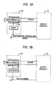
- Figures 3A, 3B and 3C depict exemplary communication topologies to facilitate communication between the charge controller 24 associated with the portable system 10 and the adapter 32 of the present invention.
- the adapter 32' is modified to include a serial communications interface 38 (e.g., RS232, RS434, Firewire, USB, etc.) to receive a serial control signal 26' generated by the charge controller.
- the feedback control signal generated by the charge control is converted into serial communication data and forwarded to the adapter 32'.
- the control signal 26" is an analog signal generated by the error amplifiers, and accordingly, an appropriate analog interface (e.g., buffer) may be provided in the adapter 32".
- Figure 3C does not utilize a separate control signal line, but rather, modulates the feedback signal 26'" onto the power line.
- both the adapter 32'" and system 10' are adapted with modulation/demodulation circuitry (42 and 44, respectively) to generate a feedback signal 26'" that is transposed on the power line.
- the present invention provides power management topologies that obviate the need for power circuitry associated with a conventional battery charger circuit, and instead utilize the power circuitry already present in an AC/DC adapter to generate regulated controllable power to charge a battery and/or power a portable device.
- the costs of power switches and power dissipation within the appliance have been eliminated.
- the cost of an additional controller has been eliminated.
- Printed circuit board space has been saved within the appliance as there is no need for bulky power switches.
- optimum charge algorithms can be implemented resulting in short battery charge times with full charge.
Priority Applications (1)
| Application Number | Priority Date | Filing Date | Title |
|---|---|---|---|
| EP04006551A EP1577998A1 (de) | 2004-03-18 | 2004-03-18 | Steuerbare AC/DC Netzadapter für batteriebetriebene Geräte |
Applications Claiming Priority (1)
| Application Number | Priority Date | Filing Date | Title |
|---|---|---|---|
| EP04006551A EP1577998A1 (de) | 2004-03-18 | 2004-03-18 | Steuerbare AC/DC Netzadapter für batteriebetriebene Geräte |
Publications (1)
| Publication Number | Publication Date |
|---|---|
| EP1577998A1 true EP1577998A1 (de) | 2005-09-21 |
Family
ID=34833643
Family Applications (1)
| Application Number | Title | Priority Date | Filing Date |
|---|---|---|---|
| EP04006551A Withdrawn EP1577998A1 (de) | 2004-03-18 | 2004-03-18 | Steuerbare AC/DC Netzadapter für batteriebetriebene Geräte |
Country Status (1)
| Country | Link |
|---|---|
| EP (1) | EP1577998A1 (de) |
Cited By (5)
| Publication number | Priority date | Publication date | Assignee | Title |
|---|---|---|---|---|
| WO2010057338A1 (zh) * | 2008-11-24 | 2010-05-27 | 克立欧电子有限公司 | 电源供应器用的输出电压反馈装置及该电源供应器 |
| US8686588B2 (en) | 2008-12-03 | 2014-04-01 | Fujitsu Technology Solutions Intellectual Property Gmbh | Device arrangement comprising an electronic device and a power adapter and method for connecting a power adapter |
| GB2514269A (en) * | 2009-06-23 | 2014-11-19 | Hewlett Packard Development Co | Power distribution to computer systems |
| GB2483420B (en) * | 2009-06-23 | 2015-02-18 | Hewlett Packard Development Co | Power distribution to computer systems |
| CN107005074A (zh) * | 2014-12-23 | 2017-08-01 | 英特尔公司 | 用于提供可选充电电压的装置和方法 |
Citations (5)
| Publication number | Priority date | Publication date | Assignee | Title |
|---|---|---|---|---|
| US5504454A (en) * | 1995-01-30 | 1996-04-02 | Westinghouse Elec. Corp. | Demodulator for powerline carrier communications |
| US5572110A (en) * | 1994-12-15 | 1996-11-05 | Intel Corporation | Smart battery charger system |
| US5684382A (en) * | 1996-07-19 | 1997-11-04 | Compaq Computer Corporation | Control of computer AC adapter output voltage via battery pack feedback |
| US6498461B1 (en) * | 2001-08-17 | 2002-12-24 | O2 Micro International Limited | Voltage mode, high accuracy battery charger |
| EP1447897A1 (de) * | 2003-02-11 | 2004-08-18 | O2 Micro, Inc. | Topologie eines Leistungsmanagements |
-
2004
- 2004-03-18 EP EP04006551A patent/EP1577998A1/de not_active Withdrawn
Patent Citations (5)
| Publication number | Priority date | Publication date | Assignee | Title |
|---|---|---|---|---|
| US5572110A (en) * | 1994-12-15 | 1996-11-05 | Intel Corporation | Smart battery charger system |
| US5504454A (en) * | 1995-01-30 | 1996-04-02 | Westinghouse Elec. Corp. | Demodulator for powerline carrier communications |
| US5684382A (en) * | 1996-07-19 | 1997-11-04 | Compaq Computer Corporation | Control of computer AC adapter output voltage via battery pack feedback |
| US6498461B1 (en) * | 2001-08-17 | 2002-12-24 | O2 Micro International Limited | Voltage mode, high accuracy battery charger |
| EP1447897A1 (de) * | 2003-02-11 | 2004-08-18 | O2 Micro, Inc. | Topologie eines Leistungsmanagements |
Cited By (9)
| Publication number | Priority date | Publication date | Assignee | Title |
|---|---|---|---|---|
| WO2010057338A1 (zh) * | 2008-11-24 | 2010-05-27 | 克立欧电子有限公司 | 电源供应器用的输出电压反馈装置及该电源供应器 |
| US8686588B2 (en) | 2008-12-03 | 2014-04-01 | Fujitsu Technology Solutions Intellectual Property Gmbh | Device arrangement comprising an electronic device and a power adapter and method for connecting a power adapter |
| GB2514269A (en) * | 2009-06-23 | 2014-11-19 | Hewlett Packard Development Co | Power distribution to computer systems |
| GB2514269B (en) * | 2009-06-23 | 2015-02-18 | Hewlett Packard Development Co | Power distribution to computer systems |
| GB2483420B (en) * | 2009-06-23 | 2015-02-18 | Hewlett Packard Development Co | Power distribution to computer systems |
| US9116676B2 (en) | 2009-06-23 | 2015-08-25 | Hewlett-Packard Development Company, L.P. | Power distribution to computer system |
| CN107005074A (zh) * | 2014-12-23 | 2017-08-01 | 英特尔公司 | 用于提供可选充电电压的装置和方法 |
| EP3238321A4 (de) * | 2014-12-23 | 2018-08-08 | Intel Corporation | Vorrichtung und verfahren zur bereitstellung einer wählbaren ladespannung |
| CN107005074B (zh) * | 2014-12-23 | 2021-07-06 | 英特尔公司 | 用于提供可选充电电压的装置和方法 |
Similar Documents
| Publication | Publication Date | Title |
|---|---|---|
| US6741066B1 (en) | Power management for battery powered appliances | |
| US20060291259A1 (en) | Power Management for Battery Powered Appliances | |
| CN102318175B (zh) | 具有自动模式切换的电力转换器 | |
| EP3312968B1 (de) | System und verfahren zur leistungsverwaltung | |
| US7679943B2 (en) | Uninterruptable power supply | |
| US8659263B2 (en) | Power supply circuit having low idle power dissipation | |
| JP5550785B2 (ja) | 非接触型の誘導電力伝送システムの回路 | |
| US7199552B2 (en) | Control circuit apparatus and power supply circuit control method | |
| US9973039B2 (en) | Power receiver, wireless power system and related method of transmitting information with a power receiver | |
| US20150069957A1 (en) | Reconfigurable compensator with large-signal stabilizing network | |
| US10170925B2 (en) | Intelligent uninterruptible power charging apparatus and method of operating the same | |
| US20090189571A1 (en) | High efficiency charging circuit and power supply system having such high efficiency charging circuit | |
| CN1252902A (zh) | 对一种电池供电的电子设备进行功率传输及电平转换 | |
| US11777338B2 (en) | AC switch PFC with integrated charger and DC-DC for online UPS systems | |
| EP1577998A1 (de) | Steuerbare AC/DC Netzadapter für batteriebetriebene Geräte | |
| US7755330B2 (en) | Methods and systems for controlling an AC adapter and battery charger in a closed loop configuration | |
| JP4202956B2 (ja) | バッテリ式電気器具のための電源管理 | |
| CN113890371A (zh) | 多输出的功率分配控制装置 | |
| KR100611871B1 (ko) | 배터리 전력 응용 기기를 위한 전력 관리 장치 및 방법 | |
| TW202030968A (zh) | 直流輸出不斷電電源供應器 | |
| CN114172377B (zh) | 具有电压输出调变的电源转换器 | |
| KR20240064101A (ko) | 무선 전력 수신 장치 및 그 동작 방법 |
Legal Events
| Date | Code | Title | Description |
|---|---|---|---|
| PUAI | Public reference made under article 153(3) epc to a published international application that has entered the european phase |
Free format text: ORIGINAL CODE: 0009012 |
|
| AK | Designated contracting states |
Kind code of ref document: A1 Designated state(s): AT BE BG CH CY CZ DE DK EE ES FI FR GB GR HU IE IT LI LU MC NL PL PT RO SE SI SK TR |
|
| AX | Request for extension of the european patent |
Extension state: AL LT LV MK |
|
| 17P | Request for examination filed |
Effective date: 20051109 |
|
| AKX | Designation fees paid |
Designated state(s): AT BE BG CH CY CZ DE DK EE ES FI FR GB GR HU IE IT LI LU MC NL PL PT RO SE SI SK TR |
|
| 17Q | First examination report despatched |
Effective date: 20051207 |
|
| STAA | Information on the status of an ep patent application or granted ep patent |
Free format text: STATUS: THE APPLICATION HAS BEEN WITHDRAWN |
|
| 18W | Application withdrawn |
Effective date: 20090528 |