EP1577918A2 - Device for detecting locally appearing overtemperatures - Google Patents
Device for detecting locally appearing overtemperatures Download PDFInfo
- Publication number
- EP1577918A2 EP1577918A2 EP05003813A EP05003813A EP1577918A2 EP 1577918 A2 EP1577918 A2 EP 1577918A2 EP 05003813 A EP05003813 A EP 05003813A EP 05003813 A EP05003813 A EP 05003813A EP 1577918 A2 EP1577918 A2 EP 1577918A2
- Authority
- EP
- European Patent Office
- Prior art keywords
- monitoring device
- switch
- switches
- insulating layer
- bimetallic
- Prior art date
- Legal status (The legal status is an assumption and is not a legal conclusion. Google has not performed a legal analysis and makes no representation as to the accuracy of the status listed.)
- Granted
Links
Images
Classifications
-
- H—ELECTRICITY
- H01—ELECTRIC ELEMENTS
- H01H—ELECTRIC SWITCHES; RELAYS; SELECTORS; EMERGENCY PROTECTIVE DEVICES
- H01H37/00—Thermally-actuated switches
-
- H—ELECTRICITY
- H01—ELECTRIC ELEMENTS
- H01H—ELECTRIC SWITCHES; RELAYS; SELECTORS; EMERGENCY PROTECTIVE DEVICES
- H01H37/00—Thermally-actuated switches
- H01H37/02—Details
- H01H37/32—Thermally-sensitive members
- H01H37/52—Thermally-sensitive members actuated due to deflection of bimetallic element
-
- H—ELECTRICITY
- H01—ELECTRIC ELEMENTS
- H01H—ELECTRIC SWITCHES; RELAYS; SELECTORS; EMERGENCY PROTECTIVE DEVICES
- H01H37/00—Thermally-actuated switches
- H01H37/74—Switches in which only the opening movement or only the closing movement of a contact is effected by heating or cooling
-
- H—ELECTRICITY
- H02—GENERATION; CONVERSION OR DISTRIBUTION OF ELECTRIC POWER
- H02H—EMERGENCY PROTECTIVE CIRCUIT ARRANGEMENTS
- H02H5/00—Emergency protective circuit arrangements for automatic disconnection directly responsive to an undesired change from normal non-electric working conditions with or without subsequent reconnection
- H02H5/04—Emergency protective circuit arrangements for automatic disconnection directly responsive to an undesired change from normal non-electric working conditions with or without subsequent reconnection responsive to abnormal temperature
- H02H5/047—Emergency protective circuit arrangements for automatic disconnection directly responsive to an undesired change from normal non-electric working conditions with or without subsequent reconnection responsive to abnormal temperature using a temperature responsive switch
Definitions
- the invention relates to a Üwachungsvortechnische for Detection of locally occurring excess temperatures.
- Such monitoring devices are in manifold Embodiments needed to attachments, devices and the like, especially among increased Temperatures are operated, ensure that in Case of malfunction or the like, resulting in a usually a local temperature rise can lead to Alarm triggered and in particular a shutdown of hazardous facilities.
- the invention is based on the object, such To create a monitoring device that is as simple as possible and therefore is constructed reliably working and the especially the possibility offers, even only locally reliably detect overheating occurring.
- a monitoring device solving this problem is characterized by one of an electrical Series connection of several bimetallic switches existing Switch arrangement, in which the bimetal switches below a selectable predetermined, design-related Switching temperature are closed and when exceeded switch the switching temperature to the opened state, wherein the bimetallic switches in linear, planar or also spatial form can be arranged and in their essentially fixed to each other mutual position are.
- the advantage achieved by the invention consists in essential in that in particular local Temperature increases are detected very reliably can, since already the triggering of a single Bimetallic switch is sufficient to the To let monitor to address. This happens by the fact that by the series arrangement of Bimetal switch is monitored for flowing current already interrupted, if only one of Bimetal switch opens.
- the bimetal switch a have irreversible switching behavior. Nevertheless it is also possible, the monitoring device with a self-holding relay circuit provided in comparably prevents a Reclosing can be done.
- the bimetallic switch over electrical cables connected together and together with this surrounded by an insulating layer. It can the Insulating layer formed by a hose or a pipe be; but there is also the possibility that the Insulating layer formed by a plastic extrusion is.
- Another embodiment is that the insulating layer of two the bimetal switch between formed receiving films. In such a Design also has the possibility that the electrical connections between the bimetallic switches formed on the foils applied conductor tracks are.
- a preferred application for the monitoring device exists in electrically heated containers, in particular Plastic containers for electroplating equipment, especially sensitive to overheating react. This is within the scope of the invention proposed that the switch assembly between the Heating elements and the wall of the container extends. On This way it is ensured that even if missing Liquid of galvanic bath or faulty Control behavior of the heater in good time a shutdown The heating elements can be done before these destructions on the plastic container wall cause.
- the electrical cables wear.
- the monitoring device can be linear or also be spread out like a sheet, here it is additionally can recommend that the switch assembly on is arranged well-conductive bodies. hereby will increase the sensitivity of the monitoring device additionally increased.
- the monitoring device shown in the drawing is used to detect locally occurring About temperatures.
- the bimetallic switches 1 are in linear, planar or spatial form arranged and in yet to be described in detail in their essentially fixed to each other mutual position.
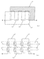
- a self-holding relay connected 2 in series the bimetallic switches 1, so that when opened once one of the switches 1 the relay contact drops and - even after re-closing the bimetallic switch 1 - do not wear again. This ensures that in In the event of an error, a check is first made can be. This can also be done in the same way be achieved that the bimetallic switch 1 a have irreversible switching behavior; then, however, is it is necessary to the triggered bimetallic switch 1 to replace.
- the bimetallic strips 1 are, as indicated in Figure 1, connected to each other via electrical cables 3 and surrounded with these by an insulating layer.
- the Insulating layer can be from a hose or a Be formed tube; there is also the possibility that the insulating layer of a plastic extrusion is formed.
- the bimetal switch is formed between receiving foils 4, as this is indicated in Figure 3, the electrical Connections 3 between the bimetallic switches 1 also of be formed on the sheets 4 printed conductors.
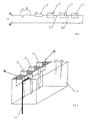
- FIG. 2 shows an application example for the Monitoring device shown in this electrically heated container 5 for galvanotechnische Monitored systems.
- This electrically heated container 5 for galvanotechnische Monitored systems.
- the switch assembly extends here conveniently between the heating elements 6 and the Wall of the container 5, so that excess temperatures too early a shutdown before damage to the Can enter the container wall.
- the monitoring device can also be used in the Range of cable trays 8 and cable channels be used, in which case again a individual design of the mutual arrangement of Bimetallic switch 1 is possible.
- the switch assembly also on good heat conducting Basic bodies be arranged so that - especially at long Cable Trays 8 - the number of monitors required bimetal switch 1 in appropriate sizes can be held.
Landscapes
- Physics & Mathematics (AREA)
- Thermal Sciences (AREA)
- Thermally Actuated Switches (AREA)
Abstract
Description
Die Erfindung betrifft eine Übewachungsvorrichtung zur Erfassung von lokal auftretenden Übertemperaturen.The invention relates to a Üwachungsvorrichtung for Detection of locally occurring excess temperatures.
Derartige Überwachungsvorrichtungen werden in vielfältigen Ausführungsformen benötigt, um bei Anlagen, Vorrichtungen und dergleichen, die insbesondere unter erhöhten Temperaturen betrieben werden, sicherzustellen, daß im Falle von Betriebsstörungen oder ähnlichem, die zu einem in der Regel lokalen Temperaturanstieg führen können, ein Alarm ausgelöst und insbesondere eine Abschaltung der gefährdenden Einrichtungen erfolgt.Such monitoring devices are in manifold Embodiments needed to attachments, devices and the like, especially among increased Temperatures are operated, ensure that in Case of malfunction or the like, resulting in a usually a local temperature rise can lead to Alarm triggered and in particular a shutdown of hazardous facilities.
Der Erfindung liegt die Aufgabe zugrunde, eine derartige Überwachungsvorrichtung zu schaffen, die möglichst einfach und daher zuverlässig arbeitend aufgebaut ist und die insbesondere die Möglichkeit bietet, auch nur lokal auftretende Überhitzungen zuverlässig zu erfassen.The invention is based on the object, such To create a monitoring device that is as simple as possible and therefore is constructed reliably working and the especially the possibility offers, even only locally reliably detect overheating occurring.
Eine diese Aufgabe lösende Überwachungsvorrichtung ist gekennzeichnet durch einen aus einer elektrischen Reihenschaltung von mehreren Bimetallschaltern bestehenden Schalteranordnung, bei der die Bimetallschalter unterhalb einer wählbar vorgebbaren, bauartbedingten Schalttemperatur geschlossen sind und bei Überschreitung der Schalttemperatur in den geöffneten Zustand umschalten, wobei die Bimetallschalter in linearer, flächenhafter oder auch räumlicher Form angeordnet sein können und in ihrer gegenseitigen Lage zueinander im wesentlichen fixiert sind.A monitoring device solving this problem is characterized by one of an electrical Series connection of several bimetallic switches existing Switch arrangement, in which the bimetal switches below a selectable predetermined, design-related Switching temperature are closed and when exceeded switch the switching temperature to the opened state, wherein the bimetallic switches in linear, planar or also spatial form can be arranged and in their essentially fixed to each other mutual position are.
Der durch die Erfindung erreichte Vorteil besteht im wesentlichen darin, daß insbesondere lokale Temperaturerhöhungen sehr zuverlässig erfasst werden können, da bereits das Auslösen eines einzigen Bimetallschalters ausreicht, um die Überwachungsvorrichtung ansprechen zu lassen. Dies geschieht dadurch, daß der durch die Reihenanordnung der Bimetallschalter fließende Strom überwacht wird, der bereits dann unterbrochen wird, wenn nur einer der Bimetallschalter öffnet. The advantage achieved by the invention consists in essential in that in particular local Temperature increases are detected very reliably can, since already the triggering of a single Bimetallic switch is sufficient to the To let monitor to address. This happens by the fact that by the series arrangement of Bimetal switch is monitored for flowing current already interrupted, if only one of Bimetal switch opens.
Um zu verhindern, daß nach einer Auslösung der Überwachungsvorrichtung und dem dadurch bedingten Abkühlen der die Auslösung verursachenden Störungsstelle ein möglicherweise unbeabsichtigtes Wiedereinschalten erfolgt, kann gemäß einer vorteilhaften Ausgestaltung der Erfindung vorgesehen sein, daß die Bimetallschalter ein irreversibles Schaltverhalten aufweisen. Gleichwohl ist es auch möglich, die Überwachungsvorrichtung mit einer selbsthaltenden Relaisschaltung zu versehen, die in vergleichbarer Weise verhindert, daß eine Wiedereinschaltung erfolgen kann.To prevent that after triggering the Monitoring device and the consequent cooling the fault causing the trip possibly unintentional restart occurs, can according to an advantageous embodiment of the invention be provided that the bimetal switch a have irreversible switching behavior. Nevertheless it is also possible, the monitoring device with a self-holding relay circuit provided in comparably prevents a Reclosing can be done.
Weiter besteht die Möglichkeit, mittels der erfindungsgemäßen Überwachungsvorrichtung auf unterschiedlich hohe kritische Temperaturen zu überwachen, in dem einzelne der in bestimmten Zonen angeordneten Bimetallschalter eine unterschiedliche Schalttemperatur aufweisen.Next there is the possibility of using the Monitoring device according to the invention monitor different high critical temperatures, in the individual arranged in certain zones Bimetal switch a different switching temperature exhibit.
In besonders einfacher und daher im Rahmen der Erfindung bevorzugter Ausgestaltung sind die Bimetallschalter über elektrische Kabel miteinander verbunden und zusammen mit diesen von einer Isolierschicht umgeben. Dabei kann die Isolierschicht von einem Schlauch oder einem Rohr gebildet sein; ebenso besteht jedoch auch die Möglichkeit, daß die Isolierschicht von einer Kunststoffumspritzung gebildet ist.In a particularly simple and therefore within the scope of the invention preferred embodiment, the bimetallic switch over electrical cables connected together and together with this surrounded by an insulating layer. It can the Insulating layer formed by a hose or a pipe be; but there is also the possibility that the Insulating layer formed by a plastic extrusion is.
Eine weitere Ausgestaltungsmöglichkeit besteht darin, daß die Isolierschicht von zwei die Bimetallschalter zwischen sich aufnehmenden Folien gebildet ist. Bei einer solchen Gestaltung besteht darüberhinaus die Möglichkeit, daß die elektrischen Verbindungen zwischen den Bimetallschaltern von auf den Folien aufgebrachten Leiterbahnen gebildet sind.Another embodiment is that the insulating layer of two the bimetal switch between formed receiving films. In such a Design also has the possibility that the electrical connections between the bimetallic switches formed on the foils applied conductor tracks are.
Eine bevorzugte Anwendung für die Überwachungsvorrichtung besteht bei elektrisch beheizten Behältern, insbesondere Behältern aus Kunststoff für galvanotechnische Anlagen, die in besonderem Maße empfindlich auf Überhitzungen reagieren. Hier wird im Rahmen der Erfindung vorgeschlagen, daß die Schalteranordnung sich zwischen den Heizelementen und der Wand der Behälter erstreckt. Auf diese Weise wird sichergestellt, daß auch bei fehlender Flüssigkeit des galvanischen Bades oder fehlerhaftem Regelverhalten der Heizung rechtzeitig eine Abschaltung der Heizelemente erfolgen kann, bevor diese Zerstörungen an der aus Kunststoff bestehenden Behälterwand verursachen.A preferred application for the monitoring device exists in electrically heated containers, in particular Plastic containers for electroplating equipment, especially sensitive to overheating react. This is within the scope of the invention proposed that the switch assembly between the Heating elements and the wall of the container extends. On This way it is ensured that even if missing Liquid of galvanic bath or faulty Control behavior of the heater in good time a shutdown The heating elements can be done before these destructions on the plastic container wall cause.
Bei derartigen Vorrichtungen können jedoch auch an Kontaktelementen, soweit diese durch Oxidation erhöhte Übergangswiderstände aufweisen, unbeabsichtigt hohe Temperaturen auftreten, so daß es sich empfiehlt, daß die Schalteranordnung auch im Bereich der den Galvanisierstrom übertragenden Kontakte verläuft.However, in such devices can also Contact elements, as far as they increased by oxidation Have contact resistance, unintentionally high Temperatures occur, so it is recommended that the Switch arrangement also in the area of the galvanizing passing contacts passes.
Eine weitere Anwendungsmöglichkeit besteht beispielsweise bei Kabeltrassen oder Kabelkanälen, die elektrische Kabel tragen. Je nach Anordnung und Auslegung dieser Kabeltrassen kann die Überwachungsvorrichtung linear oder auch flächenartig ausgebreitet sein, wobei es sich hier zusätzlich empfehlen kann, daß die Schalteranordnung auf gut wärmeleitenden Grundkörpern angeordnet ist. Hierdurch wird die Empfindlichkeit der Überwachungsvorrichtung zusätzlich erhöht. Another application is, for example in cable trays or cable ducts, the electrical cables wear. Depending on the arrangement and interpretation of this Cable trays, the monitoring device can be linear or also be spread out like a sheet, here it is additionally can recommend that the switch assembly on is arranged well-conductive bodies. hereby will increase the sensitivity of the monitoring device additionally increased.
Im folgenden wird die Erfindung an in der Zeichnung dargestellen Ausführungsbeispielen näher erläutert; es zeigen:
- Fig. 1
- den Anmeldungsgegenstand in einer schematischen Darstellung als Stromlaufplan,
- Fig. 2
- eine Anwendung der Überwachungsvorrichtung an einer galvanotechnischen Anlage,
- Fig. 3
- eine Ausgestaltung der Überwachungsvorrichtung zur Anwendung bei Kabeltrassen,
- Fig. 4
- eine detaillierte Darstellung des Anwendungsfalles nach Fig. 3.
- Fig. 1
- the subject of the application in a schematic representation as a circuit diagram,
- Fig. 2
- an application of the monitoring device to a galvanic plant,
- Fig. 3
- an embodiment of the monitoring device for use in cable trays,
- Fig. 4
- a detailed representation of the application of FIG. 3rd
Die in der Zeichnung dargestellte Überwachungsvorrichtung dient zur Erfassung von lokal auftretenden Übertemperaturen.The monitoring device shown in the drawing is used to detect locally occurring About temperatures.
Sie besteht im einzelnen aus einer elektrischen
Reihenschaltung von mehreren Bimetallschaltern 1, die
gemeinsam eine Schalteranordnung gemäß Figur 1 bilden. Die
Bimetallschalter 1 sind unterhalb einer entsprechend dem
Anwendungsfall wählbar vorgebbaren Schalttemperatur
geschlossen, wie dies in Figur 1 dargestellt ist.It consists in detail of an electrical
Series connection of several
Bei Überschreitung dieser Schalttemperatur gehen einer
oder mehrere der Bimetallschalter 1 in den geöffneten
Zustand über, wodurch der durch die Reihenschaltung der
Bimetallschalter fließende Strom unterbrochen wird.
Grundsätzlich bestünde hier auch die Möglichkeit, parallel
zu jedem Bimetallschalter 1 einen der Größe nach gleichen
Widerstand zu schalten; durch den Anstieg des
Durchlasswiderstandes beim Öffnen einer oder mehrerer
Schalter 1 könnte dann sogar ermittelt werden, ob es sich
nur um eine punktuelle oder flächenmäßig größere
Überhitzung handelt.When exceeding this switching temperature go one
or more of the
Die Bimetallschalter 1 sind dazu in linearer,
flächenhafter oder auch räumlicher Form angeordnet und in
noch im einzelnen zu beschreibender Weise in ihrer
gegenseitigen Lage zueinander im wesentlichen fixiert.The
Bei der in der Figur 1 dargestellten Schaltungsanordnung
liegt ein selbsthaltend beschaltetes Relais 2 in Reihe zu
den Bimetallschaltern 1, so daß bei einmaligem Öffnen
einer der Schalter 1 der Relaiskontakt abfällt und -
selbst nach dem erneuten Schließen des Bimetallschalters 1
- nicht wieder anzieht. Damit ist sichergestellt, daß in
einem Fehlerfall zunächst eine Überprüfung vorgenommen
werden kann. Dies kann in gleicher Weise auch dadurch
erreicht werden, daß die Bimetallschalter 1 ein
irreversibles Schaltverhalten aufweisen; dann jedoch ist
es erforderlich, den ausgelösten Bimetallschalter 1 zu
ersetzen.In the circuit arrangement shown in FIG
is a self-holding relay connected 2 in series
the
Sofern mit einer einzigen Überwachungsvorrichtung
verschiedene Bereiche auf unterschiedlich hohe
Temperaturen überwacht werden sollen, besteht auch die
Möglichkeit, daß die Bimetallschalter 1 entsprechend ihrer
Überwachungsaufgabe eine unterschiedliche Schalttemperatur
aufweisen. Unless with a single monitoring device
different areas at different heights
Temperatures are to be monitored, there is also the
Possibility that the
Die Bimetallschater 1 sind, wie in Figur 1 angedeutet,
über elektrische Kabel 3 miteinander verbunden und
zusammen mit diesen von einer Isolierschicht umgeben. Die
Isolierschicht kann dabei von einem Schlauch oder einem
Rohr gebildet sein; ebenso besteht auch die Möglichkeit,
daß die Isolierschicht von einer Kunststoffumspritzung
gebildet ist.The
Sofern die Isolierschicht von zwei die Bimetallschalter
zwischen sich aufnehmenden Folien 4 gebildet ist, wie dies
in Figur 3 angedeutet ist, so können die elektrischen
Verbindungen 3 zwischen den Bimetallschaltern 1 auch von
auf den Folien 4 aufgebrachten Leiterbahnen gebildet sein.Unless the insulating layer of two is the bimetal switch
is formed between receiving foils 4, as this
is indicated in Figure 3, the
In Figur 2 ist ein Anwendungsbeispiel für die
Überwachungsvorrichtung dargestellt, bei der diese
elektrisch beheizte Behälter 5 für galvanotechnische
Anlagen überwacht. Da Kunststoffbehälter im Gegensatz zu
Metallbehältern sensibel auf Temperaturerhöhungen
reagieren, ist hier eine zusätzliche Sicherung gegenüber
Übertemperaturen unumgänglich.FIG. 2 shows an application example for the
Monitoring device shown in this
electrically heated
Die Schalteranordnung erstreckt sich hier
zweckmäßigerweise zwischen den Heizelementen 6 und der
Wand der Behälter 5, so daß Übertemperaturen frühzeitig zu
einer Abschaltung führen, ehe eine Beschädigung der
Behälterwand eintreten kann.The switch assembly extends here
conveniently between the
Zusätzlich kann eine Überwachung auch im Bereich der den
Galvanisierstrom übertragenden Kontakte 7 verlaufen, da im
Falle einer schlechten elektrischen Verbindung, die zum
Beispiel durch eine Oxidation hervorgerufen werden kann,
eine erhöhte Verlustwärme am Kontakt 7 entsteht. Dies kann
im Extremfall ebenfalls zu Brandschäden führen.In addition, monitoring in the area of the
Schließlich kann die Überwachungsvorrichtung auch im
Bereich von Kabeltrassen 8 beziehungsweise Kabelkanälen
eingesetzt werden, wobei auch hier wiederum eine
individuelle Gestaltung der gegenseitigen Anordnung der
Bimetallschalter 1 möglich ist. Zusätzlich kann hier
jedoch die Schalteranordnung auch auf gut wärmeleitenden
Grundkörpern angeordnet sein, so daß - gerade bei langen
Kabeltrassen 8 - die Anzahl der zur Überwachung
erforderlichen Bimetallschalter 1 in angemessenen Größen
gehalten werden kann.Finally, the monitoring device can also be used in the
Range of
Claims (11)
Applications Claiming Priority (2)
| Application Number | Priority Date | Filing Date | Title |
|---|---|---|---|
| DE102004013805 | 2004-03-20 | ||
| DE102004013805A DE102004013805A1 (en) | 2004-03-20 | 2004-03-20 | Arrangement for detecting locally occurring excess temperatures |
Publications (3)
| Publication Number | Publication Date |
|---|---|
| EP1577918A2 true EP1577918A2 (en) | 2005-09-21 |
| EP1577918A3 EP1577918A3 (en) | 2007-08-01 |
| EP1577918B1 EP1577918B1 (en) | 2011-12-14 |
Family
ID=34833216
Family Applications (1)
| Application Number | Title | Priority Date | Filing Date |
|---|---|---|---|
| EP05003813A Expired - Lifetime EP1577918B1 (en) | 2004-03-20 | 2005-02-23 | Device for detecting locally appearing overtemperatures |
Country Status (3)
| Country | Link |
|---|---|
| EP (1) | EP1577918B1 (en) |
| AT (1) | ATE537544T1 (en) |
| DE (1) | DE102004013805A1 (en) |
Cited By (3)
| Publication number | Priority date | Publication date | Assignee | Title |
|---|---|---|---|---|
| EP2117284A1 (en) * | 2008-03-17 | 2009-11-11 | Martin Professional A/S | Safety loop for a light fixture |
| WO2011121080A1 (en) * | 2010-03-31 | 2011-10-06 | Phoenix Contact Gmbh & Co. Kg | Thermal fuse system for an electrical device |
| EP3605128A1 (en) * | 2018-08-03 | 2020-02-05 | Airbus Defence and Space | Electrical battery monitoring device and battery |
Families Citing this family (3)
| Publication number | Priority date | Publication date | Assignee | Title |
|---|---|---|---|---|
| DE102007025345B4 (en) * | 2007-05-31 | 2009-09-10 | Brose Fahrzeugteile GmbH & Co. Kommanditgesellschaft, Würzburg | Device for the protection of motor vehicle components |
| DE202010003613U1 (en) * | 2010-03-15 | 2011-08-05 | Voltwerk Electronics Gmbh | photovoltaic system |
| GB2554913A (en) * | 2016-10-13 | 2018-04-18 | John Fletcher Adam | Sensor apparatus for sending overheating |
Citations (1)
| Publication number | Priority date | Publication date | Assignee | Title |
|---|---|---|---|---|
| WO1993001640A1 (en) | 1991-07-02 | 1993-01-21 | Otter Controls Limited | Improvements relating to thermally-responsive controls |
Family Cites Families (3)
| Publication number | Priority date | Publication date | Assignee | Title |
|---|---|---|---|---|
| FR793477A (en) * | 1934-08-09 | 1936-01-24 | ||
| DE1038140B (en) * | 1954-02-12 | 1958-09-04 | Sueddeutsche Kabelwerke | Electric cable, in particular power cable, with a device for monitoring its operating temperature |
| DE19505541A1 (en) * | 1995-02-18 | 1996-08-22 | Wilo Gmbh | Bearing monitoring for electric motor |
-
2004
- 2004-03-20 DE DE102004013805A patent/DE102004013805A1/en not_active Withdrawn
-
2005
- 2005-02-23 EP EP05003813A patent/EP1577918B1/en not_active Expired - Lifetime
- 2005-02-23 AT AT05003813T patent/ATE537544T1/en active
Patent Citations (1)
| Publication number | Priority date | Publication date | Assignee | Title |
|---|---|---|---|---|
| WO1993001640A1 (en) | 1991-07-02 | 1993-01-21 | Otter Controls Limited | Improvements relating to thermally-responsive controls |
Cited By (8)
| Publication number | Priority date | Publication date | Assignee | Title |
|---|---|---|---|---|
| EP2117284A1 (en) * | 2008-03-17 | 2009-11-11 | Martin Professional A/S | Safety loop for a light fixture |
| CN101430080B (en) * | 2008-03-17 | 2011-04-06 | 马田专业公司 | Security circuit for electric lamp appliances |
| US7990673B2 (en) | 2008-03-17 | 2011-08-02 | Martin Professional A/S | Safety loop for a light fixture |
| EP2326150A3 (en) * | 2008-03-17 | 2011-12-21 | Martin Professional A/S | Safety loop for a light fixture |
| WO2011121080A1 (en) * | 2010-03-31 | 2011-10-06 | Phoenix Contact Gmbh & Co. Kg | Thermal fuse system for an electrical device |
| EP3605128A1 (en) * | 2018-08-03 | 2020-02-05 | Airbus Defence and Space | Electrical battery monitoring device and battery |
| US11378627B2 (en) | 2018-08-03 | 2022-07-05 | Airbus Helicopters Deutschland GmbH | Electrical battery monitoring device and battery |
| US11933852B2 (en) | 2018-08-03 | 2024-03-19 | Airbus Helicopters Deutschland GmbH | Electrical battery monitoring device and battery |
Also Published As
| Publication number | Publication date |
|---|---|
| EP1577918A3 (en) | 2007-08-01 |
| EP1577918B1 (en) | 2011-12-14 |
| DE102004013805A1 (en) | 2005-10-06 |
| ATE537544T1 (en) | 2011-12-15 |
Similar Documents
| Publication | Publication Date | Title |
|---|---|---|
| DE19809149A1 (en) | Security, in particular for automotive technology | |
| DE102005055325B3 (en) | Safety switching device for use in automated operation system, has switching arrangement determining operating voltage at connecting terminals, where arrangement is arranged to control output switching signal depending on operating voltage | |
| DE102009053146B3 (en) | Electrical equipment has housing, two conducting sections and connection component arranged within housing, where one end of conducting sections stands out as connection element from housing | |
| DE10036156A1 (en) | Circuit breaker for motor vehicle, has heating agent ignited in response to vehicle abnormality signal to melt retainer so that spring can extend to break circuit | |
| DE102018217743A1 (en) | Cable set for a charging station, charging station | |
| EP1577918A2 (en) | Device for detecting locally appearing overtemperatures | |
| DE102013224867B4 (en) | Electrical connection device and circuit arrangement and associated method | |
| WO2016075128A1 (en) | Relay comprising two current paths connected in parallel | |
| EP3853878B1 (en) | Fuse element and fuse | |
| DE102014207285B4 (en) | Method of power distribution and corresponding switch arrangement | |
| DE4401670A1 (en) | Control system for continuous flow fluid heater | |
| EP3771053A1 (en) | Arcing fault monitoring device, particularly for low-voltage switchgear | |
| EP2983191B1 (en) | Assembly for detecting electrical arcs in a low voltage network | |
| DE102017221937B4 (en) | Arrangement for electrical monitoring of the switching state of a fuse | |
| EP2019397A2 (en) | Electric transformer | |
| EP0620575B1 (en) | Installation to switch off a H.T. circuit | |
| DE10062280A1 (en) | Safety circuit for electrical and/or electronic control circuit for electrical device e.g. dishwasher, detects contact by liquid for protection of electrical device | |
| EP3400491B1 (en) | Saftey switching device and safety-related device | |
| DE102005022060A1 (en) | Monitoring system for e.g. generator of electrical power supply, has evaluation and monitoring electronics providing signal indicating interruption during occurrence of temperature difference at temperature sensors and change of difference | |
| EP4297055B1 (en) | Measuring module for a switchgear | |
| EP2553703B1 (en) | Thermal fuse system for an electrical device | |
| DE19844185A1 (en) | Bus line system, especially for controlling compact hydraulic drives as subscribers, has controller with external connection for connected subscriber with same characteristics as ring line | |
| EP2856592B1 (en) | Device for protecting a consumer from overloading and production method for a component of the device | |
| DE4020646C2 (en) | Protection circuit for the protection of electrical consumers | |
| EP2099048B1 (en) | Modular safety control and safety relay module |
Legal Events
| Date | Code | Title | Description |
|---|---|---|---|
| PUAI | Public reference made under article 153(3) epc to a published international application that has entered the european phase |
Free format text: ORIGINAL CODE: 0009012 |
|
| AK | Designated contracting states |
Kind code of ref document: A2 Designated state(s): AT BE BG CH CY CZ DE DK EE ES FI FR GB GR HU IE IS IT LI LT LU MC NL PL PT RO SE SI SK TR |
|
| AX | Request for extension of the european patent |
Extension state: AL BA HR LV MK YU |
|
| PUAL | Search report despatched |
Free format text: ORIGINAL CODE: 0009013 |
|
| AK | Designated contracting states |
Kind code of ref document: A3 Designated state(s): AT BE BG CH CY CZ DE DK EE ES FI FR GB GR HU IE IS IT LI LT LU MC NL PL PT RO SE SI SK TR |
|
| AX | Request for extension of the european patent |
Extension state: AL BA HR LV MK YU |
|
| 17P | Request for examination filed |
Effective date: 20080123 |
|
| AKX | Designation fees paid |
Designated state(s): AT BE BG CH CY CZ DE DK EE ES FI FR GB GR HU IE IS IT LI LT LU MC NL PL PT RO SE SI SK TR |
|
| 17Q | First examination report despatched |
Effective date: 20100315 |
|
| GRAP | Despatch of communication of intention to grant a patent |
Free format text: ORIGINAL CODE: EPIDOSNIGR1 |
|
| GRAJ | Information related to disapproval of communication of intention to grant by the applicant or resumption of examination proceedings by the epo deleted |
Free format text: ORIGINAL CODE: EPIDOSDIGR1 |
|
| GRAP | Despatch of communication of intention to grant a patent |
Free format text: ORIGINAL CODE: EPIDOSNIGR1 |
|
| GRAS | Grant fee paid |
Free format text: ORIGINAL CODE: EPIDOSNIGR3 |
|
| GRAA | (expected) grant |
Free format text: ORIGINAL CODE: 0009210 |
|
| AK | Designated contracting states |
Kind code of ref document: B1 Designated state(s): AT BE BG CH CY CZ DE DK EE ES FI FR GB GR HU IE IS IT LI LT LU MC NL PL PT RO SE SI SK TR |
|
| RAP1 | Party data changed (applicant data changed or rights of an application transferred) |
Owner name: REICH, FRANZ Owner name: SCHNEIDER, HANS |
|
| REG | Reference to a national code |
Ref country code: GB Ref legal event code: FG4D Free format text: NOT ENGLISH |
|
| RIN1 | Information on inventor provided before grant (corrected) |
Inventor name: SCHNEIDER, HANS Inventor name: REICH, FRANZ |
|
| REG | Reference to a national code |
Ref country code: CH Ref legal event code: EP |
|
| REG | Reference to a national code |
Ref country code: CH Ref legal event code: NV Representative=s name: ISLER & PEDRAZZINI AG |
|
| REG | Reference to a national code |
Ref country code: IE Ref legal event code: FG4D |
|
| REG | Reference to a national code |
Ref country code: DE Ref legal event code: R096 Ref document number: 502005012221 Country of ref document: DE Effective date: 20120301 |
|
| REG | Reference to a national code |
Ref country code: NL Ref legal event code: VDEP Effective date: 20111214 |
|
| PG25 | Lapsed in a contracting state [announced via postgrant information from national office to epo] |
Ref country code: LT Free format text: LAPSE BECAUSE OF FAILURE TO SUBMIT A TRANSLATION OF THE DESCRIPTION OR TO PAY THE FEE WITHIN THE PRESCRIBED TIME-LIMIT Effective date: 20111214 |
|
| LTIE | Lt: invalidation of european patent or patent extension |
Effective date: 20111214 |
|
| PG25 | Lapsed in a contracting state [announced via postgrant information from national office to epo] |
Ref country code: GR Free format text: LAPSE BECAUSE OF FAILURE TO SUBMIT A TRANSLATION OF THE DESCRIPTION OR TO PAY THE FEE WITHIN THE PRESCRIBED TIME-LIMIT Effective date: 20120315 Ref country code: NL Free format text: LAPSE BECAUSE OF FAILURE TO SUBMIT A TRANSLATION OF THE DESCRIPTION OR TO PAY THE FEE WITHIN THE PRESCRIBED TIME-LIMIT Effective date: 20111214 Ref country code: SE Free format text: LAPSE BECAUSE OF FAILURE TO SUBMIT A TRANSLATION OF THE DESCRIPTION OR TO PAY THE FEE WITHIN THE PRESCRIBED TIME-LIMIT Effective date: 20111214 Ref country code: SI Free format text: LAPSE BECAUSE OF FAILURE TO SUBMIT A TRANSLATION OF THE DESCRIPTION OR TO PAY THE FEE WITHIN THE PRESCRIBED TIME-LIMIT Effective date: 20111214 |
|
| PG25 | Lapsed in a contracting state [announced via postgrant information from national office to epo] |
Ref country code: CY Free format text: LAPSE BECAUSE OF FAILURE TO SUBMIT A TRANSLATION OF THE DESCRIPTION OR TO PAY THE FEE WITHIN THE PRESCRIBED TIME-LIMIT Effective date: 20111214 |
|
| REG | Reference to a national code |
Ref country code: IE Ref legal event code: FD4D |
|
| PG25 | Lapsed in a contracting state [announced via postgrant information from national office to epo] |
Ref country code: BG Free format text: LAPSE BECAUSE OF FAILURE TO SUBMIT A TRANSLATION OF THE DESCRIPTION OR TO PAY THE FEE WITHIN THE PRESCRIBED TIME-LIMIT Effective date: 20120314 Ref country code: CZ Free format text: LAPSE BECAUSE OF FAILURE TO SUBMIT A TRANSLATION OF THE DESCRIPTION OR TO PAY THE FEE WITHIN THE PRESCRIBED TIME-LIMIT Effective date: 20111214 Ref country code: IE Free format text: LAPSE BECAUSE OF FAILURE TO SUBMIT A TRANSLATION OF THE DESCRIPTION OR TO PAY THE FEE WITHIN THE PRESCRIBED TIME-LIMIT Effective date: 20111214 Ref country code: IS Free format text: LAPSE BECAUSE OF FAILURE TO SUBMIT A TRANSLATION OF THE DESCRIPTION OR TO PAY THE FEE WITHIN THE PRESCRIBED TIME-LIMIT Effective date: 20120414 Ref country code: EE Free format text: LAPSE BECAUSE OF FAILURE TO SUBMIT A TRANSLATION OF THE DESCRIPTION OR TO PAY THE FEE WITHIN THE PRESCRIBED TIME-LIMIT Effective date: 20111214 Ref country code: SK Free format text: LAPSE BECAUSE OF FAILURE TO SUBMIT A TRANSLATION OF THE DESCRIPTION OR TO PAY THE FEE WITHIN THE PRESCRIBED TIME-LIMIT Effective date: 20111214 |
|
| BERE | Be: lapsed |
Owner name: SCHNEIDER, HANS Effective date: 20120228 Owner name: REICH, FRANZ Effective date: 20120228 |
|
| PG25 | Lapsed in a contracting state [announced via postgrant information from national office to epo] |
Ref country code: PT Free format text: LAPSE BECAUSE OF FAILURE TO SUBMIT A TRANSLATION OF THE DESCRIPTION OR TO PAY THE FEE WITHIN THE PRESCRIBED TIME-LIMIT Effective date: 20120416 Ref country code: PL Free format text: LAPSE BECAUSE OF FAILURE TO SUBMIT A TRANSLATION OF THE DESCRIPTION OR TO PAY THE FEE WITHIN THE PRESCRIBED TIME-LIMIT Effective date: 20111214 Ref country code: RO Free format text: LAPSE BECAUSE OF FAILURE TO SUBMIT A TRANSLATION OF THE DESCRIPTION OR TO PAY THE FEE WITHIN THE PRESCRIBED TIME-LIMIT Effective date: 20111214 |
|
| PG25 | Lapsed in a contracting state [announced via postgrant information from national office to epo] |
Ref country code: MC Free format text: LAPSE BECAUSE OF NON-PAYMENT OF DUE FEES Effective date: 20120229 |
|
| PLBE | No opposition filed within time limit |
Free format text: ORIGINAL CODE: 0009261 |
|
| STAA | Information on the status of an ep patent application or granted ep patent |
Free format text: STATUS: NO OPPOSITION FILED WITHIN TIME LIMIT |
|
| PG25 | Lapsed in a contracting state [announced via postgrant information from national office to epo] |
Ref country code: DK Free format text: LAPSE BECAUSE OF FAILURE TO SUBMIT A TRANSLATION OF THE DESCRIPTION OR TO PAY THE FEE WITHIN THE PRESCRIBED TIME-LIMIT Effective date: 20111214 |
|
| 26N | No opposition filed |
Effective date: 20120917 |
|
| REG | Reference to a national code |
Ref country code: FR Ref legal event code: ST Effective date: 20121031 |
|
| GBPC | Gb: european patent ceased through non-payment of renewal fee |
Effective date: 20120314 |
|
| PG25 | Lapsed in a contracting state [announced via postgrant information from national office to epo] |
Ref country code: IT Free format text: LAPSE BECAUSE OF FAILURE TO SUBMIT A TRANSLATION OF THE DESCRIPTION OR TO PAY THE FEE WITHIN THE PRESCRIBED TIME-LIMIT Effective date: 20111214 |
|
| PG25 | Lapsed in a contracting state [announced via postgrant information from national office to epo] |
Ref country code: BE Free format text: LAPSE BECAUSE OF NON-PAYMENT OF DUE FEES Effective date: 20120228 |
|
| REG | Reference to a national code |
Ref country code: DE Ref legal event code: R097 Ref document number: 502005012221 Country of ref document: DE Effective date: 20120917 |
|
| PG25 | Lapsed in a contracting state [announced via postgrant information from national office to epo] |
Ref country code: FR Free format text: LAPSE BECAUSE OF NON-PAYMENT OF DUE FEES Effective date: 20120229 Ref country code: GB Free format text: LAPSE BECAUSE OF NON-PAYMENT OF DUE FEES Effective date: 20120314 |
|
| PG25 | Lapsed in a contracting state [announced via postgrant information from national office to epo] |
Ref country code: ES Free format text: LAPSE BECAUSE OF FAILURE TO SUBMIT A TRANSLATION OF THE DESCRIPTION OR TO PAY THE FEE WITHIN THE PRESCRIBED TIME-LIMIT Effective date: 20120325 |
|
| PG25 | Lapsed in a contracting state [announced via postgrant information from national office to epo] |
Ref country code: FI Free format text: LAPSE BECAUSE OF FAILURE TO SUBMIT A TRANSLATION OF THE DESCRIPTION OR TO PAY THE FEE WITHIN THE PRESCRIBED TIME-LIMIT Effective date: 20111214 |
|
| PG25 | Lapsed in a contracting state [announced via postgrant information from national office to epo] |
Ref country code: TR Free format text: LAPSE BECAUSE OF FAILURE TO SUBMIT A TRANSLATION OF THE DESCRIPTION OR TO PAY THE FEE WITHIN THE PRESCRIBED TIME-LIMIT Effective date: 20111214 |
|
| PG25 | Lapsed in a contracting state [announced via postgrant information from national office to epo] |
Ref country code: LU Free format text: LAPSE BECAUSE OF NON-PAYMENT OF DUE FEES Effective date: 20120223 |
|
| PG25 | Lapsed in a contracting state [announced via postgrant information from national office to epo] |
Ref country code: HU Free format text: LAPSE BECAUSE OF FAILURE TO SUBMIT A TRANSLATION OF THE DESCRIPTION OR TO PAY THE FEE WITHIN THE PRESCRIBED TIME-LIMIT Effective date: 20050223 |
|
| PGFP | Annual fee paid to national office [announced via postgrant information from national office to epo] |
Ref country code: CH Payment date: 20160211 Year of fee payment: 12 |
|
| PGFP | Annual fee paid to national office [announced via postgrant information from national office to epo] |
Ref country code: AT Payment date: 20160211 Year of fee payment: 12 |
|
| PGFP | Annual fee paid to national office [announced via postgrant information from national office to epo] |
Ref country code: DE Payment date: 20160409 Year of fee payment: 12 |
|
| REG | Reference to a national code |
Ref country code: DE Ref legal event code: R119 Ref document number: 502005012221 Country of ref document: DE |
|
| REG | Reference to a national code |
Ref country code: CH Ref legal event code: PL |
|
| REG | Reference to a national code |
Ref country code: AT Ref legal event code: MM01 Ref document number: 537544 Country of ref document: AT Kind code of ref document: T Effective date: 20170223 |
|
| PG25 | Lapsed in a contracting state [announced via postgrant information from national office to epo] |
Ref country code: CH Free format text: LAPSE BECAUSE OF NON-PAYMENT OF DUE FEES Effective date: 20170228 Ref country code: LI Free format text: LAPSE BECAUSE OF NON-PAYMENT OF DUE FEES Effective date: 20170228 Ref country code: AT Free format text: LAPSE BECAUSE OF NON-PAYMENT OF DUE FEES Effective date: 20170223 |
|
| PG25 | Lapsed in a contracting state [announced via postgrant information from national office to epo] |
Ref country code: DE Free format text: LAPSE BECAUSE OF NON-PAYMENT OF DUE FEES Effective date: 20170901 |