EP1577786A1 - Serial/parallel data transformer module and related computer system - Google Patents
Serial/parallel data transformer module and related computer system Download PDFInfo
- Publication number
- EP1577786A1 EP1577786A1 EP04006549A EP04006549A EP1577786A1 EP 1577786 A1 EP1577786 A1 EP 1577786A1 EP 04006549 A EP04006549 A EP 04006549A EP 04006549 A EP04006549 A EP 04006549A EP 1577786 A1 EP1577786 A1 EP 1577786A1
- Authority
- EP
- European Patent Office
- Prior art keywords
- serial
- parallel data
- data transformer
- computer system
- port
- Prior art date
- Legal status (The legal status is an assumption and is not a legal conclusion. Google has not performed a legal analysis and makes no representation as to the accuracy of the status listed.)
- Withdrawn
Links
Images


Classifications
-
- G—PHYSICS
- G06—COMPUTING OR CALCULATING; COUNTING
- G06F—ELECTRIC DIGITAL DATA PROCESSING
- G06F13/00—Interconnection of, or transfer of information or other signals between, memories, input/output devices or central processing units
- G06F13/38—Information transfer, e.g. on bus
- G06F13/40—Bus structure
- G06F13/4004—Coupling between buses
- G06F13/4027—Coupling between buses using bus bridges
Definitions
- the present invention relates to a serial/parallel data transformer module including a plurality of serial/parallel data transformers and a control unit capable of controlling the serial/parallel data transformer module to selectively operate in different modes according to the pre-characterizing clause of claim 1.
- a UART is a kind of asynchronous serial/parallel data transformer including a microchip for controlling data transmission between a computer (or a processor) and serial devices connected to the computer (or the processor). More clearly, the functions provided by the UART to the computer is similar to data exchange function provided by data terminal equipment (DTE) such as RS-232 so that the computer can exchange data with a serial device such as a modem via a serial bus such as a universal serial bus (USB).
- DTE data terminal equipment
- RS-232 serial terminal equipment
- USB universal serial bus
- one or more processors are generally installed in a computer system in order to speed up data processing. Accordingly, two UARTs are installed in the computer system for data exchange between the two processors and other serial devices. However, the two processors in the computer system can only be respectively connected to the two UARTs to exchange data with each one single serial device.
- the present invention aims at providing a serial/parallel data transformer module and a related computer system.
- the claimed serial/parallel data transformer module can allow a single processor to exchange data with two serial devices simultaneously, each processor to exchange data with a different serial device simultaneously, two processors to exchange data with each other, and two serial devices to exchange data with each other. Moreover, even two processors having different operational voltages can exchange data with each other by converting the level of the frame data transmitted or received by the two processors by means of the level shifter.
- a UART is a kind of asynchronous serial/parallel data transformer including a microchip for controlling data transmission between a computer (or a processor) and serial devices connected to the computer (or the processor). More clearly, the functions provided by the UART to the computer is similar to data exchange function provided by data terminal equipment (DTE) such as RS-232 so that the computer can exchange data with a serial device such as a modem via a serial bus such as a universal serial bus (USB).
- DTE data terminal equipment
- RS-232 serial terminal equipment
- USB universal serial bus
- the UART system 10 includes a system bus 26 allowing parallel data transmission, a processor 20 electrically connected to the system bus 26 for transmitting and receiving parallel data, a UART 22 for exchanging parallel data with serial data, a USB (or GSB, General Serial Bus) 28 allowing serial data transmission, and a serial device 24 electrically connected to the USB (GSB) 28 for transmitting and receiving serial data.
- a system bus 26 allowing parallel data transmission
- a processor 20 electrically connected to the system bus 26 for transmitting and receiving parallel data
- a UART 22 for exchanging parallel data with serial data
- a USB (or GSB, General Serial Bus) 28 allowing serial data transmission
- a serial device 24 electrically connected to the USB (GSB) 28 for transmitting and receiving serial data.
- the UART 22 includes six 8-bit registers 12 for storing control and status information, a baud rate generator 16 for determining the baud rate between the processor 20 and the serial device 24, a bus interface 14 electrically connected between the system bus 26 and the UART 22, and a transceiver 18 electrically connected to the serial device 24 for receiving and transmitting frame data.
- the bus interface 14 utilizes eight parallel pins to access data within the processor 20 via the system bus 26
- the transceiver 18 utilizes two pins (RxD for input and TxD for output) to access data within the serial device 24 via the USB (GSB) 28.
- the frame data includes an initial bit (space, logic "0") and an ending bit (mark, logic "1”) with the option to include a parity bit for error correction code (ECC).
- ECC error correction code
- the UART 22 serves to transfer data between the processor 20 and the serial device 24.
- the UART 22 transforms data transmitted in parallel by the processor 20 via the system bus 26 into the frame data by attaching an initial bit and an ending bit (and a parity bit if applicable) to the parallel data according to the control and status information stored in the register 12.
- the UART 22 then transmits the frame data to the serial device 24 bit by bit via the USB (GSB) 28.
- the UART 22 transforms the frame data transmitted bit by bit by the serial device 24 via the USB (GSB) 28 into parallel data.
- the UART 22 transmits the data in parallel to the processor 20 via the system bus 26 by checking and then discarding the parity bit (if a parity bit is attached) and stripping both the initial bit and ending bit.
- one or more processors are generally installed in a computer system in order to speed up data processing. Accordingly, two UARTs are installed in the computer system for data exchange between the two processors and other serial devices. However, the two processors in the computer system can only be respectively connected to the two UARTs to exchange data with each one single serial device.
- the serial/parallel data transformer further includes I 2 C (inter-IC), USB (Universal Serial Bus), SPI (Serial Peripheral Interface), SSP (Synchronous Serial Protocol), Microwire and I 2 S (Inter IC Sound) etc.
- I 2 C is connected between two ICs to transmit data between them via two bilateral (transmitting and receiving) transmission lines (serial data line SDA and serial clock line SCL).
- the serial/parallel data transformer module according to the present invention includes at least two identical serial/parallel data transformers. Since the data transformation of I 2 C, USB, SPI, SSP, Microwire and I 2 S are similar to that of UART, only the UART is described in the following description example.
- the UART module 30 can be an application specific integrated circuit (ASIC); that is, all the devices within the UART module 30 are integrated in the ASIC.
- the UART ASIC 30 includes a first UART 32, a second UART 34, and a control unit 36 for controlling the connection between the first UART 32 and the second UART 34 or between the UART and a parallel device such as a processor or a serial device such as a modem.
- the first UART 32 includes a first parallel port 38 (electrically connected to the bus interface 14 within the UART 22 shown in Fig.1) and a first serial port 40 (electrically connected to the transceiver 18 within the UART 22 shown in Fig.1);
- the second UART 34 includes a second parallel port 42 and a second serial port 44.
- the UART 22 shown in Fig.1 includes six 8-bit registers 12 for storing the control and status information.
- the UART 22 receives or transmits data according to the control and status information stored in the registers 12.
- the six registers are: an XMITDT register for storing 8-bit data to be transmitted by the transceiver 18, a RECVDT register for storing 8-bit data received by the transceiver 18, a DIVMSB register and a DIVLSB register for cooperatively storing a 16-bit (8 bits plus 8 bits) baud rate, a STATUS register for storing important information such as the current operation mode (transmitting or receiving data) of the UART 22, and a CLRINT register for remarking whether the data transmission and reception of the UART 22 is completed or not.
- the initial four low bits of the UART 22 are in sequence: an XMIT bit (bit 0, LSB) representing that the UART 22 is transmitting (also called under data transmission status) frame data, an RECV bit (bit 1) representing that the UART 22 is receiving (also called under data reception status) frame data, a DONE_XMIT bit (bit 2) representing that the UART 22 has completed transmitting the frame data, and a DONE_RECV bit (bit 3) representing that the UART 22 has completed receiving the frame data.
- the serial/parallel data transformer module i.e. UART module 30
- the computer system 50 further includes a first processor 52, a first system bus 53 for electrically connecting the first processor 52 to the UART ASIC 30, a second processor 54, a second system bus 55 for electrically connecting the second processor 54 to the UART ASIC 30, a first serial device 56, and a second serial device 58.
- switches SW 1 , SW 2 , SW 3 , SW 4 , SW 5 , SW 6 , SW 7 in the control unit 36 connect respectively node a and c, node a and e, node b and d 2 , node b and d 2 , node A and C, node B and E, node c and f.
- the first processor 52 can exchange data simultaneously with the first serial device 56 and the second serial device 58 via the UART ASIC 30 while the second processor 54 is idle.
- the lowest bit (XMIT bit) in the STATUS register of the six registers within the first UART 32 and the second UART 34 of the UART ASIC 30 will be determined as "1".
- the 8-bit data will have an initial bit and an ending bit attached to transform it into frame data so that it can be transmitted to the first serial device 56 and the second serial device 58.
- the RECV bit (bit 1) in the STATUS register will be determined as "1".
- the first processor 52 and the second processor 54 can exchange data respectively with the first serial device 56 and the second serial device 58.
- Fig.4 showing a second state of the computer system 50 according to the second embodiment of the present invention.
- the switches SW 1 , SW 2 , SW 3 , SW 4 , SW 5 , SW 6 , SW 7 in the control unit 36 connect respectively node a and c, node a and d 1 , node b and d 2 , node b and e, node A and C, node B and E, node c and f.
- the first processor 52 can exchange data with the first serial device 56 via the first UART 32 of the UART ASIC 30, and the second processor 54 can exchange data with the second serial device 58 via the second UART 34 of the UART ASIC 30.
- the first processor 52 and the second processor 54 can respectively transmit and receive data with the first serial device 56 and the second serial device 58.
- the processors (the first processor 52 and the second processor 54) exchange data with serial devices (the first serial device 56 and the second serial device 58); however, data exchange between the processors is also needed.
- Fig.5 showing a third state of the computer system 50 according to the second embodiment of the present invention.
- the switches SW 1 , SW 2 , SW 3 , SW 4 , SW 5 , SW 6 , SW 7 in the control unit 36 connect respectively node a and c, node a and d 1 , node b and d 2 , node b and e, node A and D, node B and D, node c and f.
- the first processor 52 can exchange data with the second processor 54 via the first UART 32 and the second UART 34 of the UART ASIC 30.
- the lowest bit (XMIT bit) in the STATUS register of the six registers within the first UART 32 will be determined as "1" in order to send out the frame data transformed from the 8-bit data
- the RECV bit (bit 1) in the STATUS register of the six registers within the second UART 34 will be determined as "1" in order to receive the frame data from the first UART 32 (essentially, connecting the Tx end of the first UART 32 for transmitting data with the Rx end of the second UART 34 for receiving data).
- the lowest bit (XMIT bit) in the STATUS register of the six registers within the second UART 34 will be determined as "1" in order to send out the frame data transformed from the 8-bit data and the RECV bit (bit 1) in the STATUS register of the six registers within the first UART 32 will be determined as "1" in order to receive the frame data from the second UART 34.
- Fig.6 showing the connection between the first processor 52, the second processor 54, the first UART 32, and the second UART 34 in the third state of the computer system 50 shown in Fig.5.
- the first UART 32 is controlled to respectively connect to the second UART 34 as a TX, RX, CTS, RTS, DSR, and DTR. That is, when the first processor 52 transmits 8-bit data to the second processor 54, the first UART 32 functions as a transmitter (TX), and the second UART 34 functions as a receiver.
- the second processor 54 transmits 8-bit data to the first processor 52, the first UART 32 functions as a receiver (RX), and the second UART 34 functions as a transmitter (RX).
- the first serial device 56 and the second serial device 58 in the computer system 50 can also exchange data with each other.
- Fig.7 showing a fourth state of the computer system 50 according to the second embodiment of the present invention.
- the switches SW 1 , SW 2 , SW 3 , SW 4 , SW 5 , SW 6 , SW 7 in the control unit 36 connect respectively node a and d 2 , node a and d 2 , node b and d 2 , node b and d 2 , node A and C, node B and E, node c and e.
- the first serial device 56 can exchange data with the second serial device 58 via the first UART 32 and the second UART 34.
- the RECV bit (bit 1) in the STATUS register of the six registers within the first UART 32 will be determined as "1" in order to receive the frame data from the first serial device 56, and the lowest bit (XMIT bit) in the STATUS register of the six registers within the second UART 34 will be determined as "1” in order to send out the frame data (transformed from 8-bit data which is transformed from the frame data by the first UART 32) to the second serial device 58.
- the same procedure applies in the case that the second serial device 58 transmits frame data to the first serial device 56.
- the first processor 52 and the second processor 54 is assumed to have the same operational voltage. However, in some computer systems having two processors, the operational voltage of the two processors may not be the same, meaning that data cannot be exchanged between two processors.
- FIG.8 showing a status of a computer system 80 according to the third embodiment of the present invention.
- a third processor 82 and a fourth processor 84 in the computer system 80 have different operational voltages (e.g. the operational voltage of the third processor 82 is 2.5v, and the operational voltage of the fourth processor 84 is 3.3v).
- the computer system 80 also includes a first serial device 56, a second serial device 58, a first system bus 53, a second system bus 55, and a UART ASIC 90.
- the UART ASIC 90 includes not only the first UART 32, the second UART 34, and a control unit 96 (the control unit 96 is different from the control unit 36 in that node e of the control unit 36 is replaced by node e 1 and e 2 in the control unit 96), but also a level shifter 98 electrically connected to node e 1 .
- switches SW 1 , SW 2 , SW 3 , SW 4 , SW 5 , SW 6 , SW 7 in the control unit 96 connect respectively node a and c, node a and d 1 , node b and d 2 , node b and e 1 , node A and D, node B and D, node c and f; the level shifter 98 converts the frame data output by the third processor 82 into a predetermined voltage. Then the first UART 32 transmits the converted frame data to the second UART 34 and the control unit 96. Afterwards, the level shifter 98 converts it into voltage level of the fourth processor 84. The same procedure applies when the frame data is output by the fourth processor 84 instead of the third processor 82. In such a manner, even if the operational voltages are different, the third processor 82 and the fourth processor 84 in the computer system 80 can exchange data.
- the level shifter 98 is located outside of the first UART 32 and the second UART 34.
- the level shifters in the serial/parallel data transformer module according to the present invention can be respectively installed in the first UART 32 and/or the second UART 34.
- the serial/parallel data transformer module can allow the following: a single processor to exchange data with two serial devices simultaneously, each processor to exchange data with a different serial device simultaneously, two processors to exchange data with each other, and two serial devices to exchange data with each other. Moreover, even two processors having different operational voltages can exchange data with each other by converting the level of the frame data transmitted or received by the two processors by means of the level shifter.
Landscapes
- Engineering & Computer Science (AREA)
- General Engineering & Computer Science (AREA)
- Theoretical Computer Science (AREA)
- Computer Hardware Design (AREA)
- Physics & Mathematics (AREA)
- General Physics & Mathematics (AREA)
- Information Transfer Systems (AREA)
Abstract
A serial/parallel data transformer module (30, 90) has a first serial/parallel data transformer (32) having a parallel port (38) and a serial port (40), a second serial/parallel data transformer (34) having a parallel port (42) and a serial port (44), and a control unit (36, 96) for selectively connecting the parallel ports (38, 42) or the serial ports (40, 44) of the first serial/parallel data transformer (32) and the second serial/parallel data transformer (34).
Description
The present invention relates to a serial/parallel data transformer module
including a plurality of serial/parallel data transformers and a control unit capable of
controlling the serial/parallel data transformer module to selectively operate in
different modes according to the pre-characterizing clause of claim 1.
Compared with synchronous parallel transmission, asynchronous serial
transmission has advantages such as low cost, long transmission distance, and
compactness in size. For instance, a UART is a kind of asynchronous serial/parallel
data transformer including a microchip for controlling data transmission between a
computer (or a processor) and serial devices connected to the computer (or the
processor). More clearly, the functions provided by the UART to the computer is
similar to data exchange function provided by data terminal equipment (DTE) such as
RS-232 so that the computer can exchange data with a serial device such as a modem
via a serial bus such as a universal serial bus (USB).
In recent years, one or more processors are generally installed in a computer
system in order to speed up data processing. Accordingly, two UARTs are installed in
the computer system for data exchange between the two processors and other serial
devices. However, the two processors in the computer system can only be respectively
connected to the two UARTs to exchange data with each one single serial device.
This in mind, the present invention aims at providing a serial/parallel data
transformer module and a related computer system.
This is achieved by a computer system according to claim 1. The dependent
claims pertain to corresponding further developments and improvements.
As will be seen more clearly from the detailed description following below, the
claimed serial/parallel data transformer module can allow a single processor to
exchange data with two serial devices simultaneously, each processor to exchange
data with a different serial device simultaneously, two processors to exchange data
with each other, and two serial devices to exchange data with each other. Moreover,
even two processors having different operational voltages can exchange data with
each other by converting the level of the frame data transmitted or received by the two
processors by means of the level shifter.
In the following, the invention is further illustrated by way of example, taking
reference to the accompanying drawings. Thereof
Compared with synchronous parallel transmission, asynchronous serial
transmission has advantages such as low cost, long transmission distance, and
compactness in size. For instance, a UART is a kind of asynchronous serial/parallel
data transformer including a microchip for controlling data transmission between a
computer (or a processor) and serial devices connected to the computer (or the
processor). More clearly, the functions provided by the UART to the computer is
similar to data exchange function provided by data terminal equipment (DTE) such as
RS-232 so that the computer can exchange data with a serial device such as a modem
via a serial bus such as a universal serial bus (USB).
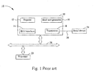
Please refer to Fig.1 showing a block diagram of a conventional UART system
10. The UART system 10 includes a system bus 26 allowing parallel data
transmission, a processor 20 electrically connected to the system bus 26 for
transmitting and receiving parallel data, a UART 22 for exchanging parallel data with
serial data, a USB (or GSB, General Serial Bus) 28 allowing serial data transmission,
and a serial device 24 electrically connected to the USB (GSB) 28 for transmitting
and receiving serial data.
The UART 22 includes six 8-bit registers 12 for storing control and status
information, a baud rate generator 16 for determining the baud rate between the
processor 20 and the serial device 24, a bus interface 14 electrically connected
between the system bus 26 and the UART 22, and a transceiver 18 electrically
connected to the serial device 24 for receiving and transmitting frame data. Generally
in the UART 22, the bus interface 14 utilizes eight parallel pins to access data within
the processor 20 via the system bus 26, and the transceiver 18 utilizes two pins (RxD
for input and TxD for output) to access data within the serial device 24 via the USB
(GSB) 28. The frame data includes an initial bit (space, logic "0") and an ending bit
(mark, logic "1") with the option to include a parity bit for error correction code
(ECC).
The UART 22 serves to transfer data between the processor 20 and the serial
device 24. In the case of data being transferred from the processor 20 to the serial
device 24, the UART 22 transforms data transmitted in parallel by the processor 20
via the system bus 26 into the frame data by attaching an initial bit and an ending bit
(and a parity bit if applicable) to the parallel data according to the control and status
information stored in the register 12. The UART 22 then transmits the frame data to
the serial device 24 bit by bit via the USB (GSB) 28. In the case of data being
transferred from the serial device 24 to the processor 20, the UART 22 transforms the
frame data transmitted bit by bit by the serial device 24 via the USB (GSB) 28 into
parallel data. The UART 22 then transmits the data in parallel to the processor 20 via
the system bus 26 by checking and then discarding the parity bit (if a parity bit is
attached) and stripping both the initial bit and ending bit.
In recent years, one or more processors are generally installed in a computer
system in order to speed up data processing. Accordingly, two UARTs are installed in
the computer system for data exchange between the two processors and other serial
devices. However, the two processors in the computer system can only be respectively
connected to the two UARTs to exchange data with each one single serial device.
In addition to the UART (RS232 is a type of UART) mentioned above, the
serial/parallel data transformer further includes I2C (inter-IC), USB (Universal Serial
Bus), SPI (Serial Peripheral Interface), SSP (Synchronous Serial Protocol), Microwire
and I2S (Inter IC Sound) etc. I2C is connected between two ICs to transmit data
between them via two bilateral (transmitting and receiving) transmission lines (serial
data line SDA and serial clock line SCL).
The serial/parallel data transformer module according to the present invention
includes at least two identical serial/parallel data transformers. Since the data
transformation of I2C, USB, SPI, SSP, Microwire and I2S are similar to that of UART,
only the UART is described in the following description example.
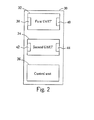
Please refer to Fig.2 showing a block diagram of a UART module 30 according
to the present invention. The UART module 30 can be an application specific
integrated circuit (ASIC); that is, all the devices within the UART module 30 are
integrated in the ASIC. The UART ASIC 30 includes a first UART 32, a second
UART 34, and a control unit 36 for controlling the connection between the first
UART 32 and the second UART 34 or between the UART and a parallel device such
as a processor or a serial device such as a modem. The first UART 32 includes a first
parallel port 38 (electrically connected to the bus interface 14 within the UART 22
shown in Fig.1) and a first serial port 40 (electrically connected to the transceiver 18
within the UART 22 shown in Fig.1); the second UART 34 includes a second parallel
port 42 and a second serial port 44. The control by the control unit 36 on the
connection between the first UART 32 and the second UART 34 or between the
UART and other parallel or serial devices is described in the following.
As mentioned above, the UART 22 shown in Fig.1 includes six 8-bit registers 12
for storing the control and status information. The UART 22 receives or transmits
data according to the control and status information stored in the registers 12. The six
registers are: an XMITDT register for storing 8-bit data to be transmitted by the
transceiver 18, a RECVDT register for storing 8-bit data received by the transceiver
18, a DIVMSB register and a DIVLSB register for cooperatively storing a 16-bit (8
bits plus 8 bits) baud rate, a STATUS register for storing important information such
as the current operation mode (transmitting or receiving data) of the UART 22, and a
CLRINT register for remarking whether the data transmission and reception of the
UART 22 is completed or not. The initial four low bits of the UART 22 are in
sequence: an XMIT bit (bit 0, LSB) representing that the UART 22 is transmitting
(also called under data transmission status) frame data, an RECV bit (bit 1)
representing that the UART 22 is receiving (also called under data reception status)
frame data, a DONE_XMIT bit (bit 2) representing that the UART 22 has completed
transmitting the frame data, and a DONE_RECV bit (bit 3) representing that the
UART 22 has completed receiving the frame data. The serial/parallel data transformer
module (i.e. UART module 30) according to the present invention changes data
transmission status between the first UART 32 and the second UART 34 or between
the UART and other parallel or serial devices by changing the control and status
information stored in the registers of the first UART 32 and the second UART 34.
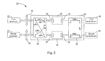
Please refer to Fig.3 showing a first state of a computer system 50 including the
UART ASIC 30 according to the second embodiment of the present invention. The
computer system 50 further includes a first processor 52, a first system bus 53 for
electrically connecting the first processor 52 to the UART ASIC 30, a second
processor 54, a second system bus 55 for electrically connecting the second processor
54 to the UART ASIC 30, a first serial device 56, and a second serial device 58. In the
second embodiment, switches SW1, SW2, SW3, SW4, SW5, SW6, SW7 in the control
unit 36 connect respectively node a and c, node a and e, node b and d2, node b and d2,
node A and C, node B and E, node c and f. With this setup, the first processor 52 can
exchange data simultaneously with the first serial device 56 and the second serial
device 58 via the UART ASIC 30 while the second processor 54 is idle. When the
first processor 52 transmits 8-bit data to the first serial device 56 and the second serial
device 58, the lowest bit (XMIT bit) in the STATUS register of the six registers
within the first UART 32 and the second UART 34 of the UART ASIC 30 will be
determined as "1". Of course, the 8-bit data will have an initial bit and an ending bit
attached to transform it into frame data so that it can be transmitted to the first serial
device 56 and the second serial device 58. In the case when the first processor 52
receives frame data from the first serial device 56 and the second serial device 58, the
RECV bit (bit 1) in the STATUS register will be determined as "1".
In the computer system 50, the first processor 52 and the second processor 54
can exchange data respectively with the first serial device 56 and the second serial
device 58. Please refer to Fig.4 showing a second state of the computer system 50
according to the second embodiment of the present invention. As shown in Fig.4, the
switches SW1, SW2, SW3, SW4, SW5, SW6, SW7 in the control unit 36 connect
respectively node a and c, node a and d1, node b and d2, node b and e, node A and C,
node B and E, node c and f. In this setup, the first processor 52 can exchange data
with the first serial device 56 via the first UART 32 of the UART ASIC 30, and the
second processor 54 can exchange data with the second serial device 58 via the
second UART 34 of the UART ASIC 30. By setting the value of the respective
corresponding STATUS register in the first UART 32 and the second UART 34, the
first processor 52 and the second processor 54 can respectively transmit and receive
data with the first serial device 56 and the second serial device 58.
In the computer system 50 described above, the processors (the first processor 52
and the second processor 54) exchange data with serial devices (the first serial device
56 and the second serial device 58); however, data exchange between the processors
is also needed. Please refer to Fig.5 showing a third state of the computer system 50
according to the second embodiment of the present invention. In the computer system
50 shown in Fig.5, the switches SW1, SW2, SW3, SW4, SW5, SW6, SW7 in the control
unit 36 connect respectively node a and c, node a and d1, node b and d2, node b and e,
node A and D, node B and D, node c and f. In this setup, the first processor 52 can
exchange data with the second processor 54 via the first UART 32 and the second
UART 34 of the UART ASIC 30. When the first processor 52 transmits 8-bit data to
the second processor 54, the lowest bit (XMIT bit) in the STATUS register of the six
registers within the first UART 32 will be determined as "1" in order to send out the
frame data transformed from the 8-bit data, and the RECV bit (bit 1) in the STATUS
register of the six registers within the second UART 34 will be determined as "1" in
order to receive the frame data from the first UART 32 (essentially, connecting the Tx
end of the first UART 32 for transmitting data with the Rx end of the second UART
34 for receiving data). In the case when the second processor 54 transmits 8-bit data
to the first processor 52, the lowest bit (XMIT bit) in the STATUS register of the six
registers within the second UART 34 will be determined as "1" in order to send out
the frame data transformed from the 8-bit data and the RECV bit (bit 1) in the
STATUS register of the six registers within the first UART 32 will be determined as
"1" in order to receive the frame data from the second UART 34.
Please refer to Fig.6 showing the connection between the first processor 52, the
second processor 54, the first UART 32, and the second UART 34 in the third state of
the computer system 50 shown in Fig.5. As shown in Fig.6, the first UART 32 is
controlled to respectively connect to the second UART 34 as a TX, RX, CTS, RTS,
DSR, and DTR. That is, when the first processor 52 transmits 8-bit data to the second
processor 54, the first UART 32 functions as a transmitter (TX), and the second
UART 34 functions as a receiver. When the second processor 54 transmits 8-bit data
to the first processor 52, the first UART 32 functions as a receiver (RX), and the
second UART 34 functions as a transmitter (RX).
The first serial device 56 and the second serial device 58 in the computer system
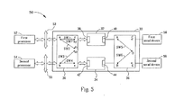
50 can also exchange data with each other. Please refer to Fig.7 showing a fourth state
of the computer system 50 according to the second embodiment of the present
invention. In the computer system 50 shown in Fig.7, the switches SW1, SW2, SW3,
SW4, SW5, SW6, SW7 in the control unit 36 connect respectively node a and d2, node
a and d2, node b and d2, node b and d2, node A and C, node B and E, node c and e. In
this setup, the first serial device 56 can exchange data with the second serial device 58
via the first UART 32 and the second UART 34. When the first serial device (host) 56
transmits frame data to the second serial device 58, the RECV bit (bit 1) in the
STATUS register of the six registers within the first UART 32 will be determined as
"1" in order to receive the frame data from the first serial device 56, and the lowest bit
(XMIT bit) in the STATUS register of the six registers within the second UART 34
will be determined as "1" in order to send out the frame data (transformed from 8-bit
data which is transformed from the frame data by the first UART 32) to the second
serial device 58. The same procedure applies in the case that the second serial device
58 transmits frame data to the first serial device 56.
In the computer system 50 shown in Fig.5, the first processor 52 and the second
processor 54 is assumed to have the same operational voltage. However, in some
computer systems having two processors, the operational voltage of the two
processors may not be the same, meaning that data cannot be exchanged between two
processors. Please refer to Fig.8 showing a status of a computer system 80 according
to the third embodiment of the present invention. A third processor 82 and a fourth
processor 84 in the computer system 80 have different operational voltages (e.g. the
operational voltage of the third processor 82 is 2.5v, and the operational voltage of the
fourth processor 84 is 3.3v). The computer system 80 also includes a first serial
device 56, a second serial device 58, a first system bus 53, a second system bus 55,
and a UART ASIC 90. Being different from the UART ASIC 30 shown in Fig.2, the
UART ASIC 90 includes not only the first UART 32, the second UART 34, and a
control unit 96 (the control unit 96 is different from the control unit 36 in that node e
of the control unit 36 is replaced by node e1 and e2 in the control unit 96), but also a
level shifter 98 electrically connected to node e1. When switches SW1, SW2, SW3,
SW4, SW5, SW6, SW7 in the control unit 96 connect respectively node a and c, node a
and d1, node b and d2, node b and e1, node A and D, node B and D, node c and f; the
level shifter 98 converts the frame data output by the third processor 82 into a
predetermined voltage. Then the first UART 32 transmits the converted frame data to
the second UART 34 and the control unit 96. Afterwards, the level shifter 98 converts
it into voltage level of the fourth processor 84. The same procedure applies when the
frame data is output by the fourth processor 84 instead of the third processor 82. In
such a manner, even if the operational voltages are different, the third processor 82
and the fourth processor 84 in the computer system 80 can exchange data.
In the UART ASIC 90 shown in Fig.8, the level shifter 98 is located outside of
the first UART 32 and the second UART 34. Of course though, the level shifters in
the serial/parallel data transformer module according to the present invention can be
respectively installed in the first UART 32 and/or the second UART 34.
In contrast to the prior art, the serial/parallel data transformer module according
to the present invention can allow the following: a single processor to exchange data
with two serial devices simultaneously, each processor to exchange data with a
different serial device simultaneously, two processors to exchange data with each
other, and two serial devices to exchange data with each other. Moreover, even two
processors having different operational voltages can exchange data with each other by
converting the level of the frame data transmitted or received by the two processors
by means of the level shifter.
Claims (29)
- A computer system (50, 80) comprising:characterized by:a first processor (52, 82);a first serial/parallel data transformer (32) comprising a parallel port (38) and a serial port (40);a second serial/parallel data transformer (34) comprising a parallel port (42) and a serial port (44); anda control unit (36, 96) for selectively connecting in an electrical fashion the first processor (52, 82) to the parallel port (38) of the first serial/parallel data transformer (32), the first processor (52, 82) to both the parallel port (38) of the first serial/parallel data transformer (32) and the parallel port (42) of the second serial/parallel data transformer (34), or the first processor (52, 82) to the serial port (40) of the first serial/parallel data transformer (32); and electrically connecting the serial port (40) of the first serial/parallel data transformer (32) to the serial port (44) of the second serial/parallel data transformer (34).
- The computer system (50, 80) of claim 1 characterized in that the computer system (50, 80) further comprises a serial device (56) electrically connected to the serial port (40) of the first serial/parallel data transformer (32).
- The computer system (50, 80) of claim 1 characterized in that the computer system (50, 80) further comprises two serial devices (56, 58) respectively electrically connected to the serial port (40) of the first serial/parallel data transformer (32) and the serial port (44) of the second serial/parallel data transformer (34).
- The computer system (50, 80) of claim 1 characterized in that the computer system (50, 80) further comprises a second processor (54, 84) electrically connected to the parallel port (42) of the second serial/parallel data transformer (34).
- The computer system (50) of claim 4 characterized in that the first processor (52) has an operational voltage equal to that of the second processor (54).
- The computer system (80) of claim 4 characterized in that the first processor (82) has an operational voltage different from that of the second processor (84).
- The computer system (80) of claim 1 characterized in that the computer system (80) further comprises a level shifter (98) electrically connected between the serial port (40) of the first serial/parallel data transformer (32) and the serial port (44) of the second serial/parallel data transformer (34) for adjusting the level of data transmitted between the serial port (40) of the first serial/parallel data transformer (32) and the serial port (44) of the second serial/parallel data transformer (34).
- The computer system (50, 80) of claim 1 characterized in that the control unit (36, 96) is a logic circuit.
- The computer system (50, 80) of claim 1 characterized in that the control unit (36, 96) is a program code stored in a memory.
- The computer system (50, 80) of claim 1 characterized in that the first serial/parallel data transformer (32), the second serial/parallel data transformer (34), and the control unit (36, 96) are integrated on an application specific integrated circuit (ASIC).
- The computer system (50, 80) of claim 1 characterized in that the first serial/parallel data transformer (32) is a universal asynchronous receiver/transmitter (UART).
- The computer system (50, 80) of claim 1 characterized in that the first serial/parallel data transformer (32) is an inter-IC (I2C).
- The computer system (50, 80) of claim 1 characterized in that the first serial/parallel data transformer (32) is a universal serial bus (USB).
- The computer system (50, 80) of claim 1 characterized in that the first serial/parallel data transformer (32) is a Serial Peripheral Interface (SPI).
- The computer system (50, 80) of claim 1 characterized in that the first serial/parallel data transformer (32) is a Synchronous Serial Protocol interface (SSP).
- The computer system (50, 80) of claim 1 characterized in that the first serial/parallel data transformer (32) is a Microwire interface.
- The computer system (50, 80) of claim 1 characterized in that the first serial/parallel data transformer (32) is an Inter IC Sound interface (I2S).
- A serial/parallel data transformer module (30, 90) comprising:characterized by:a first serial/parallel data transformer (32) comprising a parallel port (38) and a serial port (40);a second serial/parallel data transformer (34) comprising a parallel port (42) and a serial port (44); anda control unit (36, 96) for selectively connecting in an electrical fashion the parallel port (38) of the first serial/parallel data transformer (32) to the parallel port (42) of the second serial/parallel data transformer (34) or the serial port (40) of the first serial/parallel data transformer (32) to the serial port (44) of the second serial/parallel data transformer (34).
- The serial/parallel data transformer module (90) of claim 18 characterized in that the serial/parallel data transformer module (90) further comprises a level shifter (98) electrically connected between the serial port (40) of the first serial/parallel data transformer (32) and the serial port (44) of the second serial/parallel data transformer (34) for adjusting the level of data transmitted between the serial port (40) of the first serial/parallel data transformer (32) and the serial port (44) of the second serial/parallel data transformer (34).
- The serial/parallel data transformer module (30, 90) of claim 18 characterized in that the control unit (36, 96) is a logic circuit.
- The serial/parallel data transformer module (30, 90) of claim 18 characterized in that the control unit (36, 96) is a program code stored in a memory.
- The serial/parallel data transformer module (30, 90) of claim 18 characterized in that the first serial/parallel data transformer (32), the second serial/parallel data transformer (34), and the control unit (36, 96) are integrated on an ASIC.
- The serial/parallel data transformer module (30, 90) of claim 18 characterized in that the first serial/parallel data transformer (32) is a UART.
- The serial/parallel data transformer module (30, 90) of claim 18 characterized in that the first serial/parallel data transformer (32) is an I2C.
- The serial/parallel data transformer module (30, 90) of claim 18 characterized in that the first serial/parallel data transformer (32) is a USB.
- The serial/parallel data transformer module (30, 90) of claim 18 characterized in that the first serial/parallel data transformer (32) is a SPI.
- The serial/parallel data transformer module (30, 90) of claim 18 characterized in that the first serial/parallel data transformer (32) is a SSP.
- The serial/parallel data transformer module (30, 90) of claim 18 characterized in that the first serial/parallel data transformer (32) is a Microwire.
- The serial/parallel data transformer module (30, 90) of claim 18 characterized in that the first serial/parallel data transformer (32) is an I2S.
Priority Applications (1)
| Application Number | Priority Date | Filing Date | Title |
|---|---|---|---|
| EP04006549A EP1577786A1 (en) | 2004-03-18 | 2004-03-18 | Serial/parallel data transformer module and related computer system |
Applications Claiming Priority (1)
| Application Number | Priority Date | Filing Date | Title |
|---|---|---|---|
| EP04006549A EP1577786A1 (en) | 2004-03-18 | 2004-03-18 | Serial/parallel data transformer module and related computer system |
Publications (1)
| Publication Number | Publication Date |
|---|---|
| EP1577786A1 true EP1577786A1 (en) | 2005-09-21 |
Family
ID=34833642
Family Applications (1)
| Application Number | Title | Priority Date | Filing Date |
|---|---|---|---|
| EP04006549A Withdrawn EP1577786A1 (en) | 2004-03-18 | 2004-03-18 | Serial/parallel data transformer module and related computer system |
Country Status (1)
| Country | Link |
|---|---|
| EP (1) | EP1577786A1 (en) |
Cited By (2)
| Publication number | Priority date | Publication date | Assignee | Title |
|---|---|---|---|---|
| CN101454763B (en) * | 2006-05-24 | 2011-05-25 | 罗伯特.博世有限公司 | Gateway for transferring data between serial buses |
| WO2013095538A1 (en) * | 2011-12-22 | 2013-06-27 | Intel Corporation | Interconnection of multiple chips in a package utilizing on-package input/output interfaces |
Citations (2)
| Publication number | Priority date | Publication date | Assignee | Title |
|---|---|---|---|---|
| WO1989009967A1 (en) * | 1988-04-08 | 1989-10-19 | Cogent Research, Inc. | Computing machine with hybrid communication architecture |
| US5717871A (en) * | 1995-08-17 | 1998-02-10 | I-Cube, Inc. | Crossbar switch with input/output buffers having multiplexed control inputs |
-
2004
- 2004-03-18 EP EP04006549A patent/EP1577786A1/en not_active Withdrawn
Patent Citations (2)
| Publication number | Priority date | Publication date | Assignee | Title |
|---|---|---|---|---|
| WO1989009967A1 (en) * | 1988-04-08 | 1989-10-19 | Cogent Research, Inc. | Computing machine with hybrid communication architecture |
| US5717871A (en) * | 1995-08-17 | 1998-02-10 | I-Cube, Inc. | Crossbar switch with input/output buffers having multiplexed control inputs |
Cited By (3)
| Publication number | Priority date | Publication date | Assignee | Title |
|---|---|---|---|---|
| CN101454763B (en) * | 2006-05-24 | 2011-05-25 | 罗伯特.博世有限公司 | Gateway for transferring data between serial buses |
| WO2013095538A1 (en) * | 2011-12-22 | 2013-06-27 | Intel Corporation | Interconnection of multiple chips in a package utilizing on-package input/output interfaces |
| US9535865B2 (en) | 2011-12-22 | 2017-01-03 | Intel Corporation | Interconnection of multiple chips in a package |
Similar Documents
| Publication | Publication Date | Title |
|---|---|---|
| US20050138246A1 (en) | Serial/parallel data transformer module and related computer system | |
| CA2528392C (en) | Multi-functional port | |
| US7424566B2 (en) | Method, system, and apparatus for dynamic buffer space allocation | |
| EP1384154B1 (en) | Communication interface for an electronic device | |
| US7752342B2 (en) | Interface integrated circuit device for a USB connection | |
| EP2146286B1 (en) | Converter and control system | |
| US7401168B2 (en) | Method and apparatus for communication via serial multi-port, and recording medium | |
| US7756123B1 (en) | Apparatus, system, and method for swizzling of a PCIe link | |
| US7813362B2 (en) | Communication apparatus, electronic apparatus, imaging apparatus | |
| WO2006115753A2 (en) | Virtualized pci switch | |
| US8683085B1 (en) | USB interface configurable for host or device mode | |
| US7424567B2 (en) | Method, system, and apparatus for a dynamic retry buffer that holds a packet for transmission | |
| US7424565B2 (en) | Method and apparatus for providing efficient output buffering and bus speed matching | |
| CN111694781A (en) | ARM main control board based on data acquisition system | |
| US5905744A (en) | Test mode for multifunction PCI device | |
| JP4928715B2 (en) | Serial data transfer device, image output device, image input device, and image forming device | |
| EP1577786A1 (en) | Serial/parallel data transformer module and related computer system | |
| US8295368B1 (en) | Method and apparatus for improved interfacing of connections between a multiplicity of handheld devices | |
| CN1321382C (en) | Serial/parallel data conversion module and related computer system | |
| KR102662356B1 (en) | Protocol converting apparatus | |
| KR200377353Y1 (en) | Data communication device having switching function | |
| KR950012501B1 (en) | High-speed data input / output method in personal computer (PC) | |
| MSB | Legacy Digital I/O Interfacing Standards | |
| KR20050056213A (en) | Interface integrated circuit device for a usb connection | |
| KR20020080522A (en) | Status of interface for transmitter-receiver data |
Legal Events
| Date | Code | Title | Description |
|---|---|---|---|
| PUAI | Public reference made under article 153(3) epc to a published international application that has entered the european phase |
Free format text: ORIGINAL CODE: 0009012 |
|
| 17P | Request for examination filed |
Effective date: 20040318 |
|
| AK | Designated contracting states |
Kind code of ref document: A1 Designated state(s): AT BE BG CH CY CZ DE DK EE ES FI FR GB GR HU IE IT LI LU MC NL PL PT RO SE SI SK TR |
|
| AX | Request for extension of the european patent |
Extension state: AL LT LV MK |
|
| STAA | Information on the status of an ep patent application or granted ep patent |
Free format text: STATUS: THE APPLICATION HAS BEEN WITHDRAWN |
|
| 18W | Application withdrawn |
Effective date: 20060105 |