EP1577640B1 - Method and device for hydrostatic levelling - Google Patents
Method and device for hydrostatic levelling Download PDFInfo
- Publication number
- EP1577640B1 EP1577640B1 EP04450238A EP04450238A EP1577640B1 EP 1577640 B1 EP1577640 B1 EP 1577640B1 EP 04450238 A EP04450238 A EP 04450238A EP 04450238 A EP04450238 A EP 04450238A EP 1577640 B1 EP1577640 B1 EP 1577640B1
- Authority
- EP
- European Patent Office
- Prior art keywords
- measurement
- hose
- pressure
- measuring
- liquid column
- Prior art date
- Legal status (The legal status is an assumption and is not a legal conclusion. Google has not performed a legal analysis and makes no representation as to the accuracy of the status listed.)
- Not-in-force
Links
Images
Classifications
-
- E—FIXED CONSTRUCTIONS
- E03—WATER SUPPLY; SEWERAGE
- E03F—SEWERS; CESSPOOLS
- E03F7/00—Other installations or implements for operating sewer systems, e.g. for preventing or indicating stoppage; Emptying cesspools
- E03F7/12—Installations enabling inspection personnel to drive along sewer canals
-
- G—PHYSICS
- G01—MEASURING; TESTING
- G01C—MEASURING DISTANCES, LEVELS OR BEARINGS; SURVEYING; NAVIGATION; GYROSCOPIC INSTRUMENTS; PHOTOGRAMMETRY OR VIDEOGRAMMETRY
- G01C5/00—Measuring height; Measuring distances transverse to line of sight; Levelling between separated points; Surveyors' levels
- G01C5/04—Hydrostatic levelling, i.e. by flexibly interconnected liquid containers at separated points
Definitions
- the invention relates to a method for determining the longitudinal profile of elongated structures, especially buried in the ground structures, such as pipes and the like, in which one detects the vertical distance of the building from a reference point at several, distributed over the length of the building measuring points by at each measuring point the hydrostatic pressure of a liquid column between the respective measuring point and the reference point is detected and calculated from the detected value for the hydrostatic pressure, the height distance of the respective measuring point from the reference point.
- the invention further relates to a device with which the method according to the invention can be carried out.
- underground pipelines in which a non-pressurized medium is transported (sewer pipes, drainage pipes) have a uniform slope, so that a proper transport of the medium is ensured by gravity.
- the slope of a pipeline can be easily assessed at the open trench.
- measuring instruments have been used to test the gradient of pipelines, which determine the average pipe inclination with the aid of laser beams.
- a device for checking the position of laid underground pipes is known.
- a measuring head is provided for testing the position of a tube, which is connected to a flexible hose, wherein the hose is connected to a pulling device.
- the hose line reaches into a measuring trolley, in which measuring and recording devices are housed.
- the measuring head is in the device according to the DE 28 10 687 A essentially sleeve-shaped and contains a piezoresistive pressure transducer whose pressure chamber is connected via a connecting hose line with a reservoir with a relatively large cross-section and large volume.
- the measuring head is first inserted into the pipe to be measured and then as evenly pulled out of the tube again.
- the initial value of the hydrostatic pressure acting on the pressure transducer via the connecting hose line is measured and changes in the pressure as a function of the height of the measuring head are detected during the extraction of the measuring head from the drainage pipe. Any corrections of the measurement result, taking into account the air pressure or the temperature are in the DE 28 10 687 A not mentioned.
- the WO 96/18867 A describes a device for measuring height differences, the device described therein in one-man operation under confusing, local conditions and under varying temperature and pressure conditions constantly sufficiently precise To deliver measurement results.
- a device whose measuring system is completely closed, whereby influences the ambient air pressure by a flexible membrane in the reference memory, which is part of the known device in the manner of a modified tube scale together with other components, to be compensated.
- the known device has a liquid-filled connecting hose and a measuring head.
- the reference memory is placed on a footprint (eg a floor of a building) and the measuring head, which is connected to the reference memory by a flexible conduit (connecting hose), above the footprint on which the reference memory is mounted, brought to the place that should have a predetermined height distance from the footprint.
- the measuring head In the case of the known device, the measuring head must be mounted and read by the operator at the measuring point. Therefore, the from the WO 96/18867 known device because of the membrane used in the reference container and the closed version for measurements of larger differences in height only partially suitable. This is also because in the known device must be paid to a low-pressure and low-tension, as well as a horizontal training of the reference mirror.
- the from the WO 96/18867 Known device exclusively suitable to measure from a predetermined fixed point in the height, but not to determine the course and the position of a pipe.
- the document US-A-5 517 869 describes a hydrostatic altitude measurement with superatmospheric pressure in a closed equalizing vessel at the upper end of a measuring tube containing the measuring liquid.
- the separately detected temperature of the liquid is taken into account in the calculation of the height distance.
- the object of the invention is to provide a method by which the position of (elongated) structures (for example, underground laid pipelines) can be measured with higher accuracy and faster and optionally recorded, as with the from AT 409 671 B known methods.
- This object is achieved by a method which is characterized in that the hydrostatic pressure of a liquid column loaded at its upper end with superatmospheric pressure with the upper end of the liquid column forming the reference point and, in the calculation of the height distance from the measured values of the hydrostatic pressure, taking into account the pressure separately measured at the time of measurement, which loads the upper end of the liquid column.
- the invention also provides an apparatus for carrying out the method.
- This device comprises a filled with a measuring liquid measuring tube having at the lower end a pressure sensor which is installed in a provided at the lower end of the measuring tube probe, and at least one built in the probe temperature sensor, wherein the upper end of the tube with a surge tank for the measuring liquid, according to the invention is characterized in that in the region of the closed expansion tank, a sensor for detecting the pressure in the expansion tank is provided.
- the basic idea of the method according to the invention is based on the evaluation of the hydrostatic pressure in a liquid column, when the lower end of this column in the rising or falling course of a building, e.g. a pipeline, is moved.
- a building e.g. a pipeline
- the height difference between the respective measuring point and a reference point can be determined and so laid the course and subsequently the slope of buildings, especially from underground Built-in, such as sewer pipes, pipes, etc., are determined.
- temperature-compensated pressure sensors are used.
- the upper end of the hose is connected to a surge tank for the measuring liquid, and its history (in particular horizontal course) to know exactly this can be carried out with the method according to the invention and the device according to the invention.
- landslides can also be observed and controlled before they become visible on the surface.
- house connections can also be measured with pinpoint accuracy, especially in the urban area and in grabless procedures.
- the method of the invention opens up the possibility of accurately measuring subsurface terrain.
- the inventive method for determining longitudinal profiles works basically with the utilization of the pressure of a liquid column on a to be measured structure (sewer pipe, etc.) arranged and moved along the building pressure sensor (probe).
- the pressure prevailing in the expansion tank is also taken into consideration.
- the temperature in the pressure sensor, the temperature of the liquid and / or the ambient air temperature can be detected and taken into account in determining the measurement results.
- a particularly accurate and reproducible measurement result can be achieved, even if the temperature at the measuring probe (which is arranged, for example, in the channel), the temperature in the tube, which is not yet in the channel, and the temperature of the ambient air are measured.
- the respective density of the liquid in the hose line, at the end of which the pressure sensor is located is taken into account when the hydrostatic pressure is evaluated to determine the ride height between the measuring point and the reference point.
- one works with a combination of several measurements, such as pressure above the upper end of the liquid column (eg in the surge tank), temperature (the liquid in the liquid column) and hydrostatic pressure to a precise Measurement result, for example, has an accuracy of 1 mm / measurement or less to achieve.
- the device according to the invention which in principle is an (electronic) Absolute pressure gauge is, height differences can be detected using the hydrostatic pressure of a liquid column.
- the weight that possesses the liquid parts due to the instantaneous height difference ie the height difference between measuring point and reference point at the time of measurement, be detected by means of a pressure sensor and utilized to determine the height distance.
- the reference point of this liquid column is at its upper end, wherein it is preferred that at the upper end of the tube in which the liquid column is contained, a surge tank is provided.
- a surge tank changes in the upper level of the liquid column remain small, even if the cross section and / or the length of the tube in which the liquid column is contained changes as the probe progresses from measurement point to measurement point.
- a pressure sensor for detecting the pressure above the upper end of the liquid column is provided in the device according to the invention. This the pressure above the liquid column detecting sensor is arranged for example in the expansion tank.
- the sewer Prior to the determination of the longitudinal profile of the sewer pipe, the sewer is cleaned, for example by means of a high-pressure septic tank, to ensure that the probe used in the method according to the invention lies on the bottom of the pipe and not on deposits there.
- the channel TV system can be removed from the channel, whereby it is possible to simultaneously insert into the channel a pull-in cord for moving the probe according to the invention to introduce to the first measuring point.
- a vehicle on which the device can be installed to carry out the process placed in front of a manhole in position and the hose a piece of the hose cassette (hose supply, for example 250 lfm) withdrawn and adjusted with a calibrated Justierrohr.
- hose cassette hose supply, for example 250 lfm
- a reservoir whose bleed screw and valve is closed.
- This process adjusts the self-checking measuring system.
- the pull-in cord previously introduced
- the measuring probe is drawn into the sewer pipe with the measuring hose, whereby the hose can be guided via deflection rollers in the shaft and on the measuring vehicle. Extraction or retraction of the measuring hose can be supported by a motor-assisted drive.
- the introduced measuring probe is positioned at the first measuring point and the measured value is taken and stored as the initial value for all further measurements after the stabilization of the measuring liquid. Then you can start with the other measuring procedures. To this end, if necessary supported by a motor-assisted hose return, the measuring hose is pulled in a bit and positioned in the next measuring point.
- an automatic length measuring device for the measuring tube can be provided on the tube cassette, so that, for example, measurements can be carried out at intervals of one meter.
- This settling time can be about 15 to 45 seconds, depending on the length of the measuring line and the difference in height between the measuring probe and the expansion tank.
- the measurements are repeated until the probe has reached the end of the track to be tested.
- the correction of the measured values for the hydrostatic pressure by including the pressure above the upper end of the liquid column of the ambient temperature, the temperature in the range in the range of the probe and the temperature liquid in the area of the hose stock can be performed using a computer program, so that with each measurement without additional measures correct values for the vertical distance of the measuring point be obtained from the reference point from the measured by the probe hydrostatic pressure of the liquid column.
- hose packages are provided as a supply for the measuring hose on the device according to the invention, it is possible to use hose packages with different lengths. For example, hose packages with lengths of 250 m or hose packages with a length of 60 m can be used.
- the length of the hose package is also taken into account. This is done, for example, so that the length of the measuring section and the shaft depth are taken into account. This takes into account the following. For example, in January at an outside temperature of -15 ° C, a measurement is made in seepage pipelines in a landfill, which itself has a temperature of + 80 ° C. This results in a temperature difference of 95 ° C.
- the hose package has a length of 250 m, the test section is 50 m, the shaft depth is 5 m. This means that of the 250 m of the hose package 55 m, a temperature of + 80 ° C and 195 m have a temperature of -15 ° C. This means that the density of the liquid in the measuring tube is different. These temperature-related density differences can also be taken into account by the computer program when evaluating the hydrostatic pressure detected by the pressure sensor in the measuring probe.
- the drawing shows a device for determining the longitudinal profile of a sewer pipe between two manholes.
- a system for documenting the location and time of the measurement performed can also be combined. This can be done, for example, by combining a GPS device and a real-time clock with the computer program.
- a high accuracy of the measurements of pressure and temperature can be achieved if a pressure sensor with integrated temperature sensor is used in the measuring probe.
- the acquired measured values are forwarded to the computer via a serial data line which also supplies the (combined) pressure-temperature sensor with energy.
- the temperature of the sensor, the sensor type and the sensor number can also be transmitted via the data line. It is thus possible to automatically detect the connected sensor by the computer.
- the pressure acting on the liquid column arranged with its upper end in the expansion tank is detected by the pressure sensor associated with the expansion tank 7 and taken into account mathematically in the computer when the hydrostatic pressure detected by the pressure sensor is evaluated to determine the vertical distance between the measuring point and the reference point ,
- the density of the liquid used in the measuring tube at the time of measurement and the data received from the measuring probe and the air pressure gauge are stored in a RAM in the computer by the time and date of the built-in real-time clock and the coordinates of the integrated GPS system. Via an interface, these data can be read out and evaluated via a PC.
- each measurement is marked for later evaluation with an individual identifier for project and location. This is possible, for example, with the help of the integrated GPS system and the integrated real-time clock.
- the gradient of drainage systems in landfills can be measured exactly and thus its functional status can be checked. Poorly functioning drainage systems can lead to considerable underground contamination.
- the stability of the ground and its close observation allow a higher landfill of the landfill, if there is no lowering of the terrain and endangerment of the drainage. Higher landfill saves valuable landfill space and, in the limit, the installation of a new landfill.
- the simultaneous measurement of the temperature allows conclusions about the gasification and other reactions within the garbage body.
- the settlement of earth dams, structures of roads and railroads can be detected early, as these settlements can be detected in the subsurface before visible effects on the surface occur. Early detection of security risks can help prevent or prevent damage.
- Landslides can be detected early by taking control measurements, as ground motion becomes apparent in the ground before the first signs become visible on the surface.
- the hydrostatic pressure of a column of liquid is measured between measuring points distributed over the length of the structure and a reference point, and from the values recorded, the height distance of the respective measuring point calculated from the reference point.
- a liquid-filled tube 3 which has a pressure sensor for detecting the hydrostatic pressure at the lower end, and which is connected at its upper end to a measuring liquid equalizing vessel 7 closed during the measurement.
- the compensating vessel 7 is associated with a pressure sensor 9 for detecting the pressure.
- the pressure prevailing in the expansion tank 7 and the prevailing temperature, which is detected separately, and influences the density of the measuring liquid, are taken into account when evaluating the detected values for the hydrostatic pressure.
- the position of the measuring system and the time of the measuring process are recorded and registered via GPS.
Abstract
Description
Die Erfindung betrifft ein Verfahren zum Bestimmen des Längsprofils von langgestreckten Bauwerken, insbesondere im Erdreich verlegten Bauwerken, wie Rohren u.dgl., bei dem man den Höhenabstand des Bauwerkes von einem Referenzpunkt an mehreren, über die Länge des Bauwerkes verteilten Messpunkten erfasst, indem man an jedem Messpunkt den hydrostatischen Druck einer Flüssigkeitssäule zwischen dem jeweiligen Messpunkt und dem Referenzpunkt erfasst und aus dem erfassten Wert für den hydrostatischen Druck den Höhenabstand des jeweiligen Messpunktes vom Referenzpunkt errechnet.The invention relates to a method for determining the longitudinal profile of elongated structures, especially buried in the ground structures, such as pipes and the like, in which one detects the vertical distance of the building from a reference point at several, distributed over the length of the building measuring points by at each measuring point the hydrostatic pressure of a liquid column between the respective measuring point and the reference point is detected and calculated from the detected value for the hydrostatic pressure, the height distance of the respective measuring point from the reference point.
Die Erfindung betrifft weiters eine Vorrichtung, mit der das erfindungsgemäße Verfahren ausgeführt werden kann.The invention further relates to a device with which the method according to the invention can be carried out.
Beispielsweise sollen unterirdisch verlegte Rohrleitungen, in denen ein nicht unter Druck stehendes Medium transportiert wird (Kanalrohre, Drainagerohre) ein gleichmäßiges Gefälle aufweisen, damit ein einwandfreier Transport des Mediums auf Grund der Schwerkraft gewährleistet ist. Je schwieriger die Gefällebedingungen eines derartigen Rohrsystems sind (z.B. flaches Gelände), desto wichtiger ist nicht nur das Durchschnittsgefälle, sondern auch das Erfordernis, dass das Gefälle über den Verlauf der ganzen Rohrleitung einheitlich und konstant ist, also keine Ausbauchungen in vertikaler Richtung auftreten.For example, underground pipelines, in which a non-pressurized medium is transported (sewer pipes, drainage pipes) have a uniform slope, so that a proper transport of the medium is ensured by gravity. The more difficult the gradient conditions of such a pipe system are (e.g., flat terrain), the more important is not only the average gradient, but also the requirement that the slope be uniform and constant over the course of the entire pipeline, ie, no bulges in the vertical direction.
Das Gefälle einer Rohrleitung kann am offenen Rohrgraben ohne Weiteres beurteilt werden.The slope of a pipeline can be easily assessed at the open trench.
Nach dem der Rohrgraben verschüttet worden ist, können insbesondere bei nicht einwandfreier Rohrbettung, bei schwierigen Untergrundverhältnissen, im setzungsgefährdeten Gelände und/oder durch zeitbedingte oder unvorhersehbare Belastungen von der Oberfläche her erhebliche Abweichungen des Gefälles der Rohrleitung vom Idealgefälle auftreten, welche die Funktion und Haltbarkeit des verlegten Rohrstranges negativ beeinflussen.After the pipe trench has been spilled, considerable deviations of the slope of the pipe from the ideal gradient may occur especially in improper pipe bedding, under difficult ground conditions, in settlement risky terrain and / or by time-related or unpredictable loads from the surface forth, the function and durability of the installed pipe string negatively influence.
Es ist daher erforderlich, das Gefälle von Rohrleitungen von Zeit zu Zeit zu überprüfen, was insbesondere bei Abwasserhauptsträngen, Kanalhausanschlüssen, Abwassersystemen bei Tankstellen und Fabriken, in die Öl- oder Fettabscheider eingebaut sind, bei Drainagesystemen von Mülldeponien wesentlich und auch bei der Kollaudierung von neu verlegten Abwasserkanälen wichtig ist. Auch bei in Deponien verlegten Leitungen, die für das Sammeln und das Ableiten von Deponiegasen bestimmt sind, ist ein bestimmtes Gefälle wesentlich.It is therefore necessary to check the slope of pipelines from time to time, especially drainage systems in sewer main sewers, sewer connections, gas station sewer systems and factories incorporating oil or grease separators Of landfills essential and also in the Kollaudierung newly laid sewers is important. Even in laid in landfills lines, which are intended for the collection and discharge of landfill gas, a certain gap is essential.
Für die Prüfung des Gefälles von Rohrleitungen wurden bislang Messgeräte verwendet, welche die durchschnittliche Rohrneigung mit Hilfe von Laserstrahlen ermitteln.So far, measuring instruments have been used to test the gradient of pipelines, which determine the average pipe inclination with the aid of laser beams.
Auch Neigungsmesser in Kombination mit Kanal-TV-Kameras sind ungenau und lassen keine exakten Vergleichsmessungen in längeren Zeitabständen zu.Also inclinometer in combination with channel TV cameras are inaccurate and do not allow exact comparison measurements at longer intervals.
Aus der
Die
Das Dokument
Ein Verfahren der eingangs genannten Gattung und eine zum Ausführen desselben geeignete Vorrichtung ist aus der
Aufgabe der Erfindung ist es, ein Verfahren anzugeben, mit dem die Lage von (langgestreckten) Bauwerken (beispielsweise von unterirdisch verlegte Rohrleitungen) mit höherer Genauigkeit und rascher vermessen und gegebenenfalls aufgezeichnet werden kann, als mit dem aus der
Gelöst wird diese Aufgabe mit einem Verfahren, das dadurch gekennzeichnet ist, dass man den hydrostatischen Druck einer an ihrem oberen Ende mit Über-Atmosphären-Druck belasteten Flüssigkeitssäule misst, wobei das obere Ende der Flüssigkeitssäule den Referenzpunkt bildet, und dass man bei der Berechnung des Höhenabstandes aus den gemessenen Werten des hydrostatischen Drucks den im Zeitpunkt der Messung gesondert erfassten Druck, der das obere Ende des Flüssigkeitssäule belastet, berücksichtigt.This object is achieved by a method which is characterized in that the hydrostatic pressure of a liquid column loaded at its upper end with superatmospheric pressure with the upper end of the liquid column forming the reference point and, in the calculation of the height distance from the measured values of the hydrostatic pressure, taking into account the pressure separately measured at the time of measurement, which loads the upper end of the liquid column.
Die Erfindung stellt auch eine Vorrichtung zum Durchführen des Verfahrens zur Verfügung. Diese Vorrichtung mit einem mit einer Messflüssigkeit gefüllten Messschlauch, der am unteren Ende einen Drucksensor, der in einer am unteren Ende des Messschlauches vorgesehenen Messsonde eingebaut ist, sowie wenigstens einen in der Messsonde ein gebauten Temperatursensor aufweist, wobei das obere Ende des Schlauches mit einem Ausgleichsgefäß für die Messflüssigkeit verbunden ist, ist erfindungsgemäß dadurch gekennzeichnet, dass im Bereich des geschlossenen Ausgleichsgefäßes ein Sensor zum Erfassen des Druckes im Ausgleichsgefäß vorgesehen ist.The invention also provides an apparatus for carrying out the method. This device comprises a filled with a measuring liquid measuring tube having at the lower end a pressure sensor which is installed in a provided at the lower end of the measuring tube probe, and at least one built in the probe temperature sensor, wherein the upper end of the tube with a surge tank for the measuring liquid, according to the invention is characterized in that in the region of the closed expansion tank, a sensor for detecting the pressure in the expansion tank is provided.
Bevorzugte und vorteilhafte Ausgestaltungen des erfindungsgemäßen Verfahrens und der erfindungsgemäßen Vorrichtung sind Gegenstand der abhängigen Unteransprüche.Preferred and advantageous embodiments of the method and the device according to the invention are the subject of the dependent subclaims.
Der grundsätzliche Gedanke des erfindungsgemäßen Verfahrens beruht auf der Auswertung des hydrostatischen Druckes in einer Flüssigkeitssäule, wenn das untere Ende dieser Säule im ansteigenden oder fallenden Verlauf eines Bauwerkes, z.B. einer Rohrleitung, verschoben wird. Auf Grund der in über die Länge des Bauwerkes, vorzugsweise gleichmäßig, verteilten Messpunkten gemessenen Werte für den hydrostatischen Druck, kann der Höhenabstand zwischen dem jeweiligen Messpunkt und einem Bezugspunkt ermittelt und so der Verlauf und in weiterer Folge das Gefälle von Bauwerken, insbesondere von unterirdisch verlegten Einbauten, wie Kanalrohren, Leitungen usw., ermittelt werden.The basic idea of the method according to the invention is based on the evaluation of the hydrostatic pressure in a liquid column, when the lower end of this column in the rising or falling course of a building, e.g. a pipeline, is moved. On the basis of measured over the length of the building, preferably uniformly distributed measuring points for the hydrostatic pressure, the height difference between the respective measuring point and a reference point can be determined and so laid the course and subsequently the slope of buildings, especially from underground Built-in, such as sewer pipes, pipes, etc., are determined.
Da bei dem erfindungsgemäßen Verfahren und der erfindungsgemäßen Vorrichtung - anders als bei der
Bevorzugt werden temperaturkompensierte Drucksensoren eingesetzt.Preferably, temperature-compensated pressure sensors are used.
Anwendungsmöglichkeiten des erfindungsgemäßen Verfahren und der erfindungsgemäßen Vorrichtung sind beispielsweise die folgenden:Possible applications of the method according to the invention and the device according to the invention are, for example, the following:
Erfassen des Verlaufes von neu und alt verlegten Abwasserkanälen. Das ermöglicht eine genaue Überprüfung der ordnungsgemäßen Verlegung von Kanalrohren und die Beurteilung der Funktionsfähigkeit von Abwassersystemen.Capture the history of newly installed and old sewers. This allows for a precise check of the proper installation of sewer pipes and the assessment of the functionality of sewage systems.
Erfassen und laufendes Kontrollieren von Drainagesystemen bei Mülldeponien. Die Aufschüttung von Müll kann durch die Druckbelastung das Drainagesysteme in seiner Funktionsfähigkeit beeinflussen, indem es zu Setzungen in den Drainage-Rohrleitungen (Leitungen für Flüssigkeiten und/oder Deponiegase) kommt. Eine ständige Kontrolle ist demnach erforderlich und ermöglicht eine höhere Schüttung, wenn die Stabilität des Untergrundes nachgewiesen werden kann.Capture and continuously control drainage systems at landfills. The accumulation of garbage can influence the drainage system in its functionality by the pressure load, by settling in the drainage piping (lines for liquids and / or landfill gas) comes. A constant control is therefore required and allows a higher bed if the stability of the substrate can be demonstrated.
Mit Hilfe des erfindungsgemäßen Verfahrens kann das Setzungsverhalten von Bahn- und Straßentrassen und sonstigen Aufschüttungen, die insbesondere bei problematischen Untergrundverhältnissen einen Risikofaktor darstellen, ständig überprüft werden.With the help of the method according to the invention, the settlement behavior of railway and road lines and other landfills, which represent a risk factor especially in problematic ground conditions, can be constantly checked.
Überall dort, wo es notwendig ist, einen Rohrvortrieb millimetergenau zu positionieren (Hausanschlüsse, Kabelunterführungen, Düker usw.), wobei das obere Ende des Schlauches mit einem Ausgleichsgefäß für die Messflüssigkeit verbunden ist, und dessen Verlauf (insbesondere Horizontalverlauf) genau zu kennen, kann dies mit dem erfindungsgemäßen Verfahren und der erfindungsgemäßen Vorrichtung ausgeführt werden.Wherever it is necessary to position a pipe jacking millimeter accurate (house connections, cable ducts, culverts, etc.), the upper end of the hose is connected to a surge tank for the measuring liquid, and its history (in particular horizontal course) to know exactly this can be carried out with the method according to the invention and the device according to the invention.
Mit Hilfe des erfindungsgemäßen Verfahrens und der erfindungsgemäßen Vorrichtung können auch Hangrutschungen beobachtet und kontrolliert werden, bevor diese an der Oberfläche sichtbar werden.By means of the method according to the invention and the device according to the invention, landslides can also be observed and controlled before they become visible on the surface.
Mit Hilfe des erfindungsgemäßen Verfahrens und der erfindungsgemäßen Vorrichtung können auch Hausanschlüsse punktgenau vermessen werden, insbesondere im städtischen Bereich und bei grablosen Verfahren.With the aid of the method according to the invention and the device according to the invention, house connections can also be measured with pinpoint accuracy, especially in the urban area and in grabless procedures.
Insgesamt eröffnet das erfindungsgemäße Verfahren die Möglichkeit unterirdische Terrainsetzungen genau zu vermessen.Overall, the method of the invention opens up the possibility of accurately measuring subsurface terrain.
Das erfindungsgemäße Verfahren zum Bestimmen von Längsprofilen arbeitet grundsätzlich mit der Verwertung des Drucks einer Flüssigkeitssäule auf einem am zu vermessenden Bauwerk (Kanalrohr usw.) angeordneten und entlang des Bauwerkes bewegten Drucksensor (Messsonde). Bei der erfindungsgemäßen Messung, wird bei der Auswertung der vom Drucksensor erfassten Druckmesswerte auch der jeweils im Ausgleichsbehälter herrschende Druck mitberücksichtigt.The inventive method for determining longitudinal profiles works basically with the utilization of the pressure of a liquid column on a to be measured structure (sewer pipe, etc.) arranged and moved along the building pressure sensor (probe). In the measurement according to the invention, in the evaluation of the pressure measured values detected by the pressure sensor, the pressure prevailing in the expansion tank is also taken into consideration.
Zusätzlich kann, um Fehler der Messung durch temperaturbedingte Änderungen der Dichte der Flüssigkeit in der Flüssigkeitssäule zu eliminieren, die Temperatur im Drucksensor, die Temperatur der Flüssigkeit und/oder die Temperatur der Umgebungsluft erfasst und beim Ermitteln der Messergebnisse berücksichtigt werden.In addition, to eliminate errors in the measurement due to temperature-related changes in the density of the liquid in the liquid column, the temperature in the pressure sensor, the temperature of the liquid and / or the ambient air temperature can be detected and taken into account in determining the measurement results.
Ein besonders genaues und reproduzierbares Messergebnis kann erzielt werden, wenn auch die Temperatur bei der Messsonde (die z.B. im Kanal angeordnet ist), die Temperatur im noch nicht im Kanal befindlichen Schlauch und die Temperatur der Umgebungsluft gemessen wird.A particularly accurate and reproducible measurement result can be achieved, even if the temperature at the measuring probe (which is arranged, for example, in the channel), the temperature in the tube, which is not yet in the channel, and the temperature of the ambient air are measured.
Auf diese Weise wird die jeweilige Dichte der Flüssigkeit in der Schlauchleitung, an deren Ende sich der Drucksensor befindet, berücksichtigt, wenn der hydrostatische Druck zur Bestimmung des Höhenstandes zwischen dem Messpunkt und dem Referenzpunkt ausgewertet wird.In this way, the respective density of the liquid in the hose line, at the end of which the pressure sensor is located, is taken into account when the hydrostatic pressure is evaluated to determine the ride height between the measuring point and the reference point.
Es ist also in einer Ausführungsform der Erfindung vorgesehen, dass man mit einer Kombination von mehreren Messungen, wie Druck über dem oberen Ende der Flüssigkeitssäule (z.B. im Ausgleichsbehälter), Temperatur (der Flüssigkeit in der Flüssigkeitssäule) und hydrostatischer Druck, arbeitet, um ein genaues Messergebnis, das beispielsweise eine Genauigkeit von 1 mm/Messung oder weniger hat, zu erzielen.It is therefore provided in one embodiment of the invention that one works with a combination of several measurements, such as pressure above the upper end of the liquid column (eg in the surge tank), temperature (the liquid in the liquid column) and hydrostatic pressure to a precise Measurement result, for example, has an accuracy of 1 mm / measurement or less to achieve.
Mit der erfindungsgemäßen Vorrichtung, die im Prinzip ein (elektronisches) Absolut-Druckmanometer ist, können Höhendifferenzen mit Hilfe des hydrostatischen Druckes einer Flüssigkeitssäule erfasst werden. Hiezu wird das Gewicht, das die Flüssigkeitsteile auf Grund der momentanen Höhendifferenz, also der Höhendifferenz zwischen Messpunkt und Referenzpunkt im Zeitpunkt der Messung besitzt, mit Hilfe eines Drucksensors erfasst und zur Ermittlung des Höhenabstandes verwertet werden. Der Referenzpunkt dieser Flüssigkeitssäule befindet sich an ihrem oberen Ende, wobei bevorzugt ist, dass an dem oberen Ende des Schlauches, in dem die Flüssigkeitssäule enthalten ist, ein Ausgleichsgefäß vorgesehen ist. Wenn ein Ausgleichsgefäß vorgesehen ist, bleiben Änderungen des oberen Pegels der Flüssigkeitssäule klein, auch wenn sich der Querschnitt und/oder die Länge des Schlauches, in dem die Flüssigkeitssäule enthalten ist, beim Weiterbewegen der Messsonde von Messpunkt zu Messpunkt ändert.With the device according to the invention, which in principle is an (electronic) Absolute pressure gauge is, height differences can be detected using the hydrostatic pressure of a liquid column. For this purpose, the weight that possesses the liquid parts due to the instantaneous height difference, ie the height difference between measuring point and reference point at the time of measurement, be detected by means of a pressure sensor and utilized to determine the height distance. The reference point of this liquid column is at its upper end, wherein it is preferred that at the upper end of the tube in which the liquid column is contained, a surge tank is provided. When a surge tank is provided, changes in the upper level of the liquid column remain small, even if the cross section and / or the length of the tube in which the liquid column is contained changes as the probe progresses from measurement point to measurement point.
Da das Ausgleichsgefäß geschlossen ist, braucht beim Auswerten der Messung des hydrostatischen Drucks der Luftdruck nicht mehr berücksichtigt werden. Hiezu ist bei der erfindungsgemäßen Vorrichtung ein Drucksensor zum Erfassen des Druckes über dem oberen Ende der Flüssigkeitssäule vorgesehen. Dieser den Druck über der Flüssigkeitssäule erfassende Sensor ist beispielsweise im Ausgleichsgefäß angeordnet.Since the expansion tank is closed, when evaluating the measurement of the hydrostatic pressure, the air pressure no longer needs to be considered. For this purpose, a pressure sensor for detecting the pressure above the upper end of the liquid column is provided in the device according to the invention. This the pressure above the liquid column detecting sensor is arranged for example in the expansion tank.
Beim Arbeiten nach dem erfindungsgemäßen Verfahren und bevorzugt mit der erfindungsgemäßen Vorrichtung kann beispielsweise wie folgt vorgegangen werden, wobei die nachfolgende Beschreibung am Beispiel der Längsprofilmessung an einem Kanalrohr gegeben wird:When working according to the method according to the invention and preferably with the device according to the invention, it is possible, for example, to proceed as follows, the following description being given on the example of the longitudinal profile measurement on a sewer pipe:
Vor der Bestimmung des Längsprofils des Kanalrohres wird der Kanal gereinigt, beispielsweise mit Hilfe eines Kanalhochdruckspülwagens, damit sichergestellt ist, dass die Messsonde, die beim erfindungsgemäßen Verfahren verwendet wird, auf der Rohrsohle und nicht auf dort befindlichen Ablagerungen liegt.Prior to the determination of the longitudinal profile of the sewer pipe, the sewer is cleaned, for example by means of a high-pressure septic tank, to ensure that the probe used in the method according to the invention lies on the bottom of the pipe and not on deposits there.
Nach dem Reinigen des Kanals wird dieser mit Hilfe einer Kanal-TV-Anlage überprüft. Wenn die sich zu überprüfende Rohrleitung in gereinigtem Zustand befindet, kann die Kanal-TV-Anlage aus dem Kanal entfernt werden, wobei es möglich ist, gleichzeitig in den Kanal eine Einziehschnur für das Bewegen der erfindungsgemäßen Sonde zu dem ersten Messpunkt einzubringen.After cleaning the duct, it is checked by means of a duct TV system. If the pipeline to be tested is in a clean state, the channel TV system can be removed from the channel, whereby it is possible to simultaneously insert into the channel a pull-in cord for moving the probe according to the invention to introduce to the first measuring point.
Nun wird ein Fahrzeug, auf dem die Vorrichtung zum Durchführen des Verfahrens eingebaut sein kann, vor dem einen Kanalschacht in Stellung gebracht und die Schlauchleitung ein Stück von der Schlauchkassette (Schlauchvorrat beispielsweise 250 lfm) abgezogen und mit einem kalibrierten Justierrohr justiert. Am anderen (oberen) Ende der Schlauchleitung befindet sich ein Ausgleichsbehälter dessen Entlüftungsschraube und Ventil geschlossen wird. Mit diesem Vorgang wird das Messsystem für die Eigenkontrolle justiert. Dann wird bei geöffnetem Schachtdeckel die (vorher eingebrachte) Einziehschnur an der Messsonde befestigt und die Messsonde mit dem Messschlauch in das Kanalrohr gezogen, wobei der Schlauch über Umlenkrollen im Schacht und am Messfahrzeug geführt werden kann. Das Ausziehen bzw. Einziehen des Messschlauches kann durch einen motorunterstützten Antrieb unterstützt werden. Die eingeführte Messsonde wird am ersten Messpunkt positioniert und der Messwert wird nach der Stabilisierung der Messflüssigkeit als Ausgangswert für alle weiteren Messungen hergenommen und abgespeichert. Danach kann mit den weiteren Messvorgängen begonnen werden. Hiezu wird, gegebenenfalls unterstützt durch eine motorunterstützte Schlauchrückholung, der Messschlauch ein Stück weit eingezogen und im nächsten Messpunkt positioniert. Hiezu kann an der Schlauchkassette eine automatische Längenmessvorrichtung für den Messschlauch vorgesehen sein, so dass beispielsweise Messungen in Abständen von einem Meter durchgeführt werden können.Now, a vehicle on which the device can be installed to carry out the process, placed in front of a manhole in position and the hose a piece of the hose cassette (hose supply, for example 250 lfm) withdrawn and adjusted with a calibrated Justierrohr. At the other (upper) end of the hose is a reservoir whose bleed screw and valve is closed. This process adjusts the self-checking measuring system. Then, with the manhole cover open, the pull-in cord (previously introduced) is attached to the measuring probe and the measuring probe is drawn into the sewer pipe with the measuring hose, whereby the hose can be guided via deflection rollers in the shaft and on the measuring vehicle. Extraction or retraction of the measuring hose can be supported by a motor-assisted drive. The introduced measuring probe is positioned at the first measuring point and the measured value is taken and stored as the initial value for all further measurements after the stabilization of the measuring liquid. Then you can start with the other measuring procedures. To this end, if necessary supported by a motor-assisted hose return, the measuring hose is pulled in a bit and positioned in the next measuring point. For this purpose, an automatic length measuring device for the measuring tube can be provided on the tube cassette, so that, for example, measurements can be carried out at intervals of one meter.
Vor jeder Messung nach dem Weiterziehen der Messsonde ist es zweckmäßig eine Beruhigungsphase abzuwarten, damit sich die Flüssigkeit im Messschlauch beruhigt und ein stabiler Wert erreicht werden kann. Diese Beruhigungszeit kann abhängig von der Messstreckenlänge und dem Höhenunterschied zwischen Messsonde und Ausgleichsbehälter etwa 15 bis 45 s betragen.Before each measurement after retraction of the probe, it is advisable to wait for a calming phase, so that the liquid in the measuring tube calms down and a stable value can be achieved. This settling time can be about 15 to 45 seconds, depending on the length of the measuring line and the difference in height between the measuring probe and the expansion tank.
Die Messungen werden so oft wiederholt, bis die Messsonde das Ende der zu überprüfenden Strecke erreicht hat.The measurements are repeated until the probe has reached the end of the track to be tested.
Anzumerken ist, dass die Korrektur der gemessenen Werte für den hydrostatischen Druck (Drucksensor in der Messsonde) durch Einbeziehen des Druckes über dem oberen Ende der Flüssigkeitssäule der Umgebungstemperatur, der Temperatur im Bereich im Bereich der Messsonde und der Temperatur Flüssigkeit im Bereich des Schlauchvorrates mit Hilfe eines Rechnerprogramms durchgeführt werden kann, so dass bei jeder Messung ohne zusätzliche Maßnahmen richtige Werte für den Höhenabstand des Messpunktes vom Referenzpunkt aus dem von der Messsonde gemessenen hydrostatischen Druck der Flüssigkeitssäule erhalten werden.It should be noted that the correction of the measured values for the hydrostatic pressure (pressure sensor in the measuring probe) by including the pressure above the upper end of the liquid column of the ambient temperature, the temperature in the range in the range of the probe and the temperature liquid in the area of the hose stock can be performed using a computer program, so that with each measurement without additional measures correct values for the vertical distance of the measuring point be obtained from the reference point from the measured by the probe hydrostatic pressure of the liquid column.
Da auf der erfindungsgemäßen Vorrichtung ein Schlauchpaket als Vorrat für den Messschlauch vorgesehen ist, besteht die Möglichkeit Schlauchpakete mit unterschiedlicher Länge zu verwenden. Beispielsweise können Schlauchpakete mit 250 m Längen oder Schlauchpakete mit 60 m Länge verwendet werden. Beim Auswerten der von der Drucksensor in der Messsonde erfassten, hydrostatischen Drucks wird auch die Länge des Schlauchpaketes mitberücksichtigt. Dies erfolgt beispielsweise so, dass die Länge der Messstrecke und die Schachttiefe berücksichtigt werden. Damit wird Folgendes berücksichtigt. Beispielsweise wird im Jänner bei einer Außentemperatur von -15°C eine Messung in Sickerwasser-Rohrleitungen in einer Mülldeponie vorgenommen, die selbst eine Temperatur von +80°C hat. Dies ergibt einen Temperaturunterschied von 95°C. Das Schlauchpaket hat eine Länge von 250 m, die Prüfstrecke beträgt 50 m, die Schachttiefe 5 m. Das bedeutet, dass von den 250 m des Schlauchpaketes 55 m eine Temperatur von +80°C und 195 m eine Temperatur von -15°C haben. Das heißt, dass die Dichte der Flüssigkeit im Messschlauch unterschiedlich ist. Auch diese temperaturbedingten Dichteunterschiede können durch das Rechenprogramm beim Auswerten des vom Drucksensor in der Messsonde erfassten, hydrostatischen Drucks berücksichtigt werden.Since a hose package is provided as a supply for the measuring hose on the device according to the invention, it is possible to use hose packages with different lengths. For example, hose packages with lengths of 250 m or hose packages with a length of 60 m can be used. When evaluating the hydrostatic pressure detected by the pressure sensor in the measuring probe, the length of the hose package is also taken into account. This is done, for example, so that the length of the measuring section and the shaft depth are taken into account. This takes into account the following. For example, in January at an outside temperature of -15 ° C, a measurement is made in seepage pipelines in a landfill, which itself has a temperature of + 80 ° C. This results in a temperature difference of 95 ° C. The hose package has a length of 250 m, the test section is 50 m, the shaft depth is 5 m. This means that of the 250 m of the hose package 55 m, a temperature of + 80 ° C and 195 m have a temperature of -15 ° C. This means that the density of the liquid in the measuring tube is different. These temperature-related density differences can also be taken into account by the computer program when evaluating the hydrostatic pressure detected by the pressure sensor in the measuring probe.
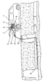
Nachstehend wird unter Bezugnahme auf die angeschlossenen Zeichnung ein Ausführungsbeispiel für eine Anordnung zum Durchführen des erfindungsgemäßen Verfahrens beschrieben. Die Zeichnung zeigt eine Vorrichtung zum Bestimmen des Längsprofils eines Kanalrohres zwischen zwei Kanalschächten.Hereinafter, an embodiment of an arrangement for carrying out the method according to the invention will be described with reference to the accompanying drawings. The drawing shows a device for determining the longitudinal profile of a sewer pipe between two manholes.
In einem Fahrzeug 1 ist eine Schlauchkassette 2 mit einem Schlauchvorrat für den Messschlauch von beispielsweise 250 m oder 60 m vorgesehen. An dem einen Ende des Schlauches 3, das im Ausführungsbeispiel bereits in dem Kanal 4 angeordnet ist, ist eine Messsonde 5 befestigt. Das andere Ende des über eine Haspel 6 geführten Schlauches endet in einem Ausgleichsbehälter 7, der oben mit einer Entlüftungsschraube 8 versehen ist. Dem Ausgleichsbehälter 7 ist eine Messeinrichtung 9, in welcher der Drucksensor für das Bestimmen des Druckes im beim Benützen der Vorrichtung geschlossenen Ausgleichsdruckgefäß 7 und ein Rechner für das Auswerten der Messdaten für den hydrostatischen Druck, den Druck im Ausgleichsbehälter 7 und die Temperatur untergebracht sind, vorgesehen. Die Messeinrichtung 9 enthält auch verschiedene Bedienungsschalter, Anzeigeeinrichtungen (Displays) und Steuereinrichtungen, die z.B. die Abstände zwischen den Messpunkten festlegen. Das Bewegen des Messschlauches 3 kann durch Drehen der Schlauchkassette(-haspel) 6 von Hand aus oder mit Hilfe eines Motors erfolgen. Um das Bewegen des Messschlauches 3 zu erleichtern, ist eine von Hand aus betätigbare und/oder motorangetriebene Vorschubeinrichtung 10 vorgesehen, der auch eine Einrichtung zum Messen der vor- bzw. zurückgezogenen Länge des Schlauches 3 zugeordnet sein kann. Der Messschlauch 3 läuft dann über Umlenkrollen 11,12,13 bis zur Sohle 14 des Kanals 4 und bis zur Messsonde 5. In der Messsonde 5 ist in deren Längsmitte ein Drucksensor und an deren vorderem Ende ein Temperatursensor untergebracht, wobei die Kabel für die Datenübertragung durch den Messschlauch 3 laufen. Beim Verwenden der beschriebenen Vorrichtung werden in jedem Messpunkt folgende Werte erfasst:
- Druck im Ausgleichsbehälter über der Flüssigkeitssäule
- Druck der Flüssigkeitssäule vom Ausgleichsbehälter auf den Druck-Sensor in der Messsonde,
- Temperatur im Drucksensor,
- Temperatur der Flüssigkeit,
- Temperatur der Luft und
- die Länge des gesamten Schlauchpaketes (beispielsweise 250 m oder 60 m).
- Pressure in the expansion tank above the liquid column
- Pressure of the liquid column from the expansion tank to the pressure sensor in the measuring probe,
- Temperature in the pressure sensor,
- Temperature of the liquid,
- Temperature of the air and
- the length of the entire hose package (for example 250 m or 60 m).
Diese Messwerte werden durch das Rechenprogramm zur Berechnung des Messergebnisses herangezogen.These measured values are used by the computer program to calculate the measurement result.
Mit dem beschriebenen Verfahren der Erfindung und mit Hilfe der ebenfalls beschriebenen erfindungsgemäßen Vorrichtung kann der Verlauf (das Längsprofil) eines Rohres 4 zwischen zwei Schächten 23 und 24 ermittelt werden.With the described method of the invention and with the help of the device according to the invention also described, the Course (the longitudinal profile) of a
Mit der beschriebenen Vorrichtung zum Bestimmen von Längsprofilen von Bauwerken kann auch ein System zur Dokumentation des Ortes und der Zeit der durchgeführten Messung kombiniert werden. Dies kann beispielsweise dadurch erfolgen, dass mit dem Rechenprogramm eine GPS-Vorrichtung und eine Echtzeituhr kombiniert werden.With the described apparatus for determining longitudinal profiles of structures, a system for documenting the location and time of the measurement performed can also be combined. This can be done, for example, by combining a GPS device and a real-time clock with the computer program.
Im Rahmen der Erfindung kann eine große Genauigkeit der Messungen von Druck und Temperatur erreicht werden, wenn in der Messsonde ein Drucksensor mit integriertem Temperatursensor verwendet wird.In the context of the invention, a high accuracy of the measurements of pressure and temperature can be achieved if a pressure sensor with integrated temperature sensor is used in the measuring probe.
Die erfassten Messwerte werden über eine serielle Datenleitung, die den (kombinierten) Druck-Temperatur-Sensor auch mit Energie versorgt, an den Rechner weitergeleitet. Über die Datenleitung können zusätzlich zu dem Wert für den gemessenen Druck auch die Temperatur des Sensors, der Sensortyp und die Sensornummer mitübertragen werden. So ist es möglich, den angeschlossenen Sensor durch den Rechner automatisch zu erkennen. Der Druck, der auf die mit ihrem oberen Ende im Ausgleichsgefäß angeordnete Flüssigkeitssäule wirkt, wird durch den dem Ausgleichsbehälter 7 zugeordneten Druck-Sensor erfasst und rechnerisch im Rechner berücksichtigt, wenn der vom Drucksensor erfasste hydrostatische Druck zum Ermitteln des Höhenabstandes zwischen Messpunkt und Referenzpunkt ausgewertet wird.The acquired measured values are forwarded to the computer via a serial data line which also supplies the (combined) pressure-temperature sensor with energy. In addition to the value for the measured pressure, the temperature of the sensor, the sensor type and the sensor number can also be transmitted via the data line. It is thus possible to automatically detect the connected sensor by the computer. The pressure acting on the liquid column arranged with its upper end in the expansion tank is detected by the pressure sensor associated with the
Die Dichte der verwendeten Flüssigkeit im Messschlauch zum Zeitpunkt der Messung und die von der Messsonde sowie von dem den Luftdruck erfassenden Druckmesser empfangenen Daten werden durch Zeit und Datum der eingebauten Echtzeituhr sowie den Koordinaten des integrierten GPS-Systems in einem RAM-Speicher im Rechner abgelegt. Über eine Schnittstelle können diese Daten über einen PC ausgelesen und ausgewertet werden.The density of the liquid used in the measuring tube at the time of measurement and the data received from the measuring probe and the air pressure gauge are stored in a RAM in the computer by the time and date of the built-in real-time clock and the coordinates of the integrated GPS system. Via an interface, these data can be read out and evaluated via a PC.
Von Vorteil ist es, wenn jede Messung für die spätere Auswertung mit einer individuellen Kennung für Projekt und Ort gekennzeichnet wird. Dies ist beispielsweise mit Hilfe des integrierten GPS-Systems und die integrierte Echtzeituhr möglich.It is advantageous if each measurement is marked for later evaluation with an individual identifier for project and location. This is possible, for example, with the help of the integrated GPS system and the integrated real-time clock.
Das erfindungsgemäße Verfahren und die erfindungsgemäße Vorrichtung erlauben folgende, beispielhaft genannten Einsatzmöglichkeiten:The method according to the invention and the device according to the invention allow the following application possibilities mentioned by way of example:
Der genaue Gefälleverlauf von Kanalrohren nach der Verschüttung des Rohrgrabens im Zuge der Bauabnahme kann ermittelt werden. Damit ist eine objektiv dokumentierte Beurteilung der Verlegqualität einwandfrei möglich. Bauchbildungen in den Rohrleitungen können festgestellt und innerhalb der Gewährleistungsfrist behoben werden. So können spätere Funktionsstörungen, die zusätzliche Pflege und Instandhaltungsaufwand verursachen, verhindert werden.The exact gradient of sewer pipes after the burial of the trench in the course of the construction acceptance can be determined. Thus, an objectively documented assessment of the laying quality is perfectly possible. Abdominal formations in the piping can be detected and repaired within the warranty period. This will prevent later malfunctions that cause additional care and maintenance.
Das Gefälle von Drainagesystemen in Mülldeponien kann exakt vermessen und damit sein Funktionszustand überprüft werden. Schlecht funktionierende Drainagesysteme können zu erheblichen Untergrundkontaminationen führen. Die Stabilität des Untergrundes und dessen genaue Beobachtung erlauben eine höhere Aufschüttung der Mülldeponie, wenn es zu keinem Absenken des Terrains und Gefährdung der Drainagen kommt. Höhere Aufschüttung spart kostbare Deponiefläche und im Grenzfall die Anlage einer neuen Deponie. Die gleichzeitige Messung der Temperatur lässt Rückschlüsse auf die Vergasung und sonstiger Reaktionen innerhalb des Müllkörpers zu.The gradient of drainage systems in landfills can be measured exactly and thus its functional status can be checked. Poorly functioning drainage systems can lead to considerable underground contamination. The stability of the ground and its close observation allow a higher landfill of the landfill, if there is no lowering of the terrain and endangerment of the drainage. Higher landfill saves valuable landfill space and, in the limit, the installation of a new landfill. The simultaneous measurement of the temperature allows conclusions about the gasification and other reactions within the garbage body.
Die Setzung von Erddämmen, Baukörpern von Strassen und Eisenbahnen können frühzeitig erkannt werden, da diese Setzungen im Untergrund nachgewiesen werden können, bevor sichtbare Auswirkungen an der Oberfläche auftreten. Eine Früherkennung von Sicherheitsrisiken kann Schäden vorbeugen bzw. vermeiden helfen.The settlement of earth dams, structures of roads and railroads can be detected early, as these settlements can be detected in the subsurface before visible effects on the surface occur. Early detection of security risks can help prevent or prevent damage.
Hangrutschungen können durch Kontrollmessungen frühzeitig erkannt werden, da sich eine Erdbewegung im Untergrund abzeichnet, bevor die ersten Anzeichen an der Oberfläche sichtbar werden.Landslides can be detected early by taking control measurements, as ground motion becomes apparent in the ground before the first signs become visible on the surface.
Zusammenfassend kann ein Ausführungsbeispiel der Erfindung wie folgt dargestellt werden:In summary, an embodiment of the invention can be represented as follows:
Zum Bestimmen des Längsprofils von im Erdreich verlegten Rohrleitungen wird der hydrostatische Druck einer Flüssigkeitssäule zwischen über die Länge des Bauwerkes verteilten Messpunkten und einem Referenzpunkt erfasst und aus den erfassten Werten der Höhenabstand des jeweiligen Messpunktes vom Referenzpunkt errechnet. Zum Ausführen dieses Verfahren wird ein mit Flüssigkeit gefüllter Schlauch 3 verwendet, der am unteren Ende einen Drucksensor zum Erfassen des hydrostatischen Druckes aufweist, und der an seinem obere Ende mit einem beim Ausführen der Messung geschlossenen Ausgleichsgefäß 7 für die Messflüssigkeit verbunden ist. Dem Ausgleichsgefäß 7 ist ein Drucksensor 9 zum Erfassen des Druckes zugeordnet. Der im Ausgleichsbehälter 7 herrschende Druck und die herrschende Temperatur, welche gesondert erfasst wird, und die Dichte der Messflüssigkeit beeinflusst, werden beim Auswerten der erfassten Werte für den hydrostatischen Druck berücksichtigt. Für jeden Messvorgang wird die Position des Messsystems und der Zeitpunkt des Messvorganges über GPS erfasst und registriert.To determine the longitudinal profile of pipelines laid in the ground, the hydrostatic pressure of a column of liquid is measured between measuring points distributed over the length of the structure and a reference point, and from the values recorded, the height distance of the respective measuring point calculated from the reference point. For carrying out this method, a liquid-filled
Claims (15)
- Method for determining the longitudinal profile of extended constructions, in particular constructions laid in the ground such as pipes and the like, in which the vertical distance of the construction from a reference point is determined at multiple measurement points distributed over the length of the construction, in that the hydrostatic pressure of a liquid column between the respective measurement point and the reference point is determined at each measurement point, and, taking into consideration the separately determined temperature of the liquid, the vertical distance of the respective measurement point from the reference point is calculated from the determined value for the hydrostatic pressure, characterised in that the hydrostatic pressure of a liquid column subjected to overpressure at its upper end is measured, wherein the upper end of the liquid column forms the reference point, and that the pressure acting on the upper end of the liquid column determined separately at the time of the measurement is taken into consideration in the calculation of the vertical distance from the measured values of the hydrostatic pressure.
- Method according to Claim 1, characterised in that the temperature of the liquid column is detected both at the measurement point and at the reference point.
- Method according to Claim 1 or 2, characterised in that the lower end of the liquid column is moved stepwise from measurement point to measurement point.
- Method according to Claim 3, characterised in that after moving the lower end of the liquid column on to the next measurement point, there is a pause before the next measurement of the hydrostatic pressure until the liquid column has steadied.
- Method according to one of Claims 1 to 4, characterised in that the time of each measurement is determined.
- Method according to one of Claims 1 to 5, characterised in that the location of each measurement is determined.
- Method according to one of Claims I to 6, characterised in that the pressure and temperature sensors are adjusted before the start of a measurement.
- Device for performing the method according to one of Claims 1 to 7, with a measurement hose (3) filled with a measuring liquid, which at the lower end has a pressure sensor installed in a measuring probe (5) provided on the lower end of the measurement hose (3), wherein the upper end of the hose (3) is connected to an equalising vessel (7) for the measuring liquid, and wherein a temperature sensor is installed at least in the measuring probe (5), characterised in that a sensor (9) is provided in the region of the closed equalising vessel (7) to determine the pressure in the equalising vessel (7).
- Device according to Claim 8, characterised in that the lines for forwarding data detected by the pressure sensor and by the temperature sensor on the measuring probe (5) are disposed in the interior of the measurement hose (3).
- Device according to Claim 8 or 9, characterised in that the equalising vessel (7) has a vent screw (8).
- Device according to one of Claims 8 to 10, characterised in that a reserve supply of measurement hose (3) of given length is wound on a hose reel (6).
- Device according to one of Claims 8 to 11, characterised in that a further temperature sensor is provided in the region of the reserve supply of measurement hose (3).
- Device according to one of Claims 8 to 12, characterised in that a motor- or hand-driven hose transport device (10) is provided to move the measurement hose (3).
- Device according to one of Claims 8 to 13, characterised in that the measurement hose (3) has an associated length measurement device for determining the displacement path of the hose (3) and thus of the measuring probe (5).
- Device according to one of Claims 8 to 14, characterised in that a computer is provided, into which the detected data for hydrostatic pressure, temperatures and atmospheric air temperature as well as possibly the time and location of the measurement determined by GPS are input, and with which the vertical distance between the respective measurement point and the reference point formed by the equalising vessel (7) is calculated.
Applications Claiming Priority (2)
| Application Number | Priority Date | Filing Date | Title |
|---|---|---|---|
| AT4792004 | 2004-03-18 | ||
| AT0047904A AT413000B (en) | 2004-03-18 | 2004-03-18 | METHOD FOR DETERMINING LENGTH PROFILES AND DEVICE FOR CARRYING OUT THE PROCESS |
Publications (2)
| Publication Number | Publication Date |
|---|---|
| EP1577640A1 EP1577640A1 (en) | 2005-09-21 |
| EP1577640B1 true EP1577640B1 (en) | 2007-09-19 |
Family
ID=34140206
Family Applications (1)
| Application Number | Title | Priority Date | Filing Date |
|---|---|---|---|
| EP04450238A Not-in-force EP1577640B1 (en) | 2004-03-18 | 2004-12-23 | Method and device for hydrostatic levelling |
Country Status (3)
| Country | Link |
|---|---|
| EP (1) | EP1577640B1 (en) |
| AT (2) | AT413000B (en) |
| DE (1) | DE502004005015D1 (en) |
Families Citing this family (3)
| Publication number | Priority date | Publication date | Assignee | Title |
|---|---|---|---|---|
| EP2259017B1 (en) * | 2009-05-25 | 2012-05-02 | Agisco S.r.l. | Differential level monitoring device |
| DE102009025701B4 (en) * | 2009-06-20 | 2016-02-18 | Ibak Helmut Hunger Gmbh & Co. Kg | Channel inspection device |
| CN110648504B (en) * | 2019-09-30 | 2020-12-25 | 中南大学 | Landslide disaster monitoring device and method |
Family Cites Families (3)
| Publication number | Priority date | Publication date | Assignee | Title |
|---|---|---|---|---|
| US5517869A (en) * | 1994-01-04 | 1996-05-21 | The Stanley Works | Hydrostatic altimeter error compensation |
| EP0797756A1 (en) * | 1994-12-12 | 1997-10-01 | DIETZSCH & ROTHE MSR-TECHNIK OHG | Level difference measurement apparatus |
| AT409671B (en) * | 2000-10-12 | 2002-10-25 | Taferner Marko | METHOD FOR DETERMINING LENGTH PROFILES AND DEVICE FOR CARRYING OUT THE METHOD |
-
2004
- 2004-03-18 AT AT0047904A patent/AT413000B/en not_active IP Right Cessation
- 2004-12-23 DE DE502004005015T patent/DE502004005015D1/en active Active
- 2004-12-23 EP EP04450238A patent/EP1577640B1/en not_active Not-in-force
- 2004-12-23 AT AT04450238T patent/ATE373811T1/en active
Also Published As
| Publication number | Publication date |
|---|---|
| AT413000B (en) | 2005-09-26 |
| ATE373811T1 (en) | 2007-10-15 |
| DE502004005015D1 (en) | 2007-10-31 |
| ATA4792004A (en) | 2005-02-15 |
| EP1577640A1 (en) | 2005-09-21 |
Similar Documents
| Publication | Publication Date | Title |
|---|---|---|
| DE19620656C2 (en) | Level measurement method | |
| DE60316828T2 (en) | BOHRLOCHLEITFÜHIGKEITSPROFILIERUNGSVORRICHTUNG | |
| DE69630736T2 (en) | Device with packer and method for sampling groundwater | |
| DE3009837C2 (en) | Device for laying pipes underground | |
| EP1727964B1 (en) | Advancement of pipe elements in the ground | |
| EP2543770A1 (en) | Method and device for measuring nozzle beams underground | |
| EP2352983A2 (en) | Rheometer for high-viscosity materials | |
| EP1577640B1 (en) | Method and device for hydrostatic levelling | |
| EP1197730B1 (en) | Method for determining longitudinal profiles and device therefor | |
| DE102007048978A1 (en) | Method for measuring function parameters of geothermal heat utilization arrangement, involves determining time and location dependent thermal coupling between geothermal heat utilization arrangement and surrounding | |
| DE102013205765B4 (en) | Quality assurance system for diaphragm wall joints | |
| DE10356696B3 (en) | Method and device for trenchless laying of pipelines | |
| DE10346890B4 (en) | Method and arrangement for the continuous detection of settlements on structures by means of a hydrostatic tube balance measuring system | |
| DE2810687C2 (en) | Device for checking the position of pipes laid in the ground | |
| DE202011107616U1 (en) | Device and lance device for pressing a borehole | |
| AT4576U1 (en) | METHOD FOR DETERMINING LENGTH PROFILES AND DEVICE FOR CARRYING OUT THE METHOD | |
| DE102014206042B4 (en) | Measuring device for a geothermal probe | |
| DE102016122032B4 (en) | Method and device for determining the tightness of vertically arranged earth protection pipes | |
| Schachinger et al. | Current research by ÖBB Infrastruktur AG on scale monitoring without track closures: Aktuelle Forschungen der ÖBB Infrastruktur‐AG zu Versinterungsmonitoring ohne Einschränkung des Eisenbahnbetriebs | |
| DE102009025701B4 (en) | Channel inspection device | |
| EP1387156B1 (en) | Method and device for determining the existences of leaks in blocking walls | |
| CH701566A1 (en) | Method for early recognition of building-site subsidence during construction of underground railways in urban area, involves transferring produced and previously evaluated measured values to persons working in working face area | |
| DE102012218338B3 (en) | Channel inspection device for measuring hydrostatic height of pipe in sewer, has pressure sensor connected with rinsing hose at end and formed in such manner that sensor detects hydrostatic pressure in hose to be locked by shut-off valve | |
| EP0732565A1 (en) | Measuring apparatus for determining the relative height of an object | |
| DE102010036411B4 (en) | Method for backfilling a borehole and arrangement therefor |
Legal Events
| Date | Code | Title | Description |
|---|---|---|---|
| PUAI | Public reference made under article 153(3) epc to a published international application that has entered the european phase |
Free format text: ORIGINAL CODE: 0009012 |
|
| AK | Designated contracting states |
Kind code of ref document: A1 Designated state(s): AT BE BG CH CY CZ DE DK EE ES FI FR GB GR HU IE IS IT LI LT LU MC NL PL PT RO SE SI SK TR |
|
| AX | Request for extension of the european patent |
Extension state: AL BA HR LV MK YU |
|
| 17P | Request for examination filed |
Effective date: 20050921 |
|
| AKX | Designation fees paid |
Designated state(s): AT BE BG CH CY CZ DE DK EE ES FI FR GB GR HU IE IS IT LI LT LU MC NL PL PT RO SE SI SK TR |
|
| GRAP | Despatch of communication of intention to grant a patent |
Free format text: ORIGINAL CODE: EPIDOSNIGR1 |
|
| GRAS | Grant fee paid |
Free format text: ORIGINAL CODE: EPIDOSNIGR3 |
|
| GRAA | (expected) grant |
Free format text: ORIGINAL CODE: 0009210 |
|
| AK | Designated contracting states |
Kind code of ref document: B1 Designated state(s): AT BE BG CH CY CZ DE DK EE ES FI FR GB GR HU IE IS IT LI LT LU MC NL PL PT RO SE SI SK TR |
|
| REG | Reference to a national code |
Ref country code: GB Ref legal event code: FG4D Free format text: NOT ENGLISH |
|
| REG | Reference to a national code |
Ref country code: CH Ref legal event code: EP |
|
| REF | Corresponds to: |
Ref document number: 502004005015 Country of ref document: DE Date of ref document: 20071031 Kind code of ref document: P |
|
| REG | Reference to a national code |
Ref country code: IE Ref legal event code: FG4D Free format text: LANGUAGE OF EP DOCUMENT: GERMAN |
|
| REG | Reference to a national code |
Ref country code: SE Ref legal event code: TRGR |
|
| PG25 | Lapsed in a contracting state [announced via postgrant information from national office to epo] |
Ref country code: FI Free format text: LAPSE BECAUSE OF FAILURE TO SUBMIT A TRANSLATION OF THE DESCRIPTION OR TO PAY THE FEE WITHIN THE PRESCRIBED TIME-LIMIT Effective date: 20070919 Ref country code: LT Free format text: LAPSE BECAUSE OF FAILURE TO SUBMIT A TRANSLATION OF THE DESCRIPTION OR TO PAY THE FEE WITHIN THE PRESCRIBED TIME-LIMIT Effective date: 20070919 |
|
| PG25 | Lapsed in a contracting state [announced via postgrant information from national office to epo] |
Ref country code: PL Free format text: LAPSE BECAUSE OF FAILURE TO SUBMIT A TRANSLATION OF THE DESCRIPTION OR TO PAY THE FEE WITHIN THE PRESCRIBED TIME-LIMIT Effective date: 20070919 |
|
| PG25 | Lapsed in a contracting state [announced via postgrant information from national office to epo] |
Ref country code: ES Free format text: LAPSE BECAUSE OF FAILURE TO SUBMIT A TRANSLATION OF THE DESCRIPTION OR TO PAY THE FEE WITHIN THE PRESCRIBED TIME-LIMIT Effective date: 20071230 Ref country code: GR Free format text: LAPSE BECAUSE OF FAILURE TO SUBMIT A TRANSLATION OF THE DESCRIPTION OR TO PAY THE FEE WITHIN THE PRESCRIBED TIME-LIMIT Effective date: 20071220 |
|
| REG | Reference to a national code |
Ref country code: IE Ref legal event code: FD4D |
|
| EN | Fr: translation not filed | ||
| PG25 | Lapsed in a contracting state [announced via postgrant information from national office to epo] |
Ref country code: GB Free format text: LAPSE BECAUSE OF FAILURE TO SUBMIT A TRANSLATION OF THE DESCRIPTION OR TO PAY THE FEE WITHIN THE PRESCRIBED TIME-LIMIT Effective date: 20070919 Ref country code: SK Free format text: LAPSE BECAUSE OF FAILURE TO SUBMIT A TRANSLATION OF THE DESCRIPTION OR TO PAY THE FEE WITHIN THE PRESCRIBED TIME-LIMIT Effective date: 20070919 Ref country code: PT Free format text: LAPSE BECAUSE OF FAILURE TO SUBMIT A TRANSLATION OF THE DESCRIPTION OR TO PAY THE FEE WITHIN THE PRESCRIBED TIME-LIMIT Effective date: 20080219 Ref country code: CZ Free format text: LAPSE BECAUSE OF FAILURE TO SUBMIT A TRANSLATION OF THE DESCRIPTION OR TO PAY THE FEE WITHIN THE PRESCRIBED TIME-LIMIT Effective date: 20070919 Ref country code: IS Free format text: LAPSE BECAUSE OF FAILURE TO SUBMIT A TRANSLATION OF THE DESCRIPTION OR TO PAY THE FEE WITHIN THE PRESCRIBED TIME-LIMIT Effective date: 20080119 |
|
| BERE | Be: lapsed |
Owner name: TAFERNER, MARKO Effective date: 20071231 |
|
| PG25 | Lapsed in a contracting state [announced via postgrant information from national office to epo] |
Ref country code: RO Free format text: LAPSE BECAUSE OF FAILURE TO SUBMIT A TRANSLATION OF THE DESCRIPTION OR TO PAY THE FEE WITHIN THE PRESCRIBED TIME-LIMIT Effective date: 20070919 |
|
| PLBE | No opposition filed within time limit |
Free format text: ORIGINAL CODE: 0009261 |
|
| STAA | Information on the status of an ep patent application or granted ep patent |
Free format text: STATUS: NO OPPOSITION FILED WITHIN TIME LIMIT |
|
| PG25 | Lapsed in a contracting state [announced via postgrant information from national office to epo] |
Ref country code: MC Free format text: LAPSE BECAUSE OF NON-PAYMENT OF DUE FEES Effective date: 20071231 Ref country code: DK Free format text: LAPSE BECAUSE OF FAILURE TO SUBMIT A TRANSLATION OF THE DESCRIPTION OR TO PAY THE FEE WITHIN THE PRESCRIBED TIME-LIMIT Effective date: 20070919 |
|
| 26N | No opposition filed |
Effective date: 20080620 |
|
| PG25 | Lapsed in a contracting state [announced via postgrant information from national office to epo] |
Ref country code: FR Free format text: LAPSE BECAUSE OF FAILURE TO SUBMIT A TRANSLATION OF THE DESCRIPTION OR TO PAY THE FEE WITHIN THE PRESCRIBED TIME-LIMIT Effective date: 20080523 Ref country code: BE Free format text: LAPSE BECAUSE OF NON-PAYMENT OF DUE FEES Effective date: 20071231 |
|
| PG25 | Lapsed in a contracting state [announced via postgrant information from national office to epo] |
Ref country code: IE Free format text: LAPSE BECAUSE OF FAILURE TO SUBMIT A TRANSLATION OF THE DESCRIPTION OR TO PAY THE FEE WITHIN THE PRESCRIBED TIME-LIMIT Effective date: 20070919 |
|
| PG25 | Lapsed in a contracting state [announced via postgrant information from national office to epo] |
Ref country code: EE Free format text: LAPSE BECAUSE OF FAILURE TO SUBMIT A TRANSLATION OF THE DESCRIPTION OR TO PAY THE FEE WITHIN THE PRESCRIBED TIME-LIMIT Effective date: 20070919 |
|
| PG25 | Lapsed in a contracting state [announced via postgrant information from national office to epo] |
Ref country code: SI Free format text: LAPSE BECAUSE OF FAILURE TO SUBMIT A TRANSLATION OF THE DESCRIPTION OR TO PAY THE FEE WITHIN THE PRESCRIBED TIME-LIMIT Effective date: 20070919 |
|
| PG25 | Lapsed in a contracting state [announced via postgrant information from national office to epo] |
Ref country code: CY Free format text: LAPSE BECAUSE OF FAILURE TO SUBMIT A TRANSLATION OF THE DESCRIPTION OR TO PAY THE FEE WITHIN THE PRESCRIBED TIME-LIMIT Effective date: 20070919 |
|
| REG | Reference to a national code |
Ref country code: CH Ref legal event code: PL |
|
| PG25 | Lapsed in a contracting state [announced via postgrant information from national office to epo] |
Ref country code: LU Free format text: LAPSE BECAUSE OF NON-PAYMENT OF DUE FEES Effective date: 20071223 Ref country code: BG Free format text: LAPSE BECAUSE OF FAILURE TO SUBMIT A TRANSLATION OF THE DESCRIPTION OR TO PAY THE FEE WITHIN THE PRESCRIBED TIME-LIMIT Effective date: 20071219 |
|
| PG25 | Lapsed in a contracting state [announced via postgrant information from national office to epo] |
Ref country code: TR Free format text: LAPSE BECAUSE OF FAILURE TO SUBMIT A TRANSLATION OF THE DESCRIPTION OR TO PAY THE FEE WITHIN THE PRESCRIBED TIME-LIMIT Effective date: 20070919 Ref country code: HU Free format text: LAPSE BECAUSE OF FAILURE TO SUBMIT A TRANSLATION OF THE DESCRIPTION OR TO PAY THE FEE WITHIN THE PRESCRIBED TIME-LIMIT Effective date: 20080320 |
|
| PG25 | Lapsed in a contracting state [announced via postgrant information from national office to epo] |
Ref country code: CH Free format text: LAPSE BECAUSE OF NON-PAYMENT OF DUE FEES Effective date: 20081231 Ref country code: LI Free format text: LAPSE BECAUSE OF NON-PAYMENT OF DUE FEES Effective date: 20081231 |
|
| PG25 | Lapsed in a contracting state [announced via postgrant information from national office to epo] |
Ref country code: IT Free format text: LAPSE BECAUSE OF NON-PAYMENT OF DUE FEES Effective date: 20071231 |
|
| PGFP | Annual fee paid to national office [announced via postgrant information from national office to epo] |
Ref country code: DE Payment date: 20121215 Year of fee payment: 9 |
|
| PGFP | Annual fee paid to national office [announced via postgrant information from national office to epo] |
Ref country code: SE Payment date: 20121221 Year of fee payment: 9 |
|
| PGFP | Annual fee paid to national office [announced via postgrant information from national office to epo] |
Ref country code: AT Payment date: 20121221 Year of fee payment: 9 Ref country code: NL Payment date: 20121217 Year of fee payment: 9 |
|
| REG | Reference to a national code |
Ref country code: DE Ref legal event code: R119 Ref document number: 502004005015 Country of ref document: DE |
|
| REG | Reference to a national code |
Ref country code: NL Ref legal event code: V1 Effective date: 20140701 |
|
| REG | Reference to a national code |
Ref country code: SE Ref legal event code: EUG |
|
| REG | Reference to a national code |
Ref country code: AT Ref legal event code: MM01 Ref document number: 373811 Country of ref document: AT Kind code of ref document: T Effective date: 20131223 |
|
| PG25 | Lapsed in a contracting state [announced via postgrant information from national office to epo] |
Ref country code: SE Free format text: LAPSE BECAUSE OF NON-PAYMENT OF DUE FEES Effective date: 20131224 |
|
| REG | Reference to a national code |
Ref country code: DE Ref legal event code: R119 Ref document number: 502004005015 Country of ref document: DE Effective date: 20140701 |
|
| PG25 | Lapsed in a contracting state [announced via postgrant information from national office to epo] |
Ref country code: NL Free format text: LAPSE BECAUSE OF NON-PAYMENT OF DUE FEES Effective date: 20140701 Ref country code: DE Free format text: LAPSE BECAUSE OF NON-PAYMENT OF DUE FEES Effective date: 20140701 |
|
| PG25 | Lapsed in a contracting state [announced via postgrant information from national office to epo] |
Ref country code: AT Free format text: LAPSE BECAUSE OF NON-PAYMENT OF DUE FEES Effective date: 20131223 |