EP1577592A1 - Gate valve - Google Patents
Gate valve Download PDFInfo
- Publication number
- EP1577592A1 EP1577592A1 EP04006114A EP04006114A EP1577592A1 EP 1577592 A1 EP1577592 A1 EP 1577592A1 EP 04006114 A EP04006114 A EP 04006114A EP 04006114 A EP04006114 A EP 04006114A EP 1577592 A1 EP1577592 A1 EP 1577592A1
- Authority
- EP
- European Patent Office
- Prior art keywords
- slide plate
- opening
- slide
- valve according
- housing
- Prior art date
- Legal status (The legal status is an assumption and is not a legal conclusion. Google has not performed a legal analysis and makes no representation as to the accuracy of the status listed.)
- Granted
Links
Images

Classifications
-
- F—MECHANICAL ENGINEERING; LIGHTING; HEATING; WEAPONS; BLASTING
- F16—ENGINEERING ELEMENTS AND UNITS; GENERAL MEASURES FOR PRODUCING AND MAINTAINING EFFECTIVE FUNCTIONING OF MACHINES OR INSTALLATIONS; THERMAL INSULATION IN GENERAL
- F16K—VALVES; TAPS; COCKS; ACTUATING-FLOATS; DEVICES FOR VENTING OR AERATING
- F16K3/00—Gate valves or sliding valves, i.e. cut-off apparatus with closing members having a sliding movement along the seat for opening and closing
- F16K3/02—Gate valves or sliding valves, i.e. cut-off apparatus with closing members having a sliding movement along the seat for opening and closing with flat sealing faces; Packings therefor
- F16K3/16—Gate valves or sliding valves, i.e. cut-off apparatus with closing members having a sliding movement along the seat for opening and closing with flat sealing faces; Packings therefor with special arrangements for separating the sealing faces or for pressing them together
- F16K3/20—Gate valves or sliding valves, i.e. cut-off apparatus with closing members having a sliding movement along the seat for opening and closing with flat sealing faces; Packings therefor with special arrangements for separating the sealing faces or for pressing them together by movement of the seats
- F16K3/207—Gate valves or sliding valves, i.e. cut-off apparatus with closing members having a sliding movement along the seat for opening and closing with flat sealing faces; Packings therefor with special arrangements for separating the sealing faces or for pressing them together by movement of the seats by means of hydraulic forces
-
- F—MECHANICAL ENGINEERING; LIGHTING; HEATING; WEAPONS; BLASTING
- F16—ENGINEERING ELEMENTS AND UNITS; GENERAL MEASURES FOR PRODUCING AND MAINTAINING EFFECTIVE FUNCTIONING OF MACHINES OR INSTALLATIONS; THERMAL INSULATION IN GENERAL
- F16K—VALVES; TAPS; COCKS; ACTUATING-FLOATS; DEVICES FOR VENTING OR AERATING
- F16K27/00—Construction of housing; Use of materials therefor
- F16K27/02—Construction of housing; Use of materials therefor of lift valves
-
- F—MECHANICAL ENGINEERING; LIGHTING; HEATING; WEAPONS; BLASTING
- F16—ENGINEERING ELEMENTS AND UNITS; GENERAL MEASURES FOR PRODUCING AND MAINTAINING EFFECTIVE FUNCTIONING OF MACHINES OR INSTALLATIONS; THERMAL INSULATION IN GENERAL
- F16K—VALVES; TAPS; COCKS; ACTUATING-FLOATS; DEVICES FOR VENTING OR AERATING
- F16K3/00—Gate valves or sliding valves, i.e. cut-off apparatus with closing members having a sliding movement along the seat for opening and closing
- F16K3/02—Gate valves or sliding valves, i.e. cut-off apparatus with closing members having a sliding movement along the seat for opening and closing with flat sealing faces; Packings therefor
- F16K3/0281—Guillotine or blade-type valves, e.g. no passage through the valve member
-
- F—MECHANICAL ENGINEERING; LIGHTING; HEATING; WEAPONS; BLASTING
- F16—ENGINEERING ELEMENTS AND UNITS; GENERAL MEASURES FOR PRODUCING AND MAINTAINING EFFECTIVE FUNCTIONING OF MACHINES OR INSTALLATIONS; THERMAL INSULATION IN GENERAL
- F16K—VALVES; TAPS; COCKS; ACTUATING-FLOATS; DEVICES FOR VENTING OR AERATING
- F16K3/00—Gate valves or sliding valves, i.e. cut-off apparatus with closing members having a sliding movement along the seat for opening and closing
- F16K3/30—Details
- F16K3/314—Forms or constructions of slides; Attachment of the slide to the spindle
Definitions
- the invention relates to a slide valve having the features of the preamble of Patent claim 1, as well as on a coating system with such a valve.
- valves are often installed in continuous coating systems, which are used for Coating flexible tape substrates, e.g. As plastic films, magnetic tapes, films etc., or even of rigid substrates such as plastic or glass panes, serve in a vacuum.
- Rigid substrates lie on rolls and pass between loading and unloading stations transported, which in turn are regularly ventilated.
- Such continuous coating systems are basically subdivided into modules (Loading, coating and Auslademodul) arranged successively and are connected by openings through which the substrate in the next following Module is guided.
- valves do not have to switch constantly back and forth, but are ultimately only used or activated during charge changes or other system downtime, but then have to seal the pressure difference between atmospheric pressure and vacuum.
- the installation position of these valves is inevitably directly in the area of the substrate transport systems.
- these transport systems are usually designed as roller conveyors with defined roller distances. Due to ever-increasing customer requirements, such as ever smaller substrate dimensions and increasing throughput speeds, it is necessary to shorten the distances between the individual transport rollers to each other accordingly. This fact requires a very narrow separating valve, since it has to be accommodated between two transport rollers, with one transport roller in one module (upstream) and the next transport roller in the other module (downstream).
- the generic document DE 198 57 201 A1 describes such a flat-building Gate valve for simultaneously shutting off or releasing two between two vacuum chambers provided, aligned passage openings, which has a low Height and have a large width.
- the valve is for continuous systems for coating designed from large glass formats.
- a short-stroke further fluidic (pneumatic) closing drive the pressurized after the spool plates have been moved to their working position and the two plates spread apart until they are in their closed position at the same time abut against each associated with them, surrounding the openings sealing surfaces and the Close openings thus tightly.
- the reaction forces of the closing drive are each removed over the opposite valve plate.
- U.S. Patent No. 4,157,169 discloses another, in principle very similar to that discussed above constructed lock valve, the opening and closing two round passages is provided.
- the invention is based on the object, a particularly flat-built slide valve create that for the installation in particular between two close successive roles a continuous coating plant is suitable and nevertheless very high pressure differences endures and reliably seals, with its moving parts as simple as possible should be built.
- the invention describes a valve, preferably either as a maintenance valve or as Valve with a small number of cycles is used, so are not switched very often got to.
- the structure is similar to a slide valve with a very flat design (max. 50mm), which is vacuum-tight on both sides. Due to its active principle, it is also possible, also slit-shaped To reliably seal openings with a very long length. Likewise, the valve is in able to compensate for large-wave unevenness of the opening to be closed achieved due to the very flexible design of its slide plate.
- the plate is closed by means of a housing-fixed closing drive pressed down a housing wall, on which the corresponding sealing surface is located.
- Reaction forces of the closing drive are thus advantageously directly within the fixed housing ablated.
- the closing movement of the valve according to the invention or its slide plate runs angular, preferably at right angles to the adjusting movement between the rest position and the working position of its slide plate.
- the slide valve according to the invention is mirror-symmetrical with each built two closing drives and two sealing surfaces, making it two different Closed positions can take.
- the slide valve depending on the direction of the pressure difference across the slide plate be selectively closed so that the respective greater pressure on one Side the sealing effect even stronger.
- the slide plate is pendulum suspended in the sealing direction, thus in the adjusting movements between resting and working position substantially free of friction; this reduces or also avoids wear on the sealing surfaces.
- “commuting” is no Agility over longer distances or strokes to understand. Rather, the slide plate has transverse to the direction of adjustment between rest and working position certain degrees of freedom, which are rather to be regarded as a limited side game. It can be reliable
- the function of the slide valve is sufficient, the slide plate by a few tenths Millimeter from their work in their respective sealing position to move or deflect.
- the closing drives are preferably activated by fluid pressure, d. H. they include at least one provided with a pressure port closed space with at least a movable wall. It is not essential that these locking drives themselves completely to extend the entire opening, but you can basically provide a subdivided into several sections or individual actuators closing drive (as similarly described in the generic state of the art). In this Execution case is of course a uniform distribution of the individual drive parts along to the extent of the opening to be closed, although not necessarily functionally necessary.
- annularly closed, tubular tire-like design is particularly preferred the closing drive, especially since it is in this version as an additional Apply sealing ring to the smooth-walled slide plate and thus z.
- the closing drive also the (unwanted) Application of coating particles coming from the vacuum chamber into the opening and can get to the valve (also called overspray) on the actual sealing rings prevented.
- the closing drives and the corresponding seals are arranged on concentric parallel tracks around the openings to be closed, whereby the closing drives can be arranged outside or within the surfaces circumscribed by these seals.
- the closing drives protect the sealing rings, as already mentioned, as far as possible from unwanted deposits.
- this version with a simple, smooth slide plate has the big one Advantage that long-wave unevenness of the sealing surfaces by intrinsic flexibility of the large area and pressed over the entire circumference of the opening to be closed Sliding plate can be compensated, so that even slight distortion of the sealing seat due to dimensional or surface deviations or uneven tightening of Screws, etc., not necessarily to leaks of the slide valve according to the invention to lead.
- very large, slot-like openings of several Meters wide, the z For example, in continuous coating systems for more than 3 m wide glass plates are common and necessary, certainly against the pressure differences between vacuum and atmospheric pressure to be completed.
- each one Closing drive forms a mixture of drive member and sealing surface.
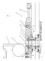
- This cross-section shows the transition between two modules 1, 2 of a continuous coating plant. It is assumed that (here only by a horizontal transport plane T) substrates undergo this transition from left to right, wherein they are supported by closely spaced rollers 3 (in the relatively short shown section of the system, however, only a role 3 is shown schematically).
- an opening 4 is provided which is perpendicular to Drawing plane can have significantly larger dimensions than in their visible here Height, so can be considered as slit-shaped, but overall with the smallest possible free cross section is executed. It just has to be in the preferred use case be large enough to pass through flat glass plates more than 3 m wide.
- the slide valve 5 initially comprises a housing 6 with two housing parts 6.1 and 6.2. It is understood that this housing 6 is very well sealed in itself, as far as it is composed of different components. One recognizes here z. B. a sealing ring 6D in the joint between the two housing parts 6.1 and 6.2, and another sealing ring 6D in the joint between the housing part 6.2 and the wall of the transition to which the housing 6 is clamped in the region of the opening 4 total.
- the housing 6 is also penetrated in total by the opening 4 or it has a channel which forms a continuation of said opening 4 with a constant free cross-section.
- this slide valve does not have to be arranged between the two modules 1 and 2, but that its housing 6 is screwed on one side to the wall of the module 1. This will be a certain Reduction of the distance between the two modules possible. Nevertheless, it is natural depending on the type of plant and available space, the valve according to the invention also possible to install in a joint, a gap or transition between two modules, wherein its channel between the two directly interconnected openings of the Modules would come to rest.
- the two housing parts 6.1 and 6.2 form between them a guide slot 6 S, in the a slide plate 7 oscillating, d. H. seen in the normal direction to their major surfaces is stored with little lateral play. It hangs on a not shown translatory actuator 7A.
- actuator 7A is with the slide plate 7 in a suitable manner connected to allow their lateral deflections.
- This connection between the actuator 7A and the slide plate 7 penetrates the housing 6. Special sealing measures are required at this point only if the actuator 7A itself should be outside the module 1 or outside the evacuable volume.
- the (vertical) guide slot 6S extends, as well as the recorded in it Slide plate, transverse to the (horizontal) axis of the opening 4, in sections on both sides of the transport plane T. Its substantial length portion is above the Transport level T, but is also provided below a short section.
- the slide plate 7 by means of the actuator 7A out and forth adjustable, between a rest position (see Fig. 2), in which the opening is completely open and substrates can pass through it, and the work shown here is or closed position in which the slide plate 7, the slot-shaped opening 4 completely covers.
- the slide plate 7 In the rest position, the slide plate 7 is completely in the upper part of the guide slot 6S recorded, in the working position their lower edge dives like a blade in the lower Section of the guide slot 6S, while its upper part still in the upper Section remains. It is essential that the slide plate 7 everywhere the edge of the opening 4 covered.
- the reciprocating movement of the slide plate 7 by means of the actuator 7A takes place first free, without too tight guide in the guide slot 6S, d. H. also with negligible Friction. Consequently, the actuator 7A does not have to apply too high actuating forces.
- He may be, for example, a pneumatic or hydraulic lift cylinder, a rack drive, or an electromagnetic linear motor. He does not have to run a long stroke (a few inches) and the sealing plate only has to be relatively coarse in its working position can position.
- the actuator 7A is representative of a plurality of similar, Synchronously controllable actuators is, which are used when needed, if the Slide plate 7 extends possibly over several meters in length perpendicular to the plane of the drawing.
- a first closing drive 8 is inserted in the left half of the housing 6.1. He is preferable designed as an inflatable seal, which in a circumferential annular groove of the housing wall is inserted and in turn surrounds the entire circumference of the opening 4. Functionally corresponds with this closing drive 8, a ring seal 9, in the wall of the opposite Housing half 6.2 is also embedded in an annular groove and also the opening 4 completely surrounds.
- the closing drive 8 in the illustrated embodiment is in the opposite lying wall of the housing part 6.2, a second closing drive 10 of the same type as the Closed drive 8 embedded. It is within the circumscribed by the ring seal 9 Area.
- the closing drive 10 in turn functionally corresponds to a ring seal 11, the in the wall of the housing part 6.1 is inserted, again exactly opposite the ring seal 9, and surrounds the closing drive 8.
- the closing drives 8 and / or 10 as uniform, schlauchsammlungartig circulating chambers interpret. It is special also conceivable, the closing drives instead of revolving only as two parallel elongated sections on both sides of the opening 4. Even that would be even more essential Protection of the sealing rings against overspray guaranteed.
- only one of the closing drives can be provided, if only in one direction, the slide plate is designed to seal.
- the circumferential configuration of the closing drives 8 and 10 discussed here has the Advantage that they with appropriate design of their outer surfaces as secondary seals on the smooth surface of the slide plate 7 abut and thus the sealing effect of the sealing rings 9 or 11 still support as long as their interior is pressurized.
- a strip 12 of permanently elastic material interchangeably attached He closes the section of the guide slot 6S below the transport plane and prevents the falling of particles in the lower portion of the guide slot 6S. It is designed as a lip seal divided and leaves the slide plate 7 unhindered immerse yourself when it is put into its working position.
- sealing rings 9 and 11 and the closing drives 8 and 10 respectively are far in the respective housing walls embedded or optionally by negative pressure Retractable are that damage or even friction due to contacts with the slide plate 7 during their Umstellieri between rest and working position can be excluded.
- the slide plate 7 in comparison with the thicknesses of the housing parts 6.1 and 6.2 can be kept quite thin and light. In cooperation with a uniform distribution as possible of the closing forces acting from the closing drives 8 and 10, respectively, the slide plate 7 will thus be able to conform exactly to the course of the sealing rings 9 and 11, even if these should have slight long-wave deviations from the ideal sealing plane. As a rule, the slide plate 7 is then actuated by the drive 7A when the pressure in both modules to be separated from each other is (still or again) the same, ie, for. B. atmospheric pressure on both sides or vacuum on both sides.
- closing drives 8 and 10 are the actual valve drives, which ensure the sealing function.
- the actuator 7A is for positioning only the slide plate provided in their general working position, regardless of the Direction of pressure difference.
- the actual sealing function of the slide valve 6 or the one-piece slide plate 7 are used here in both directions, by optionally one of the closing drives 8 or 10 is actuated.
- the exemplary embodiment of the slide valve described and shown here 6 is constructed mirror-symmetrically in its parts with sealing function and therefore in both directions a high pressure difference across the plane of the slide plate 7 endure can.
- the actuator can 7A return the slide plate to its rest position. Possibly. can solve the Slide plate 7 of the sealing rings 9 or 11 by means not shown here leaf or Disc springs are supported, of course, the restoring force of the closing drives must be overcome.
- slide valve according to the invention even if it is based on a preferred embodiment for continuous coating systems for large individual substrates has been described, regardless of this use also used elsewhere can be.
Abstract
Description
Die Erfindung bezieht sich auf ein Schieberventil mit den Merkmalen des Oberbegriffs des
Patentanspruchs 1, sowie auf eine Beschichtungsanlage mit einem derartigen Ventil.The invention relates to a slide valve having the features of the preamble of
Einschlägige Ventile werden häufig in Durchlaufbeschichtungsanlagen eingebaut, die zum Beschichten von flexiblen Bandsubstraten, z. B. Kunststofffolien, Magnetbändern, Filmen etc., oder auch von starren Substraten wie Kunststoff- oder Glasscheiben, im Vakuum dienen.Relevant valves are often installed in continuous coating systems, which are used for Coating flexible tape substrates, e.g. As plastic films, magnetic tapes, films etc., or even of rigid substrates such as plastic or glass panes, serve in a vacuum.
Hierbei ist es in gewissen Zeitabständen erforderlich, die in Ballen- oder Trommelform gewickelten Bandsubstrate oder Folien in die Anlage einzubringen und sie auf einer Lagerachse aufzunehmen, so dass das Bandsubstrat während des Beschichtungsdurchlaufs von diesem Ballen abgewickelt werden kann.In this case, it is necessary at certain intervals, wrapped in bale or drum shape To bring tape substrates or foils into the plant and put them on a bearing axis so that the tape substrate during the coating pass of this Bales can be handled.
Jenseits/stromab der Beschichtungskammer(n) ist eine weitere Achse mit einer Aufwickeltrommel vorgesehen, auf welche das beschichtete Bandsubstrat wieder aufgewickelt wird.Beyond / downstream of the coating chamber (s) is another axis with a take-up drum provided on which the coated tape substrate is wound up again.
Starre Substrate werden auf Rollen liegend und durchlaufend zwischen Einlade- und Ausladestationen transportiert, die ihrerseits regelmäßig belüftet sind.Rigid substrates lie on rolls and pass between loading and unloading stations transported, which in turn are regularly ventilated.
Solche Durchlaufbeschichtungsanlagen sind hierbei grundsätzlich in Module unterteilt (Einlade-, Beschichtungs- und Auslademodul), die aufeinander folgend angeordnet und durch Öffnungen miteinander verbunden sind, durch welche das Substrat in das nächstfolgende Modul geführt wird. Such continuous coating systems are basically subdivided into modules (Loading, coating and Auslademodul) arranged successively and are connected by openings through which the substrate in the next following Module is guided.
Es kann erforderlich sein, allein ein Beschichtungsmodul zu fluten, z. B. um eine Sputterkathode auszutauschen oder sonstige Wartungsarbeiten auszuführen, während die daran angrenzenden Module ihr aktuelles Druckniveau beibehalten können.It may be necessary to flood a coating module alone, e.g. B. to a sputtering cathode replace or perform any other maintenance while doing so adjacent modules can maintain their current pressure level.
Man sieht deshalb schaltbare Schleusenventile zwischen den einzelnen Modulen vor. Damit wird das nach Eingriffen in im Vakuum arbeitende Module der Anlage wieder zu entlüftende Volumen deutlich verringert, da nur noch einzelne Stationen belüftet werden und die anderen Stationen stets im evakuierten Zustand verbleiben können. Natürlich kann aber bei Bedarf die gesamte Anlage belüftet werden.It therefore provides switchable lock valves between the individual modules. In order to This will be vented again after intervening in working in vacuum modules of the system Volume significantly reduced, since only individual stations are ventilated and the other stations can always remain in the evacuated state. Of course, but at Need the entire system to be ventilated.
Diese Ventile müssen also nicht ständig hin und her schalten, sondern werden letztlich nur
bei Ladungswechseln oder sonstigen Anlagenstillständen gebraucht bzw. aktiviert, müssen
dann aber die Druckdifferenz zwischen Atmosphärendruck und Vakuum abdichten.
Die Einbauposition dieser Ventile liegt zwangsläufig direkt im Bereich der Substrattransportsysteme.
Diese Transportsysteme werden bei Glasbeschichtungsanlagen in der Regel als
Rollengänge mit definierten Rollenabständen ausgeführt. Durch ständig wachsende Kundenanforderungen,
wie immer kleiner werdende Substratmaße und steigende Durchlaufgeschwindigkeiten,
wird es notwendig, die Abstände der einzelnen Transportrollen zueinander
entsprechend zu verkürzen. Diese Tatsache erfordert ein sehr schmal bauendes Trenn- oder
Schleusenventil, da man es zwischen zwei Transportrollen unterbringen muss, wobei die
eine Transportrolle in dem einen Modul (stromauf) und die nächste Transportrolle in dem
anderen Modul (stromab) liegt.Thus, these valves do not have to switch constantly back and forth, but are ultimately only used or activated during charge changes or other system downtime, but then have to seal the pressure difference between atmospheric pressure and vacuum.
The installation position of these valves is inevitably directly in the area of the substrate transport systems. In glass coating systems, these transport systems are usually designed as roller conveyors with defined roller distances. Due to ever-increasing customer requirements, such as ever smaller substrate dimensions and increasing throughput speeds, it is necessary to shorten the distances between the individual transport rollers to each other accordingly. This fact requires a very narrow separating valve, since it has to be accommodated between two transport rollers, with one transport roller in one module (upstream) and the next transport roller in the other module (downstream).
Das gattungsbildende Dokument DE 198 57 201 A1 beschreibt ein solches flach bauendes Schleusenventil zum gleichzeitigen Absperren oder Freigeben von zwei zwischen zwei Vakuumkammern vorgesehenen, miteinander fluchtenden Durchlauföffnungen, die eine geringe Höhe und eine große Breite haben. Das Ventil ist für Durchlaufanlagen zum Beschichten von großen Glasformaten konzipiert.The generic document DE 198 57 201 A1 describes such a flat-building Gate valve for simultaneously shutting off or releasing two between two vacuum chambers provided, aligned passage openings, which has a low Height and have a large width. The valve is for continuous systems for coating designed from large glass formats.
Es hat zum Verschließen der Öffnungen zwei einander gegenüber liegende Ventil- oder Schieberplatten. Letztere bilden eine konstruktive Einheit, die mithilfe eines ersten Stellantriebs translatorisch zwischen einer Ruhestellung, in der die Öffnungen frei sind, und einer Arbeitsstellung hin und her stellbar ist. In der Arbeitsstellung liegen die Schieberplatten zwischen den Öffnungen und überdecken diese vollständig.It has to close the openings two opposing valve or Slide plates. The latter form a constructive unit, using a first actuator translationally between a rest position in which the openings are free, and one Working position is back and forth adjustable. In the working position are the slide plates between the openings and cover them completely.
Zwischen den beiden Schieberplatten, die im Ruhezustand federnd aufeinander gedrückt werden und die Öffnungen auch in der Arbeitsstellung zunächst noch nicht dicht verschließen, ist ein kurzhubiger weiterer fluidischer (pneumatischer) Schließantrieb angeordnet, der nach dem Verbringen der Schieberplatten in ihre Arbeitsstellung mit Druck beaufschlagt wird und die beiden Platten auseinander spreizt, bis sie in ihrer Schließstellung gleichzeitig gegen jeweils ihnen zugeordnete, die Öffnungen umgebende Dichtflächen anliegen und die Öffnungen somit dicht verschließen. Die Reaktionskräfte des Schließantriebs werden jeweils über die gegenüberliegende Ventilplatte abgetragen.Between the two slide plates, which are pressed against each other at rest are not yet tightly close the openings even in the working position, is arranged a short-stroke further fluidic (pneumatic) closing drive, the pressurized after the spool plates have been moved to their working position and the two plates spread apart until they are in their closed position at the same time abut against each associated with them, surrounding the openings sealing surfaces and the Close openings thus tightly. The reaction forces of the closing drive are each removed over the opposite valve plate.
Zum Öffnen dieses Ventils wird die Druckbeaufschlagung des Stellantriebs aufgehoben; er
kann zusätzlich in Umkehrrichtung mit Unterdruck beaufschlagt werden, um die auf die
Schieberplatten rückstellend einwirkenden Federkräfte zu unterstützen.
Bei diesem bekannten Ventil sind elastische Dichtringe in Nuten der Schieberplatten eingelegt.To open this valve, the pressurization of the actuator is canceled; In addition, it can be acted upon in the reverse direction with negative pressure in order to support the resiliently acting on the slide plates spring forces.
In this known valve elastic sealing rings are inserted in grooves of the slide plates.
US-PS 4,157,169 offenbart ein anderes, prinzipiell sehr ähnlich wie das vorstehend erörterte aufgebautes Schleusenventil, das zum Öffnen und Schließen zweier runder Durchlauföffnungen vorgesehen ist. Hier sind keine weichelastischen Dichtringe, sondern Ventilsitze in Gestalt von Weichmetallauflagen an den Rändern der Öffnungen vorgesehen, mit denen an den Schieberplatten angeordnete Dichtringe, ebenfalls aus Weichmetall, korrespondieren.U.S. Patent No. 4,157,169 discloses another, in principle very similar to that discussed above constructed lock valve, the opening and closing two round passages is provided. Here are not soft elastic sealing rings, but valve seats in Shape of soft metal supports provided at the edges of the openings with which the slide plates arranged sealing rings, also made of soft metal, correspond.
Bei beiden Lösungen müssen der fluidische Schließantrieb der Schieberplatten und folglich auch dessen Zufuhrleitungen bei den Umschaltvorgängen zwischen Ruhe- und Arbeitsstellungen hin und her mitbewegt werden. Folglich sind die beweglichen Schieberteile verhältnismäßig kompliziert und aufwändig.In both solutions, the fluidic closing drive of the slide plates and consequently also its supply lines in the switching between resting and working positions be moved back and forth. Consequently, the movable slide parts are relatively complicated and elaborate.
DE 44 46 946 C1 erörtert ein weiteres ähnliches Schieberventil mit einem aus einer Ruhestellung in eine Arbeitsstellung stellbaren Ventilteller in Gestalt einer einfachen Platte. Hinsichtlich des dichtenden Andrückens dieses Ventiltellers an seinen Ventilsitz und der Bauart der verwendeten Dichtungen schweigt sich dieses Dokument aus. Außerdem hat dieses Schieberventil nur eine Wirkrichtung, da nur auf einer Seite der Schieberplatte ein Ventilsitz vorgesehen ist.DE 44 46 946 C1 discusses another similar slide valve with one from a rest position in a working position adjustable valve plate in the form of a simple plate. Regarding the sealing pressing of this valve disc to its valve seat and the type the seals used are silent on this document. Besides, this one has Slide valve only one effective direction, since only on one side of the slide plate, a valve seat is provided.
Der Erfindung liegt die Aufgabe zu Grunde, ein besonders flach bauendes Schieberventil zu schaffen, das für den Einbau insbesondere zwischen zwei nahe aufeinander folgenden Rollen einer Durchlaufbeschichtungsanlage geeignet ist und gleichwohl sehr hohe Druckdifferenzen erträgt und zuverlässig abdichtet, wobei seine beweglichen Teile möglichst einfach aufgebaut sein sollen.The invention is based on the object, a particularly flat-built slide valve create that for the installation in particular between two close successive roles a continuous coating plant is suitable and nevertheless very high pressure differences endures and reliably seals, with its moving parts as simple as possible should be built.
Diese Aufgabe wird erfindungsgemäß mit den Merkmalen des Patentanspruchs 1 gelöst.
Der nebengeordnete Patentanspruch 17 bezieht sich auf eine mit dem erfindungsgemäßen
Schieberventil ausgestattete Anlage. Die Merkmale der jeweils nachgeordneten Unteransprüche
geben vorteilhafte Weiterbildungen der Erfindung an.This object is achieved with the features of
Die Erfindung beschreibt ein Ventil, das vorzugsweise entweder als Wartungsventil oder als Ventil mit kleiner Zykluszahl eingesetzt wird, also nicht sehr häufig geschaltet werden muss. Der Aufbau ähnelt dem eines Schieberventils mit sehr flacher Bauweise (max. 50mm), das beidseitig vakuumdicht ist. Durch sein Wirkprinzip ist es möglich, auch spaltförmige Öffnungen mit sehr großer Länge zuverlässig abzudichten. Ebenso ist das Ventil in der Lage, großwellige Unebenheiten der zu verschließenden Öffnung auszugleichen, erreicht durch die sehr flexible Bauart seiner Schieberplatte.The invention describes a valve, preferably either as a maintenance valve or as Valve with a small number of cycles is used, so are not switched very often got to. The structure is similar to a slide valve with a very flat design (max. 50mm), which is vacuum-tight on both sides. Due to its active principle, it is also possible, also slit-shaped To reliably seal openings with a very long length. Likewise, the valve is in able to compensate for large-wave unevenness of the opening to be closed achieved due to the very flexible design of its slide plate.
Bei dem erfindungsgemäßen Ventil wird eine in einem Gehäuse befindliche, einfache Platte aus einer Ruhestellung vorzugsweise mittels eines beliebigen Fremdkraft-Stellantriebes in seine Arbeitsstellung vor die zu verschließende Öffnung gebracht. Grundsätzlich wäre auch manuelles Umstellen der Schieberplatte zwischen Ruhe- und Arbeitsstellung möglich, wobei diese Option zusätzlich zu einem vorhandenen Stellantrieb für Notfälle vorbehalten sein kann.In the valve according to the invention is located in a housing, a simple plate from a rest position preferably by means of any foreign-power actuator in placed his working position in front of the opening to be closed. Basically, too Manual adjustment of the slide plate between resting and working position possible, where this option may be reserved in addition to an existing emergency actuator can.
Zum Schließen der Öffnung wird die Platte mittels eines gehäusefesten Schließantriebs zu einer Gehäusewand hin gedrückt, auf der sich die korrespondierende Dichtfläche befindet. To close the opening, the plate is closed by means of a housing-fixed closing drive pressed down a housing wall, on which the corresponding sealing surface is located.
Reaktionskräfte des Schließantriebs werden also vorteilhaft direkt innerhalb des festen Gehäuses abgetragen.Reaction forces of the closing drive are thus advantageously directly within the fixed housing ablated.
Die Schließbewegung des erfindungsgemäßen Ventils bzw. seiner Schieberplatte verläuft winklig, vorzugsweise rechtwinklig zu der Stellbewegung zwischen der Ruhestellung und der Arbeitsstellung seiner Schieberplatte.The closing movement of the valve according to the invention or its slide plate runs angular, preferably at right angles to the adjusting movement between the rest position and the working position of its slide plate.
Wie beim Stand der Technik differenziert man auch beim erfindungsgemäßen Schieberventil zwischen dem Stellantrieb und den eigentlichen Schließantrieben.As in the prior art, differentiation is also made in the slide valve according to the invention between the actuator and the actual closing drives.
Besonders bevorzugt wird das erfindungsgemäße Schieberventil spiegelsymmetrisch mit je zwei Schließantrieben und zwei Dichtflächen aufgebaut, so dass es zwei unterschiedliche Schließstellungen einnehmen kann. In dieser vorteilhaften Ausgestaltung der Erfindung kann das Schieberventil je nach Richtung der auftretenden Druckdifferenz über die Schieberplatte selektiv immer so geschlossen werden, dass der jeweils größere Druck auf einer Seite die Dichtwirkung noch verstärkt.Particularly preferably, the slide valve according to the invention is mirror-symmetrical with each built two closing drives and two sealing surfaces, making it two different Closed positions can take. In this advantageous embodiment of the invention can the slide valve depending on the direction of the pressure difference across the slide plate be selectively closed so that the respective greater pressure on one Side the sealing effect even stronger.
Die Schieberplatte ist in Dichtrichtung pendelnd aufgehängt, folglich bei den Stellbewegungen zwischen Ruhe- und Arbeitsstellung im Wesentlichen frei von Reibung; dies mindert oder vermeidet auch Verschleiß an den Dichtflächen. Unter "pendelnd" ist allerdings keine Beweglichkeit über längere Wege oder Hübe zu verstehen. Vielmehr hat die Schieberplatte quer zu der Stellrichtung zwischen Ruhe- und Arbeitsstellung gewisse geringe Freiheitsgrade, die eher als begrenztes seitliches Spiel anzusehen sind. Es kann für eine zuverlässige Funktion des Schieberventils vollauf genügen, die Schieberplatte um einige wenige Zehntel Millimeter aus ihrer Arbeits- in ihre jeweilige Dichtstellung zu bewegen bzw. auszulenken.The slide plate is pendulum suspended in the sealing direction, thus in the adjusting movements between resting and working position substantially free of friction; this reduces or also avoids wear on the sealing surfaces. Under "commuting", however, is no Agility over longer distances or strokes to understand. Rather, the slide plate has transverse to the direction of adjustment between rest and working position certain degrees of freedom, which are rather to be regarded as a limited side game. It can be reliable The function of the slide valve is sufficient, the slide plate by a few tenths Millimeter from their work in their respective sealing position to move or deflect.
Die Schließantriebe sind vorzugsweise durch Fluiddruck aktivierbar, d. h. sie umfassen mindestens einen mit einem Druckanschluss versehenen geschlossenen Raum mit mindestens einer beweglichen Wand. Es ist nicht unbedingt erforderlich, diese Schließantriebe sich vollständig um die gesamte Öffnung erstrecken zu lassen, sondern man kann grundsätzlich einen in mehrere Abschnitte oder einzelne Stellantriebe unterteilten Schließantrieb vorsehen (wie es ähnlich auch im gattungsbildenden Stand der Technik beschrieben wird). In diesem Ausführungsfall ist natürlich eine gleichmäßige Verteilung der einzelnen Antriebsteile entlang dem Umfang der zu verschließenden Öffnung vorzuziehen, wenn auch nicht unbedingt funktionsnotwendig.The closing drives are preferably activated by fluid pressure, d. H. they include at least one provided with a pressure port closed space with at least a movable wall. It is not essential that these locking drives themselves completely to extend the entire opening, but you can basically provide a subdivided into several sections or individual actuators closing drive (as similarly described in the generic state of the art). In this Execution case is of course a uniform distribution of the individual drive parts along to the extent of the opening to be closed, although not necessarily functionally necessary.
Besonders bevorzugt wird allerdings eine ringartig geschlossene, schlauchreifenartige Ausführung des Schließantriebs, zumal er sich in dieser Ausführung auch noch als zusätzlicher Dichtring an die glattwandige Schieberplatte anlegen lässt und damit z. B. auch den (ungewollten) Auftrag von Beschichtungspartikeln, die aus der Vakuumkammer in die Öffnung und zu dem Ventil gelangen können (auch Overspray genannt), auf die eigentlichen Dichtringe verhindert.However, an annularly closed, tubular tire-like design is particularly preferred the closing drive, especially since it is in this version as an additional Apply sealing ring to the smooth-walled slide plate and thus z. B. also the (unwanted) Application of coating particles coming from the vacuum chamber into the opening and can get to the valve (also called overspray) on the actual sealing rings prevented.
Vorzugsweise liegen die Schließantriebe und die korrespondierenden Dichtungen (diese
können vorteilhaft als in Nuten eingelegte Rundschnur-Dichtringe ausgeführt werden) auf
konzentrischen parallelen Bahnen um die zu verschließenden Öffnungen herum, wobei die
Schließantriebe außerhalb oder innerhalb der von diesen Dichtungen umschriebenen Flächen
angeordnet werden können.
In der zweitgenannten Anordnung schützen die Schließantriebe die Dichtringe, wie bereits
erwähnt, weitestgehend vor ungewollten Ablagerungen.Preferably, the closing drives and the corresponding seals (which may advantageously be designed as round cord sealing rings inserted in grooves) are arranged on concentric parallel tracks around the openings to be closed, whereby the closing drives can be arranged outside or within the surfaces circumscribed by these seals.
In the second-mentioned arrangement, the closing drives protect the sealing rings, as already mentioned, as far as possible from unwanted deposits.
Insgesamt hat diese Ausführung mit einer einfachen, glatten Schieberplatte den großen Vorteil, dass langwellige Unebenheiten der Dichtflächen durch Eigenflexibilität der großflächig und über den gesamten Umfang der zu verschließenden Öffnung angepressten Schieberplatte ausgeglichen werden können, so dass selbst geringfügiger Verzug des Dichtsitzes infolge Maß- oder Flächenabweichungen oder ungleichmäßigen Anziehens von Schrauben etc. nicht zwangsläufig zu Undichtigkeiten des erfindungsgemäßen Schieberventils führen. Insbesondere können auch sehr große, schlitzartige Öffnungen von mehreren Metern Breite, die z. B. bei Durchlaufbeschichtungsanlagen für mehr als 3 m breite Glasplatten üblich und notwendig sind, sicher auch gegen die Druckdifferenzen zwischen Vakuum und Atmosphärendruck abgeschlossen werden.Overall, this version with a simple, smooth slide plate has the big one Advantage that long-wave unevenness of the sealing surfaces by intrinsic flexibility of the large area and pressed over the entire circumference of the opening to be closed Sliding plate can be compensated, so that even slight distortion of the sealing seat due to dimensional or surface deviations or uneven tightening of Screws, etc., not necessarily to leaks of the slide valve according to the invention to lead. In particular, very large, slot-like openings of several Meters wide, the z. For example, in continuous coating systems for more than 3 m wide glass plates are common and necessary, certainly against the pressure differences between vacuum and atmospheric pressure to be completed.
Denkbar wäre ferner auch eine Arbeitsweise des erfindungsgemäßen Schieberventils mit gleichzeitiger Aktivierung der beiden (umfangsgeschlossenen) Schließantriebe, wobei jeder Schließantrieb eine Mischung aus Antriebsorgan und Dichtfläche bildet. Hierdurch könnte allerdings auch nicht auf gesonderte Dichtringe verzichtet werden, denn man muss stets die Möglichkeit von (unerwünschten) Ablagerungen aus dem Beschichungsprozess auf den Schließantrieben in Betracht ziehen, die auf längere Sicht die Dichtigkeit beeinträchtigen könnten.Also conceivable would be an operation of the slide valve according to the invention with simultaneous activation of the two (circumferentially closed) closing drives, each one Closing drive forms a mixture of drive member and sealing surface. This could However, not to dispense with separate sealing rings, because you always have the Possibility of (unwanted) deposits from the coating process on the Consider closing actuators that affect the seal in the long term could.
Weitere Einzelheiten und Vorteile des Gegenstands der Erfindung gehen aus der Zeichnung eines Ausführungsbeispiels und deren sich im Folgenden anschließender eingehender Beschreibung hervor.
Figur 1- zeigt schematisch einen Querschnitt durch das Schieberventil gemäß der Erfindung in der Arbeitsstellung der Schieberplatte,
Figur 2- zeigt denselben Querschnitt in der Ruhestellung der Schieberplatte.
- FIG. 1
- shows schematically a cross section through the slide valve according to the invention in the working position of the slide plate,
- FIG. 2
- shows the same cross-section in the rest position of the slide plate.
Dieser Querschnitt zeigt den Übergang zwischen zwei Modulen 1, 2 einer Durchlaufbeschichtungsanlage.
Es sei angenommen, dass (hier nur durch eine waagerechte Transportebene
T angedeutete) Stück-Substrate diesen Übergang von links nach rechts durchlaufen,
wobei sie von dicht aufeinander folgenden Rollen 3 getragen werden (in dem relativ kurzen
gezeigten Ausschnitt der Anlage ist allerdings nur eine Rolle 3 schematisch dargestellt).This cross-section shows the transition between two
Zwischen den beiden Modulen 1 und 2 ist eine Öffnung 4 vorgesehen, die senkrecht zur
Zeichnungsebene deutlich größere Abmessungen haben kann als in ihrer hier sichtbaren
Höhe, also als schlitzförmig betrachtet werden kann, jedoch insgesamt mit möglichst kleinem
freiem Querschnitt ausgeführt wird. Sie muss im bevorzugten Anwendungsfall gerade
groß genug sein, um ebene Glasplatten von mehr als 3 m Breite durchlaufen zu lassen.Between the two
Erkennbar sind die beiden Module im Bereich der Öffnung 4 sehr fest und dicht miteinander
verbunden, um jegliche Nebenstrombildung zu vermeiden, wenn diese Öffnung 4 mithilfe
des nun zu beschreibenden Schieberventils verschlossen ist und z. B. im Modul 2 ein Vakuum
herrscht, während das Modul 1 belüftet wird. It can be seen that the two modules in the region of the
Das Schieberventil 5 umfasst zunächst ein Gehäuse 6 mit zwei Gehäuseteilen 6.1 und 6.2.
Es versteht sich, dass dieses Gehäuse 6 in sich sehr gut abgedichtet ist, so weit es aus verschiedenen
Bauteilen zusammengesetzt ist. Man erkennt hier z. B. einen Dichtring 6D in der
Fuge zwischen den beiden Gehäuseteilen 6.1 und 6.2, und einen weiteren Dichtring 6D in
der Fuge zwischen dem Gehäuseteil 6.2 und der Wand des Übergangs, auf die das Gehäuse
6 insgesamt im Bereich der Öffnung 4 aufgespannt ist.
Das Gehäuse 6 ist insgesamt ebenfalls von der Öffnung 4 durchdrungen bzw. es hat einen
Kanal, der eine Fortsetzung der besagten Öffnung 4 mit gleich bleibendem freiem Querschnitt
bildet.The
The
Man erkennt, dass im Gegensatz zum einleitend genannten Stand der Technik dieses Schieberventil
nicht zwischen den beiden Modulen 1 und 2 angeordnet sein muss, sondern dass
sein Gehäuse 6 einseitig an die Wand des Moduls 1 angeschraubt ist. Damit wird eine gewisse
Reduzierung des Abstandes der beiden Module möglich. Gleichwohl ist es natürlich
je nach Anlagentyp und verfügbarem Bauraum möglich, das erfindungsgemäße Ventil auch
in eine Fuge, einen Zwischenraum oder Übergang zwischen zwei Modulen einzubauen, wobei
sein Kanal zwischen die beiden hier direkt miteinander verbundenen Öffnungen der
Module zu liegen käme.It can be seen that, in contrast to the cited prior art, this slide valve
does not have to be arranged between the two
Die beiden Gehäuseteile 6.1 und 6.2 bilden zwischen sich einen Führungsschlitz 6S, in dem
eine Schieberplatte 7 pendelnd, d. h. in der Normalenrichtung zu ihren Hauptflächen gesehen
mit geringem seitlichem Spiel gelagert ist. Sie hängt an einem nicht näher dargestellten
translatorischen Stellantrieb 7A.The two housing parts 6.1 and 6.2 form between them a
Dessen hier nicht näher gezeigtes Stellglied ist mit der Schieberplatte 7 in geeigneter Weise
verbunden, um deren seitliche Auslenkungen zu ermöglichen. Diese Verbindung zwischen
dem Stellantrieb 7A und der Schieberplatte 7 durchdringt das Gehäuse 6. Besondere Dichtungsmaßnahmen
sind an dieser Stelle nur dann erforderlich, wenn der Stellantrieb 7A sich
außerhalb des Moduls 1 bzw. außerhalb des evakuierbaren Volumens befinden sollte.Its not shown here closer actuator is with the
Der (senkrechte) Führungsschlitz 6S erstreckt sich, ebenso wie die in ihm aufgenommene
Schieberplatte, quer zur (waagerechten) Achse der Öffnung 4, und zwar abschnittweise
beidseits der Transportebene T. Sein wesentlicher Längenanteil befindet sich oberhalb der
Transportebene T, jedoch ist auch unterhalb ein kurzer Abschnitt vorgesehen.The (vertical)
Innerhalb des Führungsschlitzes 6S ist die Schieberplatte 7 mithilfe des Stellantriebs 7A hin
und her stellbar, und zwar zwischen einer Ruhestellung (vgl. Fig. 2), in der die Öffnung 4
vollständig geöffnet ist und Substrate sie durchlaufen können, und der hier gezeigten Arbeits-
oder Schließstellung, in der die Schieberplatte 7 die schlitzförmige Öffnung 4 vollständig
abdeckt.Within the
In der Ruhestellung ist die Schieberplatte 7 vollständig im oberen Teil des Führungsschlitzes
6S aufgenommen, in der Arbeitsstellung taucht ihre Unterkante klingenartig in den unteren
Abschnitt des Führungsschlitzes 6S ein, während ihr oberer Teil noch in dessen oberem
Abschnitt verbleibt. Es ist wesentlich, dass die Schieberplatte 7 überall den Rand der Öffnung
4 überdeckt.In the rest position, the
Die Hin- und Her-Bewegung der Schieberplatte 7 mittels des Stellantriebs 7A erfolgt zunächst
frei, ohne allzu enge Führung im Führungsschlitz 6S, d. h. auch mit vemachlässigbarer
Reibung. Folglich muss der Stellantrieb 7A keine allzu hohen Stellkräfte aufbringen. Er
kann beispielsweise ein pneumatischer oder hydraulischer Hubzylinder sein, ein Zahnstangenantrieb,
oder ein elektromagnetischer Linearmotor. Er muss keinen langen Hub ausführen
(einige Zentimeter) und muss auch die Dichtplatte nur relativ grob in ihrer Arbeitsstellung
positionieren können.The reciprocating movement of the
Seine Verbindung mit der Schieberplatte bedarf jedenfalls, wie schon erwähnt, einer gewissen
Elastizität oder Gelenkigkeit, da die Schieberplatte 7, wie nun beschrieben wird, auch
senkrecht zur Stellrichtung des Linearantriebs 7A verschiebbar sein muss, wenn auch nur
um geringe Hübe. Man kann hier z. B. am Ende des Stellglieds des Stellantriebs 7A eine
Gabel vorsehen, deren beide Schenkel mittels einer, zweier oder mehr Achsen verbunden
sind, an denen die Schieberplatte 7 in der erforderlichen Weise beweglich aufgehängt ist.In any case, as already mentioned, its connection to the slide plate requires a certain amount
Elasticity or flexibility, as the
Es sei angemerkt, dass der Stellantrieb 7A stellvertretend für eine Mehrzahl von gleichartigen,
synchron steuerbaren Stellantrieben steht, die bei Bedarf einzusetzen sind, wenn die
Schieberplatte 7 sich ggf. über mehrere Meter Länge senkrecht zur Zeichnungsebene erstreckt.It should be noted that the
In die linke Gehäusehälfte 6.1 ist ein erster Schließantrieb 8 eingelassen. Er ist vorzugsweise
als aufblasbare Dichtung ausgeführt, die in eine umlaufende Ringnut der Gehäusewand
eingelegt ist und ihrerseits den gesamten Umfang der Öffnung 4 umgibt. Funktional korrespondiert
mit diesem Schließantrieb 8 eine Ringdichtung 9, die in die Wand der gegenüberliegenden
Gehäusehälfte 6.2 ebenfalls in eine Ringnut eingelassen ist und ebenfalls die Öffnung
4 vollständig umgibt.In the left half of the housing 6.1, a
Exakt gegenüber (bezüglich der Mittelebene des Führungsschlitzes 6S und der Schieberplatte
7) dem Schließantrieb 8 im dargestellten Ausführungsbeispiel ist in die gegenüber
liegende Wand des Gehäuseteils 6.2 ein zweiter Schließantrieb 10 gleicher Bauart wie der
Schließantrieb 8 eingelassen. Er liegt innerhalb der von der Ringdichtung 9 umschriebenen
Fläche.Exactly opposite (with respect to the median plane of the
Mit dem Schließantrieb 10 wiederum korrespondiert funktional eine Ringdichtung 11, die in
die Wand des Gehäuseteils 6.1 eingelassen ist, wiederum exakt gegenüber der Ringdichtung
9, und den Schließantrieb 8 rings umgibt.With the closing
Es ist allerdings Auslegungssache, ob man die Schließantriebe 8 und 10 innerhalb oder außerhalb der von den Dichtringen 9 und 11 umschriebenen Flächen anordnet. Im letzteren Fall sind die Schließantriebe gegen Vakuumeinwirkung auf der abgeschlossenen Seite geschützt. Im ersteren Fall schützt der Schließantrieb den jeweils auf derselben Seite liegenden Dichtring vor Overspray.However, it is a matter of interpretation, whether the locking drives 8 and 10 inside or outside arranges the circumscribed by the sealing rings 9 and 11 surfaces. In the latter Case, the closing drives are protected against vacuum on the closed side. In the former case, the closing drive protects each lying on the same side Sealing ring before overspray.
Es ist, wie schon erwähnt, nicht zwingend erforderlich, die Schließantriebe 8 und/oder 10
als einheitliche, schlauchreifenartig umlaufende Kammern auszulegen. Es ist insbesondere
auch denkbar, die Schließantriebe statt umlaufend nur als zwei parallele längliche Abschnitte
beidseits der Öffnung 4 auszuführen. Auch damit wäre noch ein wesentlicher
Schutz der Dichtringe gegen Overspray gewährleistet. It is, as already mentioned, not absolutely necessary, the closing drives 8 and / or 10
as uniform, schlauchreifenartig circulating chambers interpret. It is special
also conceivable, the closing drives instead of revolving only as two parallel elongated sections
on both sides of the
Man könnte ferner eine Anzahl von Einzelkammern gleichmäßig über den Umfang der Dichtflächen verteilen, die natürlich alle fluidisch miteinander kommunizieren und synchron mit Druck beaufschlagt werden müssen. Diese Ausführung hätte dann ihre Vorteile, wenn in dem betreffenden Bereich noch andere Funktionsteile der Anlage untergebracht werden müssten, die unverträglich mit durchlaufenden Schließantrieben wären.You could also have a number of single chambers evenly over the circumference of the Distribute sealing surfaces, of course, all fluidly communicate with each other and synchronously must be pressurized. This design would then have its advantages, if in the area concerned other functional parts of the system housed would be incompatible with continuous closing drives.
Auch mit den vorstehenden Anordnungsvarianten sähe die Schnittdarstellung des Schieberventils nicht notwendig anders aus als hier gezeigt, abhängig von der Lage der Schnittlinie.Even with the above arrangement variants see the sectional view of the slide valve not necessarily different than shown here, depending on the location of the cutting line.
Es liegt im Rahmen der Erfindung, dass nur einer der Schließantriebe vorgesehen sein kann, wenn nur in einer Richtung die Schieberplatte dichtend auszulegen ist.It is within the scope of the invention that only one of the closing drives can be provided, if only in one direction, the slide plate is designed to seal.
Die hier erörterte umlaufende Konfiguration der Schließantriebe 8 und 10 hat allerdings den
Vorteil, dass sie bei geeigneter Auslegung ihrer Außenflächen als Sekundärdichtungen auf
der glatten Fläche der Schieberplatte 7 anliegen und damit die Dichtwirkung der Dichtringe
9 bzw. 11 noch unterstützen, solange ihr Innenraum mit Druck beaufschlagt ist.However, the circumferential configuration of the closing drives 8 and 10 discussed here has the
Advantage that they with appropriate design of their outer surfaces as secondary seals on
the smooth surface of the
Unterhalb der Transportebene T ist im Bereich der Öffnung 4 und des Führungsschlitzes 6S
in dem Gehäuse ein Streifen 12 aus dauerelastischem Material austauschbar befestigt. Er
verschließt den unterhalb der Transportebene liegenden Abschnitt des Führungsschlitzes 6S
und verhindert das Hinabfallen von Partikeln in den unteren Abschnitt des Führungsschlitzes
6S. Er ist als Lippendichtung geteilt ausgeführt und lässt die Schieberplatte 7 ungehindert
eintauchen, wenn diese in ihre Arbeitsstellung gebracht wird.Below the transport plane T is in the region of the
Es versteht sich, dass die Dichtringe 9 und 11 sowie die Schließantriebe 8 und 10 jeweils so
weit in die jeweiligen Gehäusewände eingelassen sind bzw. ggf durch Unterdruckbeaufschlagung
darin einziehbar sind, dass Beschädigungen oder auch nur Reibung durch Kontakte
mit der Schieberplatte 7 während deren Umstellbewegung zwischen Ruhe- und Arbeitsstellung
ausgeschlossen werden können.It is understood that the sealing rings 9 and 11 and the closing drives 8 and 10 respectively
are far in the respective housing walls embedded or optionally by negative pressure
Retractable are that damage or even friction due to contacts
with the
Zugleich ist natürlich durch geeignete Sicherungsmaßnahmen auszuschließen, dass der
Stellantrieb 7A aktiviert wird, während einer der Schließantriebe 8 und 10 mit Druck beaufschlagt
ist. Eine rein manuelle Betätigung der Schieberplatte 7 im aktivierten Zustand eines
der Schließantriebe 8 oder 10 dürfte ohnehin wegen der hohen Anpresskräfte unmöglich
sein.At the same time, of course, can be excluded by appropriate safeguards that the
Man erkennt, dass die Schieberplatte 7 im Vergleich mit den Dicken der Gehäuseteile 6.1
und 6.2 recht dünn und leicht gehalten werden kann. Im Zusammenwirken mit einer möglichst
gleichmäßigen Verteilung der von den Schließantrieben 8 bzw. 10 her einwirkenden
Schließkräfte wird sich die Schieberplatte 7 folglich exakt dem Verlauf der Dichtringe 9
bzw. 11 anschmiegen können, selbst wenn diese geringfügige langwellige Abweichungen
aus der ideellen Dichtebene aufweisen sollten.
Im Regelfall wird die Schieberplatte 7 von dem Antrieb 7A dann betätigt, wenn der Druck
in beiden voneinander abzutrennenden Modulen (noch oder wieder) gleich ist, also z. B.
beidseitig Atmosphärendruck oder beidseitig Vakuum anliegt.It can be seen that the
As a rule, the
Ist ihre Arbeitsstellung erreicht (ihre Unterkante liegt eingetaucht im unteren Teil des Führungsschlitzes
6S), so wird je nach der Richtung der über die Schieberplatte 7 abzuschließenden
(noch aufzubauenden) Druckdifferenz (z. B. Vakuum im Modul 2, Atmosphärendruck
im Modul 1 oder umgekehrt) einer der Schließantriebe 8 oder 10 mit Innendruck
gespeist / beaufschlagt, wobei vorzugsweise der vom geringeren Druckniveau abgewandt
angeordnete Schließantrieb aktiviert wird.Is her working position reached (her lower edge is immersed in the lower part of the
Soll z. B. in der Schließstellung des Schieberventils 5 Vakuum im Modul 2 anliegen, so
wird der (linke) Schließantrieb 8 aktiviert. Durch das resultierende Aufblasen seines
Schlauchquerschnitts wird die Schieberplatte 7 insgesamt gegen die (rechte) Ringdichtung 9
gepresst.Should z. B. in the closed position of the
Soll hingegen in der Schließstellung des Schieberventils 6 der Druck im Modul 1 kleiner als
der im Modul 2 werden, so wird man den (rechten) Schließantrieb 10 aktivieren, um die
Schieberplatte 7 gegen die (linke) Ringdichtung 11 zu drücken.If, however, in the closed position of the
Durch diese Maßnahmen wird die Belastung des flexiblen Mantels der Schließantriebe 8 bzw. 10 mit übermäßigen Druckdifferenzen (Innendruck gegen Vakuum) vermieden. By these measures, the burden of the flexible shell of the closing drives. 8 or 10 with excessive pressure differences (internal pressure against vacuum) avoided.
Offensichtlich wird die Anpresskraft der Schließantriebe 8 bzw. 10 mit wachsendem Aufbau
einer Druckdifferenz zwischen den Modulen 1 und 2 noch unterstützt, da der höhere
Druck auf der einen Seite die Schieberplatte 7 noch stärker auf die Ringdichtung 9 bzw. 11
drückt.Obviously, the contact force of the closing drives 8 and 10 with increasing structure
a pressure difference between the
Man versteht ferner, dass die Schließantriebe 8 und 10 die eigentlichen Ventilantriebe sind,
welche die Dichtungsfunlction sicherstellen. Der Stellantrieb 7A ist lediglich zum Positionieren
der Schieberplatte in ihre generelle Arbeitsstellung vorgesehen, unabhängig von der
Richtung der Druckdifferenz. Hierdurch kann die eigentliche Dichtfunktion des Schieberventils
6 bzw. der einstückigen Schieberplatte 7 hier in beiden Richtungen genutzt werden,
indem wahlweise einer der Schließantriebe 8 oder 10 betätigt wird.It is further understood that the closing drives 8 and 10 are the actual valve drives,
which ensure the sealing function. The
Man erkennt, dass das hier beschriebene und gezeigte Ausführungsbeispiel des Schieberventils
6 in seinen Teilen mit Dichtungsfunktion spiegelsymmetrisch aufgebaut ist und deshalb
in beide Richtungen eine hohe Druckdifferenz über die Ebene der Schieberplatte 7 ertragen
kann. Es ist jedoch denkbar, es auch nur für eine Dichtrichtung auszulegen, wobei
entweder der Schließantrieb 8 und die Ringdichtung 10 oder der Schließantrieb 9 und die
Ringdichtung 11 wegfallen könnten.It can be seen that the exemplary embodiment of the slide valve described and shown here
6 is constructed mirror-symmetrically in its parts with sealing function and therefore
in both directions a high pressure difference across the plane of the
Nach Abbau der vom Schieberventil 5 abzuschließenden Druckdifferenz, ggf. auch nach
aktivem Zurückziehen des zuvor aktivierten Schließantriebs 8 oder 10, kann der Stellantrieb
7A die Schieberplatte wieder in ihre Ruhestellung überführen. Ggf. kann das Lösen der
Schieberplatte 7 von den Dichtringen 9 oder 11 mittels hier nicht dargestellter Blatt- oder
Tellerfedern unterstützt werden, deren Rückstellkraft natürlich von den Schließantrieben
überwunden werden muss.After dismantling of the
Es versteht sich, dass das erfindungsgemäße Schieberventil, wenn es auch anhand eines bevorzugten Ausführungsbeispiels für Durchlauf-Beschichtungsanlagen für große Einzelsubstrate beschrieben wurde, unabhängig von dieser Verwendung auch anderweitig eingesetzt werden kann.It is understood that the slide valve according to the invention, even if it is based on a preferred embodiment for continuous coating systems for large individual substrates has been described, regardless of this use also used elsewhere can be.
Claims (19)
Priority Applications (12)
| Application Number | Priority Date | Filing Date | Title |
|---|---|---|---|
| PT04006114T PT1577592E (en) | 2004-03-15 | 2004-03-15 | Gate valve |
| EP04006114A EP1577592B1 (en) | 2004-03-15 | 2004-03-15 | Gate valve |
| DE502004006768T DE502004006768D1 (en) | 2004-03-15 | 2004-03-15 | spool valve |
| ES04006114T ES2305598T3 (en) | 2004-03-15 | 2004-03-15 | GATE VALVE. |
| DE202004005217U DE202004005217U1 (en) | 2004-03-15 | 2004-03-15 | Slide valve for separating chambers at different pressures in coating plant is opened and closed by sliding plate suspended between seals and operated by drives which are fixed in position in housing |
| PL04006114T PL1577592T3 (en) | 2004-03-15 | 2004-03-15 | Gate valve |
| AT04006114T ATE391874T1 (en) | 2004-03-15 | 2004-03-15 | SLIDE VALVE |
| TW093122261A TWI320832B (en) | 2004-03-15 | 2004-07-26 | Slide valve |
| KR1020040063553A KR100683482B1 (en) | 2004-03-15 | 2004-08-12 | Slide valve |
| US10/928,326 US7114702B2 (en) | 2004-03-15 | 2004-08-27 | Slide valve |
| JP2004306377A JP4095984B2 (en) | 2004-03-15 | 2004-10-21 | Slide valve |
| CNB2004101014597A CN100510487C (en) | 2004-03-15 | 2004-12-16 | Slide valve |
Applications Claiming Priority (1)
| Application Number | Priority Date | Filing Date | Title |
|---|---|---|---|
| EP04006114A EP1577592B1 (en) | 2004-03-15 | 2004-03-15 | Gate valve |
Publications (2)
| Publication Number | Publication Date |
|---|---|
| EP1577592A1 true EP1577592A1 (en) | 2005-09-21 |
| EP1577592B1 EP1577592B1 (en) | 2008-04-09 |
Family
ID=34833601
Family Applications (1)
| Application Number | Title | Priority Date | Filing Date |
|---|---|---|---|
| EP04006114A Expired - Lifetime EP1577592B1 (en) | 2004-03-15 | 2004-03-15 | Gate valve |
Country Status (11)
| Country | Link |
|---|---|
| US (1) | US7114702B2 (en) |
| EP (1) | EP1577592B1 (en) |
| JP (1) | JP4095984B2 (en) |
| KR (1) | KR100683482B1 (en) |
| CN (1) | CN100510487C (en) |
| AT (1) | ATE391874T1 (en) |
| DE (2) | DE202004005217U1 (en) |
| ES (1) | ES2305598T3 (en) |
| PL (1) | PL1577592T3 (en) |
| PT (1) | PT1577592E (en) |
| TW (1) | TWI320832B (en) |
Cited By (2)
| Publication number | Priority date | Publication date | Assignee | Title |
|---|---|---|---|---|
| CN103899762A (en) * | 2012-12-27 | 2014-07-02 | Vat控股公司 | Vacuum slide valve |
| WO2017174448A1 (en) * | 2016-04-08 | 2017-10-12 | Vat Holding Ag | Closure device |
Families Citing this family (14)
| Publication number | Priority date | Publication date | Assignee | Title |
|---|---|---|---|---|
| DE502004003533D1 (en) * | 2004-03-15 | 2007-05-31 | Applied Materials Gmbh & Co Kg | Vacuum treatment plant with convertible maintenance valve |
| EP1698715A1 (en) * | 2005-03-03 | 2006-09-06 | Applied Films GmbH & Co. KG | Coating apparatus with parts on a drawer |
| DE102006043813B4 (en) * | 2006-02-21 | 2011-05-19 | Von Ardenne Anlagentechnik Gmbh | Gate valve for a coating plant and coating plant |
| FR2901006B1 (en) * | 2006-05-09 | 2008-07-18 | Peugeot Citroen Automobiles Sa | VALVE AND SYSTEM FOR LIMITING THE INPUT AIR FLOW OF A VEHICLE'S VACUUM PUMP |
| DE202006015750U1 (en) * | 2006-10-13 | 2007-11-29 | Hawle Armaturen Gmbh | Insertion device for insertion into a line or shut-off valve and corresponding fitting with this |
| US20080213071A1 (en) * | 2007-02-09 | 2008-09-04 | Applied Materials, Inc. | Transport device in an installation for the treatment of substrates |
| US8511639B2 (en) | 2010-11-15 | 2013-08-20 | Liqui-Box Corporation | Adaptor for use with a valve fitment |
| KR20140093212A (en) * | 2011-11-22 | 2014-07-25 | 가부시기가이샤 아이 에이 아이 | Actuator |
| JP5584751B2 (en) * | 2012-12-18 | 2014-09-03 | 本田技研工業株式会社 | Spool valve |
| DE102014001726A1 (en) * | 2014-02-07 | 2015-08-13 | Walter Kramer | spool valve |
| DE102014106001B4 (en) * | 2014-04-29 | 2022-09-29 | Z & J Technologies Gmbh | Draft tube gate valves for chemical and petrochemical plants |
| CN106968224B (en) * | 2017-05-31 | 2019-05-03 | 国家电网公司 | Library emergency gate locks girder steel automatic switching device in hydroenergy storage station |
| CN107524856B (en) * | 2017-09-21 | 2019-02-19 | 安徽荣达阀门有限公司 | A kind of hermetically sealed zero leakage ball valve |
| CN110959085B (en) * | 2018-06-12 | 2021-02-12 | 株式会社爱发科 | Gate valve device |
Citations (6)
| Publication number | Priority date | Publication date | Assignee | Title |
|---|---|---|---|---|
| GB851732A (en) * | 1957-07-15 | 1960-10-19 | Vickers Electrical Co Ltd | Improvements relating to fluid control valves |
| FR2283375A1 (en) * | 1974-07-15 | 1976-03-26 | Commissariat Energie Atomique | Slide valve for high vacuum use - has hydraulic pistons with seal bellows to move slide down on to or up from seat |
| US4157169A (en) | 1977-10-12 | 1979-06-05 | Torr Vacuum Products | Fluid operated gate valve for use with vacuum equipment |
| FR2500103A2 (en) * | 1974-04-09 | 1982-08-20 | Socea Balency | Sliding damper for large bore pipelines - has inflatable seal and rollers to allow movement |
| DE4446946C1 (en) | 1994-12-28 | 1996-09-12 | Vat Holding Ag | Sliding valve with large nominal width |
| DE19857201A1 (en) | 1998-12-11 | 2000-06-15 | Leybold Systems Gmbh | Sluice valve for simultaneously closing or opening aligned vacuum chamber passage slits, e.g. of a glass sputtering coating unit, comprises a freely moving slide with a reciprocating body for moving opposite valve plates |
Family Cites Families (14)
| Publication number | Priority date | Publication date | Assignee | Title |
|---|---|---|---|---|
| US2732170A (en) * | 1956-01-24 | Valves | ||
| US2496451A (en) | 1948-03-29 | 1950-02-07 | Mcevoy Co | Refinery valve |
| FR1089995A (en) * | 1953-07-06 | 1955-03-25 | Ile D Etude Hydrac Soc Civ | Sealing device, in particular for fluid conduits |
| US3367625A (en) * | 1965-06-22 | 1968-02-06 | Fortune Ronald | Slide gate valves |
| US3321176A (en) * | 1965-08-02 | 1967-05-23 | Jr Thomas J Bolling | Closed fluid system for sealing valve closure elements |
| US3497177A (en) * | 1967-11-02 | 1970-02-24 | Eldon E Hulsey | Seat and seal assembly for valves |
| JPS5115233A (en) | 1974-07-25 | 1976-02-06 | Ichinose Barubu Kk | SURUUSUPARUBU |
| US4136710A (en) * | 1977-10-11 | 1979-01-30 | Acf Industries, Incorporated | Floating seat structure for gate valves |
| US4292992A (en) * | 1979-07-23 | 1981-10-06 | Allis-Chalmers Corporation | Valve for handling solids capable of gas-pressure-tight closure against a gas pressure differential |
| JPS60136671A (en) | 1983-12-26 | 1985-07-20 | Fuji Seikou Kk | Seal structure of gate valve |
| US4561472A (en) * | 1984-03-20 | 1985-12-31 | Ecolaire Incorporated | Sliding blade closure apparatus with inflatable sealing ring |
| JPH06331044A (en) * | 1993-05-18 | 1994-11-29 | Kubota Corp | Multiport through conduit valve |
| JP2956739B2 (en) * | 1993-06-23 | 1999-10-04 | 株式会社クボタ | High temperature slide valve |
| US6390448B1 (en) * | 2000-03-30 | 2002-05-21 | Lam Research Corporation | Single shaft dual cradle vacuum slot valve |
-
2004
- 2004-03-15 PT PT04006114T patent/PT1577592E/en unknown
- 2004-03-15 EP EP04006114A patent/EP1577592B1/en not_active Expired - Lifetime
- 2004-03-15 PL PL04006114T patent/PL1577592T3/en unknown
- 2004-03-15 DE DE202004005217U patent/DE202004005217U1/en not_active Expired - Lifetime
- 2004-03-15 AT AT04006114T patent/ATE391874T1/en not_active IP Right Cessation
- 2004-03-15 ES ES04006114T patent/ES2305598T3/en not_active Expired - Lifetime
- 2004-03-15 DE DE502004006768T patent/DE502004006768D1/en not_active Expired - Lifetime
- 2004-07-26 TW TW093122261A patent/TWI320832B/en not_active IP Right Cessation
- 2004-08-12 KR KR1020040063553A patent/KR100683482B1/en not_active IP Right Cessation
- 2004-08-27 US US10/928,326 patent/US7114702B2/en not_active Expired - Fee Related
- 2004-10-21 JP JP2004306377A patent/JP4095984B2/en active Active
- 2004-12-16 CN CNB2004101014597A patent/CN100510487C/en not_active Expired - Fee Related
Patent Citations (6)
| Publication number | Priority date | Publication date | Assignee | Title |
|---|---|---|---|---|
| GB851732A (en) * | 1957-07-15 | 1960-10-19 | Vickers Electrical Co Ltd | Improvements relating to fluid control valves |
| FR2500103A2 (en) * | 1974-04-09 | 1982-08-20 | Socea Balency | Sliding damper for large bore pipelines - has inflatable seal and rollers to allow movement |
| FR2283375A1 (en) * | 1974-07-15 | 1976-03-26 | Commissariat Energie Atomique | Slide valve for high vacuum use - has hydraulic pistons with seal bellows to move slide down on to or up from seat |
| US4157169A (en) | 1977-10-12 | 1979-06-05 | Torr Vacuum Products | Fluid operated gate valve for use with vacuum equipment |
| DE4446946C1 (en) | 1994-12-28 | 1996-09-12 | Vat Holding Ag | Sliding valve with large nominal width |
| DE19857201A1 (en) | 1998-12-11 | 2000-06-15 | Leybold Systems Gmbh | Sluice valve for simultaneously closing or opening aligned vacuum chamber passage slits, e.g. of a glass sputtering coating unit, comprises a freely moving slide with a reciprocating body for moving opposite valve plates |
Cited By (5)
| Publication number | Priority date | Publication date | Assignee | Title |
|---|---|---|---|---|
| CN103899762A (en) * | 2012-12-27 | 2014-07-02 | Vat控股公司 | Vacuum slide valve |
| US9791052B2 (en) | 2012-12-27 | 2017-10-17 | Vat Holding Ag | Vacuum slide gate valve |
| CN103899762B (en) * | 2012-12-27 | 2018-05-15 | Vat控股公司 | Vacuum guiding valve |
| WO2017174448A1 (en) * | 2016-04-08 | 2017-10-12 | Vat Holding Ag | Closure device |
| US10890262B2 (en) | 2016-04-08 | 2021-01-12 | Vat Holding Ag | Closure device |
Also Published As
| Publication number | Publication date |
|---|---|
| CN1670409A (en) | 2005-09-21 |
| TWI320832B (en) | 2010-02-21 |
| ATE391874T1 (en) | 2008-04-15 |
| ES2305598T3 (en) | 2008-11-01 |
| US20050199849A1 (en) | 2005-09-15 |
| DE202004005217U1 (en) | 2004-07-15 |
| TW200530526A (en) | 2005-09-16 |
| KR20050092334A (en) | 2005-09-21 |
| JP4095984B2 (en) | 2008-06-04 |
| EP1577592B1 (en) | 2008-04-09 |
| JP2005265177A (en) | 2005-09-29 |
| KR100683482B1 (en) | 2007-02-15 |
| PT1577592E (en) | 2008-07-11 |
| DE502004006768D1 (en) | 2008-05-21 |
| CN100510487C (en) | 2009-07-08 |
| US7114702B2 (en) | 2006-10-03 |
| PL1577592T3 (en) | 2008-09-30 |
Similar Documents
| Publication | Publication Date | Title |
|---|---|---|
| EP1577592A1 (en) | Gate valve | |
| EP2215387B1 (en) | Vacuum valve | |
| EP0555764B1 (en) | Vacuum-processing apparatus | |
| DE102010053411B4 (en) | vacuum valve | |
| DE3801998C1 (en) | ||
| EP0568950A1 (en) | Cellular rotary valve | |
| DE4020513C3 (en) | Device for conveying material containing solids between rooms of different pressures | |
| EP1582832B1 (en) | Vacuum treatment apparatus having detachable valve | |
| WO2014060468A1 (en) | Multiple coating device for strip substrates and strip substrate vacuum coating apparatus | |
| EP1561837B1 (en) | Strip coating installation with a vacuum chamber and a coating cylinder | |
| EP2420459B1 (en) | Vacuum transporter for transporting objects, in particular flat objects | |
| EP0163820A1 (en) | Press for exerting pressure on an area of continuously moving work pieces | |
| EP1747301B1 (en) | Strip processing system | |
| DE102010056035A1 (en) | Workpiece stop module used in e.g. production plant for packing and labeling food products, has stopper and actuator which are coupled over lever mechanism such that stopper is moved on arc-shaped path in secondary direction | |
| EP1751454B1 (en) | Lock valve in particular for a strip processing unit | |
| EP0135042B1 (en) | Gate valve device | |
| WO2011072315A1 (en) | Vacuum valve | |
| WO1999064164A1 (en) | Prestressed controllable flow-through limiting valve, especially a spraying valve, and a spraying bar | |
| EP0337145B1 (en) | Device for hydrostatically supporting rolls of a rolling mill | |
| DE3204647C2 (en) | Device for feeding a pressure medium from a stationary housing to a rotatable shaft | |
| DE69725348T2 (en) | pressure roller | |
| DE2033614A1 (en) | Operation cover for control valves | |
| EP1373111A1 (en) | Winding machine for rolling up a strip of material, especially a paper or cardboard strip, into rolls | |
| DE3048839C2 (en) | ||
| DE4005349A1 (en) | Device for holding and conveying plates - has openings and perforations and associates suction devices |
Legal Events
| Date | Code | Title | Description |
|---|---|---|---|
| PUAI | Public reference made under article 153(3) epc to a published international application that has entered the european phase |
Free format text: ORIGINAL CODE: 0009012 |
|
| 17P | Request for examination filed |
Effective date: 20040315 |
|
| AK | Designated contracting states |
Kind code of ref document: A1 Designated state(s): AT BE BG CH CY CZ DE DK EE ES FI FR GB GR HU IE IT LI LU MC NL PL PT RO SE SI SK TR |
|
| AX | Request for extension of the european patent |
Extension state: AL LT LV MK |
|
| AKX | Designation fees paid |
Designated state(s): AT BE BG CH CY CZ DE DK EE ES FI FR GB GR HU IE IT LI LU MC NL PL PT RO SE SI SK TR |
|
| RAP1 | Party data changed (applicant data changed or rights of an application transferred) |
Owner name: APPLIED MATERIALS GMBH & CO. KG |
|
| GRAP | Despatch of communication of intention to grant a patent |
Free format text: ORIGINAL CODE: EPIDOSNIGR1 |
|
| GRAS | Grant fee paid |
Free format text: ORIGINAL CODE: EPIDOSNIGR3 |
|
| GRAA | (expected) grant |
Free format text: ORIGINAL CODE: 0009210 |
|
| AK | Designated contracting states |
Kind code of ref document: B1 Designated state(s): AT BE BG CH CY CZ DE DK EE ES FI FR GB GR HU IE IT LI LU MC NL PL PT RO SE SI SK TR |
|
| REG | Reference to a national code |
Ref country code: GB Ref legal event code: FG4D Free format text: NOT ENGLISH |
|
| REG | Reference to a national code |
Ref country code: CH Ref legal event code: EP |
|
| REG | Reference to a national code |
Ref country code: IE Ref legal event code: FG4D Free format text: LANGUAGE OF EP DOCUMENT: GERMAN |
|
| REF | Corresponds to: |
Ref document number: 502004006768 Country of ref document: DE Date of ref document: 20080521 Kind code of ref document: P |
|
| REG | Reference to a national code |
Ref country code: PT Ref legal event code: SC4A Free format text: AVAILABILITY OF NATIONAL TRANSLATION Effective date: 20080630 |
|
| REG | Reference to a national code |
Ref country code: CH Ref legal event code: NV Representative=s name: TROESCH SCHEIDEGGER WERNER AG |
|
| REG | Reference to a national code |
Ref country code: GR Ref legal event code: EP Ref document number: 20080401735 Country of ref document: GR |
|
| PG25 | Lapsed in a contracting state [announced via postgrant information from national office to epo] |
Ref country code: SI Free format text: LAPSE BECAUSE OF FAILURE TO SUBMIT A TRANSLATION OF THE DESCRIPTION OR TO PAY THE FEE WITHIN THE PRESCRIBED TIME-LIMIT Effective date: 20080409 |
|
| REG | Reference to a national code |
Ref country code: PL Ref legal event code: T3 |
|
| PG25 | Lapsed in a contracting state [announced via postgrant information from national office to epo] |
Ref country code: FI Free format text: LAPSE BECAUSE OF FAILURE TO SUBMIT A TRANSLATION OF THE DESCRIPTION OR TO PAY THE FEE WITHIN THE PRESCRIBED TIME-LIMIT Effective date: 20080409 Ref country code: BG Free format text: LAPSE BECAUSE OF FAILURE TO SUBMIT A TRANSLATION OF THE DESCRIPTION OR TO PAY THE FEE WITHIN THE PRESCRIBED TIME-LIMIT Effective date: 20080709 |
|
| REG | Reference to a national code |
Ref country code: ES Ref legal event code: FG2A Ref document number: 2305598 Country of ref document: ES Kind code of ref document: T3 |
|
| REG | Reference to a national code |
Ref country code: HU Ref legal event code: AG4A Ref document number: E003646 Country of ref document: HU |
|
| REG | Reference to a national code |
Ref country code: IE Ref legal event code: FD4D |
|
| ET | Fr: translation filed | ||
| PG25 | Lapsed in a contracting state [announced via postgrant information from national office to epo] |
Ref country code: DK Free format text: LAPSE BECAUSE OF FAILURE TO SUBMIT A TRANSLATION OF THE DESCRIPTION OR TO PAY THE FEE WITHIN THE PRESCRIBED TIME-LIMIT Effective date: 20080409 Ref country code: IE Free format text: LAPSE BECAUSE OF FAILURE TO SUBMIT A TRANSLATION OF THE DESCRIPTION OR TO PAY THE FEE WITHIN THE PRESCRIBED TIME-LIMIT Effective date: 20080409 Ref country code: SE Free format text: LAPSE BECAUSE OF FAILURE TO SUBMIT A TRANSLATION OF THE DESCRIPTION OR TO PAY THE FEE WITHIN THE PRESCRIBED TIME-LIMIT Effective date: 20080709 |
|
| PLBE | No opposition filed within time limit |
Free format text: ORIGINAL CODE: 0009261 |
|
| STAA | Information on the status of an ep patent application or granted ep patent |
Free format text: STATUS: NO OPPOSITION FILED WITHIN TIME LIMIT |
|
| PG25 | Lapsed in a contracting state [announced via postgrant information from national office to epo] |
Ref country code: RO Free format text: LAPSE BECAUSE OF FAILURE TO SUBMIT A TRANSLATION OF THE DESCRIPTION OR TO PAY THE FEE WITHIN THE PRESCRIBED TIME-LIMIT Effective date: 20080409 Ref country code: SK Free format text: LAPSE BECAUSE OF FAILURE TO SUBMIT A TRANSLATION OF THE DESCRIPTION OR TO PAY THE FEE WITHIN THE PRESCRIBED TIME-LIMIT Effective date: 20080409 |
|
| 26N | No opposition filed |
Effective date: 20090112 |
|
| PG25 | Lapsed in a contracting state [announced via postgrant information from national office to epo] |
Ref country code: EE Free format text: LAPSE BECAUSE OF FAILURE TO SUBMIT A TRANSLATION OF THE DESCRIPTION OR TO PAY THE FEE WITHIN THE PRESCRIBED TIME-LIMIT Effective date: 20080409 |
|
| PG25 | Lapsed in a contracting state [announced via postgrant information from national office to epo] |
Ref country code: CY Free format text: LAPSE BECAUSE OF FAILURE TO SUBMIT A TRANSLATION OF THE DESCRIPTION OR TO PAY THE FEE WITHIN THE PRESCRIBED TIME-LIMIT Effective date: 20080409 |
|
| PG25 | Lapsed in a contracting state [announced via postgrant information from national office to epo] |
Ref country code: MC Free format text: LAPSE BECAUSE OF NON-PAYMENT OF DUE FEES Effective date: 20090331 |
|
| PG25 | Lapsed in a contracting state [announced via postgrant information from national office to epo] |
Ref country code: AT Free format text: LAPSE BECAUSE OF NON-PAYMENT OF DUE FEES Effective date: 20090315 |
|
| PGFP | Annual fee paid to national office [announced via postgrant information from national office to epo] |
Ref country code: NL Payment date: 20110316 Year of fee payment: 8 Ref country code: LU Payment date: 20110324 Year of fee payment: 8 Ref country code: PT Payment date: 20110310 Year of fee payment: 8 Ref country code: PL Payment date: 20110223 Year of fee payment: 8 Ref country code: CZ Payment date: 20110222 Year of fee payment: 8 |
|
| PGFP | Annual fee paid to national office [announced via postgrant information from national office to epo] |
Ref country code: GR Payment date: 20110321 Year of fee payment: 8 |
|
| PGFP | Annual fee paid to national office [announced via postgrant information from national office to epo] |
Ref country code: ES Payment date: 20110322 Year of fee payment: 8 Ref country code: BE Payment date: 20110311 Year of fee payment: 8 |
|
| PG25 | Lapsed in a contracting state [announced via postgrant information from national office to epo] |
Ref country code: TR Free format text: LAPSE BECAUSE OF FAILURE TO SUBMIT A TRANSLATION OF THE DESCRIPTION OR TO PAY THE FEE WITHIN THE PRESCRIBED TIME-LIMIT Effective date: 20080409 |
|
| PGFP | Annual fee paid to national office [announced via postgrant information from national office to epo] |
Ref country code: HU Payment date: 20110404 Year of fee payment: 8 |
|
| PGFP | Annual fee paid to national office [announced via postgrant information from national office to epo] |
Ref country code: IT Payment date: 20110329 Year of fee payment: 8 |
|
| PGFP | Annual fee paid to national office [announced via postgrant information from national office to epo] |
Ref country code: FR Payment date: 20120328 Year of fee payment: 9 Ref country code: CH Payment date: 20120126 Year of fee payment: 9 |
|
| PGFP | Annual fee paid to national office [announced via postgrant information from national office to epo] |
Ref country code: GB Payment date: 20120227 Year of fee payment: 9 |
|
| PGFP | Annual fee paid to national office [announced via postgrant information from national office to epo] |
Ref country code: DE Payment date: 20120330 Year of fee payment: 9 |
|
| BERE | Be: lapsed |
Owner name: APPLIED MATERIALS G.M.B.H. & CO. KG Effective date: 20120331 |
|
| REG | Reference to a national code |
Ref country code: NL Ref legal event code: V1 Effective date: 20121001 |
|
| PG25 | Lapsed in a contracting state [announced via postgrant information from national office to epo] |
Ref country code: CZ Free format text: LAPSE BECAUSE OF NON-PAYMENT OF DUE FEES Effective date: 20120315 |
|
| PG25 | Lapsed in a contracting state [announced via postgrant information from national office to epo] |
Ref country code: PT Free format text: LAPSE BECAUSE OF NON-PAYMENT OF DUE FEES Effective date: 20120917 |
|
| REG | Reference to a national code |
Ref country code: GR Ref legal event code: ML Ref document number: 20080401735 Country of ref document: GR Effective date: 20121008 |
|
| PG25 | Lapsed in a contracting state [announced via postgrant information from national office to epo] |
Ref country code: BE Free format text: LAPSE BECAUSE OF NON-PAYMENT OF DUE FEES Effective date: 20120331 Ref country code: HU Free format text: LAPSE BECAUSE OF NON-PAYMENT OF DUE FEES Effective date: 20120316 |
|
| PG25 | Lapsed in a contracting state [announced via postgrant information from national office to epo] |
Ref country code: GR Free format text: LAPSE BECAUSE OF NON-PAYMENT OF DUE FEES Effective date: 20121008 Ref country code: IT Free format text: LAPSE BECAUSE OF NON-PAYMENT OF DUE FEES Effective date: 20120315 |
|
| PG25 | Lapsed in a contracting state [announced via postgrant information from national office to epo] |
Ref country code: NL Free format text: LAPSE BECAUSE OF NON-PAYMENT OF DUE FEES Effective date: 20121001 |
|
| PG25 | Lapsed in a contracting state [announced via postgrant information from national office to epo] |
Ref country code: PL Free format text: LAPSE BECAUSE OF NON-PAYMENT OF DUE FEES Effective date: 20120315 |
|
| REG | Reference to a national code |
Ref country code: PL Ref legal event code: LAPE |
|
| REG | Reference to a national code |
Ref country code: ES Ref legal event code: FD2A Effective date: 20130710 |
|
| PG25 | Lapsed in a contracting state [announced via postgrant information from national office to epo] |
Ref country code: ES Free format text: LAPSE BECAUSE OF NON-PAYMENT OF DUE FEES Effective date: 20120316 |
|
| REG | Reference to a national code |
Ref country code: PT Ref legal event code: MM4A Free format text: LAPSE DUE TO NON-PAYMENT OF FEES Effective date: 20120917 |
|
| REG | Reference to a national code |
Ref country code: CH Ref legal event code: PL |
|
| GBPC | Gb: european patent ceased through non-payment of renewal fee |
Effective date: 20130315 |
|
| REG | Reference to a national code |
Ref country code: FR Ref legal event code: ST Effective date: 20131129 |
|
| REG | Reference to a national code |
Ref country code: DE Ref legal event code: R119 Ref document number: 502004006768 Country of ref document: DE Effective date: 20131001 |
|
| PG25 | Lapsed in a contracting state [announced via postgrant information from national office to epo] |
Ref country code: LI Free format text: LAPSE BECAUSE OF NON-PAYMENT OF DUE FEES Effective date: 20130331 Ref country code: CH Free format text: LAPSE BECAUSE OF NON-PAYMENT OF DUE FEES Effective date: 20130331 Ref country code: FR Free format text: LAPSE BECAUSE OF NON-PAYMENT OF DUE FEES Effective date: 20130402 Ref country code: DE Free format text: LAPSE BECAUSE OF NON-PAYMENT OF DUE FEES Effective date: 20131001 Ref country code: GB Free format text: LAPSE BECAUSE OF NON-PAYMENT OF DUE FEES Effective date: 20130315 |
|
| PG25 | Lapsed in a contracting state [announced via postgrant information from national office to epo] |
Ref country code: LU Free format text: LAPSE BECAUSE OF NON-PAYMENT OF DUE FEES Effective date: 20120315 |