EP1577580A2 - Hydropneumatic spring for vehicle, especially tracked vehicle, and suspension unit for roll wheel on a tracked vehicle equipped with this spring - Google Patents
Hydropneumatic spring for vehicle, especially tracked vehicle, and suspension unit for roll wheel on a tracked vehicle equipped with this spring Download PDFInfo
- Publication number
- EP1577580A2 EP1577580A2 EP05003352A EP05003352A EP1577580A2 EP 1577580 A2 EP1577580 A2 EP 1577580A2 EP 05003352 A EP05003352 A EP 05003352A EP 05003352 A EP05003352 A EP 05003352A EP 1577580 A2 EP1577580 A2 EP 1577580A2
- Authority
- EP
- European Patent Office
- Prior art keywords
- cylinder
- spring element
- chamber
- cylinders
- oil chamber
- Prior art date
- Legal status (The legal status is an assumption and is not a legal conclusion. Google has not performed a legal analysis and makes no representation as to the accuracy of the status listed.)
- Withdrawn
Links
Images

Classifications
-
- F—MECHANICAL ENGINEERING; LIGHTING; HEATING; WEAPONS; BLASTING
- F16—ENGINEERING ELEMENTS AND UNITS; GENERAL MEASURES FOR PRODUCING AND MAINTAINING EFFECTIVE FUNCTIONING OF MACHINES OR INSTALLATIONS; THERMAL INSULATION IN GENERAL
- F16F—SPRINGS; SHOCK-ABSORBERS; MEANS FOR DAMPING VIBRATION
- F16F9/00—Springs, vibration-dampers, shock-absorbers, or similarly-constructed movement-dampers using a fluid or the equivalent as damping medium
- F16F9/06—Springs, vibration-dampers, shock-absorbers, or similarly-constructed movement-dampers using a fluid or the equivalent as damping medium using both gas and liquid
- F16F9/064—Units characterised by the location or shape of the expansion chamber
-
- F—MECHANICAL ENGINEERING; LIGHTING; HEATING; WEAPONS; BLASTING
- F16—ENGINEERING ELEMENTS AND UNITS; GENERAL MEASURES FOR PRODUCING AND MAINTAINING EFFECTIVE FUNCTIONING OF MACHINES OR INSTALLATIONS; THERMAL INSULATION IN GENERAL
- F16F—SPRINGS; SHOCK-ABSORBERS; MEANS FOR DAMPING VIBRATION
- F16F9/00—Springs, vibration-dampers, shock-absorbers, or similarly-constructed movement-dampers using a fluid or the equivalent as damping medium
- F16F9/06—Springs, vibration-dampers, shock-absorbers, or similarly-constructed movement-dampers using a fluid or the equivalent as damping medium using both gas and liquid
- F16F9/063—Springs, vibration-dampers, shock-absorbers, or similarly-constructed movement-dampers using a fluid or the equivalent as damping medium using both gas and liquid comprising a hollow piston rod
Definitions
- the invention relates to a hydro-pneumatic spring element for vehicles, in particular tracked vehicles, and an impeller suspension on a tracked vehicle with such a spring element.
- hydropneumatic spring elements which have the features of the preamble of claim 1 and which will be explained in more detail below.
- This hydropneumatic Spring elements are constructed as a stretched system and therefore have a relatively large length.
- the invention is based on the object, a hydropneumatic Spring element with the specified in the preamble of claim 1 Features in such a way that its installation in an impeller suspension on a tracked vehicle even with limited installation space becomes possible.
- the basic idea of the invention is, starting from the known hydropneumatic spring element in the extended embodiment with geometrically arranged one behind the other spring part and damping part to provide a division, in which spring part and damping part on two mutually parallel components are distributed.
- This allows a considerable reduction reach the overall construction length, which not only allows the hydropneumatic spring element according to the invention in tracked vehicles with considerably limited installation space in the area of the wheel suspension but this training also allows the use of the spring element in a tracked vehicle with uncoupled Drive, and it allows use in conjunction with a hydraulic stop.
- Spring element can at least one of the Coupling of the spring element on the rocker of the drive or provided on the vehicle housing mounting tabs with a Be provided head piece, as shown in claim 4, whereby the assembly and disassembly of the spring element under unfavorable space conditions considerably easier.
- hydropneumatic Spring element In a typical construction of such a known, hydropneumatic Spring element are two cylindrical pipe sections telescopically guided into each other.
- the pipe sections In the pipe sections are within of the cylindrical space a gas chamber and an oil chamber arranged, which is sealed by a in the cylindrical space and slidably disposed separating piston separated from each other are.
- the oil chamber is over in or at the end of the cylindrical Space arranged, hydraulic damper with an oil reservoir connected, whose interior in its length by means of telescopically guided into one another, cylindrical Pipe pieces is changeable.
- the known hydropneumatic spring element has at its two ends in each case one provided with a through hole Tab as coupling device. Furthermore, a provision is provided Input / output for the gas filling of the gas chamber as well as an input / output for the supply and discharge of the hydraulic oil and possibly the Ventilation of the oil reservoir.
- Fig. 1 shows how, in principle, the distribution of the individual components of the hydropneumatic spring element on two parallel to each other arranged components is thought.
- the spring element shown in Fig. 1 is constructed in the manner a first cylinder 1 has a first section 4 of the oil chamber as well the hydraulic damper 6 and a part of the oil reservoir 7 contains.
- a second cylinder 1 ' which is arranged parallel to the first cylinder 1 and as a unit is connected to him, are one second section 4 'of the oil chamber and the separating piston 5 and the Gas chamber 3.
- connection of these two cylinders arranged parallel to each other 1 and 1 'via a connecting element 10, which is a hydraulic Connection 10.1 between the first section 4 and the second section 4 'of the oil chamber contains.
- a fastening strap 8.1 trained coupling device arranged while at the outer end of the third cylinder 2, a further fastening tab 8.2 is arranged.
- This one is designed to take you out consists of two parts, namely one connected to the third cylinder 2 Base part 8.21 and one with the base part via screw connections 8.23 connected head 8.22.
- this training is such that the through hole 8.3 of Fixing tab 8.2 in its one half in the base piece 8.21 and with its other half in the headpiece is 8.22, so that after Remove the head piece 8.22 the through hole 8.3 to the outside opens.
- the second cylinder 1 ' is an input / output 9.1 for the gas filling of Gas chamber 3 arranged, while the third cylinder 2, an input / output 9.2 is arranged for the oil filling.
- the latter can also be the first Cylinder 1 may be arranged.
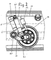
- Fig. 2 shows how the hydropneumatic spring element shown in Fig. 1 used on the wheel suspension of a tracked vehicle can be.
- An impeller 14 is mounted on a rocker 11, the pivotable about a pivot 11.1 on the vehicle housing 12 or on the drive carrier of a otherwise not shown tracked vehicle is arranged.
- the third cylinder 2 of the spring element acc. Fig. 1 is connected via the fastening tab 8.2 with the rocker 11, while the first cylinder 1 via the mounting tab 8.1 with is connected to the vehicle housing.
- a spring element in a stretched construction on this Place would not be installable, but that the existing tight space only with the described with reference to FIG. 1 construction of the spring element allows installation. Is parallel to the spring element
- a hydropneumatic end stop 13 is arranged.
Abstract
Description
Die Erfindung betrifft ein hydropneumatisches Federelement für Fahrzeuge, insbesondere Kettenfahrzeuge, sowie eine Laufradaufhängung an einem Kettenfahrzeug mit einem derartigen Federelement.The invention relates to a hydro-pneumatic spring element for vehicles, in particular tracked vehicles, and an impeller suspension on a tracked vehicle with such a spring element.
Es sind grundsätzlich hydropneumatische Federelemente bekannt,
welche die Merkmale aus dem Oberbegriff des Patentanspruchs 1 aufweisen
und die weiter unten näher erläutert werden. Diese hydropneumatischen
Federelemente sind als gestrecktes System aufgebaut
und besitzen daher eine relativ große Baulänge. There are basically known hydropneumatic spring elements,
which have the features of the preamble of
Es hat sich nun herausgestellt, dass bei Kettenfahrzeugen, insbesondere Kampffahrzeugen mit Kettenlaufwerk, der Einbauraum im Bereich der Laufradaufhängung sehr begrenzt ist und es daher auf große Schwierigkeiten stößt, ein herkömmliches hydropneumatisches Federelement an einer derartigen Laufradaufhängung zu verwenden.It has now been found that in tracked vehicles, in particular Combat vehicles with chain drive, the installation space in the area The suspension is very limited and therefore large Difficulties encountered, a conventional hydropneumatic spring element to use on such an impeller suspension.
Der Erfindung liegt die Aufgabe zugrunde, ein hydropneumatisches
Federelement mit den im Oberbegriff des Patentanspruchs 1 angegebenen
Merkmalen so auszugestalten, dass sein Einbau in einer Laufradaufhängung
an einem Kettenfahrzeug auch bei begrenztem Einbauraum
möglich wird.The invention is based on the object, a hydropneumatic
Spring element with the specified in the preamble of
Weiterhin sollte der Ein- und Ausbau des hydropneumatischen Federelements an einer Laufradaufhängung erleichtert werden.Furthermore, the installation and removal of the hydropneumatic spring element be facilitated on an impeller suspension.
Die Lösung dieser Aufgabe erfolgt erfindungsgemäß mit einem hydropneumatischen
Federelement, das die Merkmale aus dem kennzeichnenden
Teil des Patentanspruchs 1 aufweist. Vorteilhafte Weiterbildungen
der Erfindung sind in den abhängigen Ansprüchen 2 bis 4 beschrieben.
Eine Laufradaufhängung an einem Kettenfahrzeug unter
Verwendung des erfindungsgemäßen, hydropneumatischen Federelements
ist Gegenstand von Patentanspruch 5. Vorteilhafte Weiterbildungen
dieser Laufradaufhängung sind in den Patentansprüchen
6 bis 8 beschrieben.The solution of this object is achieved according to the invention with a hydropneumatic
Spring element that features the characterizing
Part of
Der Grundgedanke der Erfindung besteht darin, ausgehend von dem bekannten hydropneumatischen Federelement in der gestreckten Ausführungsform mit geometrisch hintereinander angeordnetem Federteil und Dämpfungsteil eine Aufteilung vorzusehen, bei welcher Federteil und Dämpfungsteil auf zwei parallel zueinander angeordnete Bauelemente verteilt sind. Hierdurch lässt sich eine beträchtliche Verkürzung der Gesamtbaulänge erreichen, die es nicht nur ermöglicht, das hydropneumatische Federelement nach der Erfindung bei Kettenfahrzeugen mit erheblich eingeschränktem Bauraum im Bereich der Laufradaufhängung einzusetzen, sondern diese Ausbildung ermöglicht auch den Einsatz des Federelements bei einem Kettenfahrzeug mit abgekoppeltem Laufwerk, und sie ermöglicht den Einsatz in Verbindung mit einem hydraulischen Endanschlag. In einer Weiterbildung des erfindungsgemäßen Federelements kann mindestens eine der zur Ankoppelung des Federelements an der Schwinge des Laufwerks bzw. am Fahrzeuggehäuse vorgesehenen Befestigungslaschen mit einem Kopfstück versehen sein, wie dies in Anspruch 4 dargestellt ist, wodurch sich die Montage und Demontage des Federelements unter ungünstigen Platzverhältnissen beträchtlich erleichtert.The basic idea of the invention is, starting from the known hydropneumatic spring element in the extended embodiment with geometrically arranged one behind the other spring part and damping part to provide a division, in which spring part and damping part on two mutually parallel components are distributed. This allows a considerable reduction reach the overall construction length, which not only allows the hydropneumatic spring element according to the invention in tracked vehicles with considerably limited installation space in the area of the wheel suspension but this training also allows the use of the spring element in a tracked vehicle with uncoupled Drive, and it allows use in conjunction with a hydraulic stop. In a further development of the invention Spring element can at least one of the Coupling of the spring element on the rocker of the drive or provided on the vehicle housing mounting tabs with a Be provided head piece, as shown in claim 4, whereby the assembly and disassembly of the spring element under unfavorable space conditions considerably easier.
Im folgenden wird anhand der beigefügten Zeichnungen ein Ausführungsbeispiel für ein hydropneumatisches Federelement nach der Erfindung sowie sein Einsatz an der Laufradaufhängung eines Kettenfahrzeugs näher erläutert.In the following an embodiment will be described with reference to the accompanying drawings for a hydropneumatic spring element according to the invention and its use on the wheel suspension of a tracked vehicle explained in more detail.
In den Zeichnungen zeigen:
Es wird zunächst der prinzipielle Aufbau eines hydropneumatischen Federelements nach dem Stand der Technik erläutert.It is first the basic structure of a hydropneumatic Spring element explained in the prior art.
Bei einem typischen Aufbau eines derartigen bekannten, hydropneumatischen Federelements sind zwei zylindrische Rohrstücke teleskopartig ineinander verschiebbar geführt. In den Rohrstücken sind innerhalb des zylindrischen Raums eine Gaskammer und eine Ölkammer angeordnet, die durch einen in dem zylindrischen Raum abgedichtet und verschiebbar angeordneten Trennkolben voneinander getrennt sind. Die Ölkammer ist über ein im oder am Ende des zylindrischen Raums angeordnetes, hydraulisches Dämpfungsglied mit einer Ölvorratskammer verbunden, deren Innenraum in seiner Länge mittels der teleskopartig ineinander verschiebbar geführten, zylindrischen Rohrstücke veränderbar ist.In a typical construction of such a known, hydropneumatic Spring element are two cylindrical pipe sections telescopically guided into each other. In the pipe sections are within of the cylindrical space a gas chamber and an oil chamber arranged, which is sealed by a in the cylindrical space and slidably disposed separating piston separated from each other are. The oil chamber is over in or at the end of the cylindrical Space arranged, hydraulic damper with an oil reservoir connected, whose interior in its length by means of telescopically guided into one another, cylindrical Pipe pieces is changeable.
Die bekannte Funktionsweise eines derartigen hydropneumatischen Federelements besteht im Prinzip darin, dass beim Einfedern die zylindrischen Rohrstücke ineinandergeschoben werden, wodurch sich der Innenraum der Ölvorratskammer verkleinert und Hydrauliköl von der Ölvorratskammer durch das hydraulische Dämpfungsglied in die Ölkammer einströmt und den Trennkolben in der einen Richtung verschiebt. Die Abfederung geschieht dabei durch Zusammenpressen des in der Gaskammer vorhandenen Gases. Somit kann prinzipiell gesagt werden, dass der die Gaskammer und den Trennkolben enthaltende Bauteilabschnitt die eigentliche Feder darstellt, während der das hydraulische Dämpfungsglied enthaltende Bauteilabschnitt das Dämpfungselement bildet. Beim Ausfedern bewegen sich die zylindrischen Rohrstücke auseinander, wobei sich der Innenraum der Ölvorratskammer vergrößert und Hydrauliköl von der Ölkammer in die Ölvorratskammer durch das hydraulische Dämpfungsglied zurückströmt und sich der Trennkolben unter Ausdehnung des Volumens in der Gaskammer in der anderen Richtung bewegt.The well-known operation of such a hydropneumatic Spring element is in principle that during compression, the cylindrical Pipe pieces are pushed into each other, causing the Interior of the oil reservoir chamber reduced and hydraulic oil from the Oil reservoir through the hydraulic damper in the oil chamber flows in and shifts the separating piston in one direction. The cushioning happens by compressing the gas present in the gas chamber. Thus, in principle can be said be that containing the gas chamber and the separating piston Component section represents the actual spring, while the Hydraulic damping member containing component portion of the damping element forms. When rebounding move the cylindrical Pipe pieces apart, with the interior of the oil reservoir enlarged and hydraulic oil from the oil chamber into the oil reservoir flows back through the hydraulic attenuator and itself the separating piston by expansion of the volume in the gas chamber in the other direction moves.
Üblicherweise besitzt das bekannte hydropneumatische Federelement an seinen beiden Enden jeweils eine mit einem Durchgangsloch versehene Lasche als Ankoppelvorrichtung. Weiterhin sind vorgesehen ein Ein/Ausgang für die Gasfüllung der Gaskammer sowie ein Ein/Ausgang für die Zuführung und Abführung des Hydrauliköls und ggf. die Be/Entlüftung der Ölvorratskammer.Usually, the known hydropneumatic spring element has at its two ends in each case one provided with a through hole Tab as coupling device. Furthermore, a provision is provided Input / output for the gas filling of the gas chamber as well as an input / output for the supply and discharge of the hydraulic oil and possibly the Ventilation of the oil reservoir.
Fig. 1 zeigt nun, wie im Prinzip die Aufteilung der einzelnen Bauelemente des hydropneumatischen Federelements auf zwei parallel zueinander angeordnete Bauteile gedacht ist.Fig. 1 shows how, in principle, the distribution of the individual components of the hydropneumatic spring element on two parallel to each other arranged components is thought.
Das in Fig. 1 dargestellte Federelement ist in der Weise aufgebaut,
dass ein erster Zylinder 1 einen ersten Abschnitt 4 der Ölkammer sowie
das hydraulische Dämpfungsglied 6 und einen Teil der Ölvorratskammer
7 enthält.The spring element shown in Fig. 1 is constructed in the manner
a
In einem zweiten Zylinder 1', der parallel zum ersten Zylinder 1 angeordnet
und als Baueinheit mit ihm verbunden ist, befinden sich ein
zweiter Abschnitt 4' der Ölkammer sowie der Trennkolben 5 und die
Gaskammer 3. In a second cylinder 1 ', which is arranged parallel to the
Die Verbindung dieser beiden parallel zueinander angeordneten Zylinder
1 und 1' erfolgt über ein Verbindungselement 10, das eine hydraulische
Verbindung 10.1 zwischen dem ersten Abschnitt 4 und dem
zweiten Abschnitt 4' der Ölkammer enthält.The connection of these two cylinders arranged parallel to each other
1 and 1 'via a connecting
Ein dritter Zylinder 2, der teleskopartig und abgedichtet im ersten
Zylinder 1 geführt ist, enthält den zweiten Teil der Ölvorratskammer
7. Durch Verschieben der beiden teleskopartig ineinander geführten
Zylinder 1 und 2 ist der Rauminhalt der Ölvorratskammer 7 veränderbar.A
Der erste Zylinder 1 und der zweite Zylinder 1' sind so angeordnet und
miteinander verbunden, dass die über das Verbindungselement 10
miteinander verbundenen Enden im wesentlichen auf gleicher Höhe
liegen. Man erkennt aus Fig. 1, dass sich hierdurch eine erhebliche
Verkürzung der Gesamtbaulänge ergibt, indem die Länge des zweiten
Zylinders 1' kleiner ist als die Gesamtlänge des ersten Zylinders 1 und
des dritten Zylinders 2, und dies gilt für jeden Einfederungszustand
des Federelements.The
Am Verbindungselement 10 ist an der Außenseite eine als Befestigungslasche
8.1 ausgebildete Ankoppelvorrichtung angeordnet, während
am äußeren Ende des dritten Zylinders 2 eine weitere Befestigungslasche
8.2 angeordnet ist. Diese ist so ausgebildet, dass sie aus
zwei Teilen besteht, nämlich einem mit dem dritten Zylinder 2 verbundenen
Basisteil 8.21 und einem mit dem Basisteil über Schraubverbindungen
8.23 verbundenen Kopfstück 8.22. Wie Fig. 1 zu entnehmen,
ist diese Ausbildung so, dass das Durchgangsloch 8.3 der
Befestigungslasche 8.2 in seiner einen Hälfte im Basisstück 8.21 und
mit seiner anderen Hälfte im Kopfstück 8.22 liegt, so dass sich nach
Abnehmen des Kopfstücks 8.22 das Durchgangsloch 8.3 nach außen
öffnet. Dies hat bei der Montage und Demontage den großen Vorteil,
dass das Federelement nicht seitlich auf einen Befestigungsbolzen
aufgesteckt oder von ihm abgezogen werden muss, was bei engem
Bauraum auf beträchtliche Schwierigkeiten stoßen kann, sondern dass
bei abgenommenem Kopfstück 8.22 eine sehr viel leichtere Montage
und Demontage möglich ist.On the connecting
Am zweiten Zylinder 1' ist ein Ein/Ausgang 9.1 für die Gasfüllung der
Gaskammer 3 angeordnet, während am dritten Zylinder 2 ein Ein/Ausgang
9.2 für die Ölfüllung angeordnet ist. Letzterer kann auch am ersten
Zylinder 1 angeordnet sein.On the second cylinder 1 'is an input / output 9.1 for the gas filling of
Gas chamber 3 arranged, while the
Fig. 2 zeigt, wie das in Fig. 1 dargestellte hydropneumatische Federelement
an der Laufradaufhängung eines Kettenfahrzeugs eingesetzt
werden kann. Ein Laufrad 14 ist an einer Schwinge 11 gelagert, die
über ein Drehgelenk 11.1 schwenkbar am Fahrzeuggehäuse 12 bzw.
am Laufwerkträger eines im übrigen nicht dargestellten Kettenfahrzeugs
angeordnet ist. Der dritte Zylinder 2 des Federelements gem.
Fig. 1 ist über die Befestigungslasche 8.2 mit der Schwinge 11 verbunden,
während der erste Zylinder 1 über die Befestigungslasche 8.1 mit
dem Fahrzeuggehäuse verbunden ist. Es ist der Fig. 2 ohne weiteres zu
entnehmen, dass ein Federelement in gestreckter Bauweise an dieser
Stelle nicht einbaubar wäre, sondern dass der vorhandene enge Bauraum
nur mit der anhand von Fig. 1 geschilderten Bauweise des Federelements
einen Einbau ermöglicht. Parallel zum Federelement ist
außerdem ein hydropneumatischer Endanschlag 13 angeordnet.Fig. 2 shows how the hydropneumatic spring element shown in Fig. 1
used on the wheel suspension of a tracked vehicle
can be. An
Claims (8)
Applications Claiming Priority (2)
| Application Number | Priority Date | Filing Date | Title |
|---|---|---|---|
| DE102004013768 | 2004-03-20 | ||
| DE200410013768 DE102004013768A1 (en) | 2004-03-20 | 2004-03-20 | Hydropneumatic spring element for vehicles, in particular tracked vehicles, as well as wheel suspension on a tracked vehicle with such a spring element |
Publications (2)
| Publication Number | Publication Date |
|---|---|
| EP1577580A2 true EP1577580A2 (en) | 2005-09-21 |
| EP1577580A3 EP1577580A3 (en) | 2006-05-31 |
Family
ID=34833213
Family Applications (1)
| Application Number | Title | Priority Date | Filing Date |
|---|---|---|---|
| EP05003352A Withdrawn EP1577580A3 (en) | 2004-03-20 | 2005-02-17 | Hydropneumatic spring for vehicle, especially tracked vehicle, and suspension unit for roll wheel on a tracked vehicle equipped with this spring |
Country Status (2)
| Country | Link |
|---|---|
| EP (1) | EP1577580A3 (en) |
| DE (1) | DE102004013768A1 (en) |
Cited By (3)
| Publication number | Priority date | Publication date | Assignee | Title |
|---|---|---|---|---|
| WO2009065955A1 (en) | 2007-11-23 | 2009-05-28 | Strömsholmen Ab | Suspension system, vehicle comprising such a suspension system and a method for controlling a suspension system |
| FR2988453A1 (en) * | 2012-03-22 | 2013-09-27 | Peugeot Citroen Automobiles Sa | Hydraulic shock absorber for use in car, has offset compensating chamber that comprises remote trigger stop that is utilized for slowing down floating piston when shock absorber arrives in relaxation position |
| CN108343699A (en) * | 2018-05-01 | 2018-07-31 | 宋金博 | A kind of flexible shock absorber of the fluid pressure type that can reduce rail transit noise |
Families Citing this family (1)
| Publication number | Priority date | Publication date | Assignee | Title |
|---|---|---|---|---|
| DE102006010262A1 (en) * | 2006-03-02 | 2007-09-13 | Gisela Weber | Mounting kit for a tail lift |
Family Cites Families (11)
| Publication number | Priority date | Publication date | Assignee | Title |
|---|---|---|---|---|
| GB942804A (en) * | 1959-03-31 | 1963-11-27 | Svenska Aeroplan Ab | A combined springing and shock absorbing device |
| US3077345A (en) * | 1960-03-29 | 1963-02-12 | Svenska Aeroplan Ab | Air-oil shock absorber especially adapted for ground vehicles |
| DE1802193A1 (en) * | 1968-10-10 | 1970-08-27 | Auto Teile Praez Kg | Hydro-pneumatic gas spring, in particular for supporting and adjusting hospital beds or the like. |
| DE2446643A1 (en) * | 1974-09-30 | 1976-04-08 | Yamaha Motor Co Ltd | Motorcycle rear suspension unit - has hydro-pneumatic and spring strut with cooling reservoir for fluid |
| US4153237A (en) * | 1976-11-01 | 1979-05-08 | Supalla Steven A | Hydrapneumatic suspension unit and valving structure |
| US4159106A (en) * | 1977-11-10 | 1979-06-26 | Nyman Bengt E | Vehicular suspension unit |
| DE2855561A1 (en) * | 1978-12-22 | 1980-07-10 | Fichtel & Sachs Ag | SHOCK ABSORBER OR SHOCK ABSORBER FOR VEHICLES WITH PRESSURE STOP |
| US4641854A (en) * | 1984-07-25 | 1987-02-10 | Honda Giken Kogyo Kabushiki Kaisha | Wheel suspension for a vehicle |
| US4872537A (en) * | 1988-06-06 | 1989-10-10 | Brian Warner | Adjustable damper means for shock absorber |
| GB2321687A (en) * | 1997-01-30 | 1998-08-05 | Pilot Precision Dampers Ltd | Damper |
| FR2769261B1 (en) * | 1997-10-08 | 2003-10-03 | Giat Ind Sa | IMPROVEMENT ON A PULL ARM SUSPENSION SYSTEM FOR A DRIVING REAR WHEEL OF A MOTOR VEHICLE |
-
2004
- 2004-03-20 DE DE200410013768 patent/DE102004013768A1/en not_active Withdrawn
-
2005
- 2005-02-17 EP EP05003352A patent/EP1577580A3/en not_active Withdrawn
Non-Patent Citations (1)
| Title |
|---|
| None |
Cited By (4)
| Publication number | Priority date | Publication date | Assignee | Title |
|---|---|---|---|---|
| WO2009065955A1 (en) | 2007-11-23 | 2009-05-28 | Strömsholmen Ab | Suspension system, vehicle comprising such a suspension system and a method for controlling a suspension system |
| US7823895B2 (en) | 2007-11-23 | 2010-11-02 | Stromsholmen Ab | Suspension system, vehicle comprising such a suspension system and a method for controlling a suspension system |
| FR2988453A1 (en) * | 2012-03-22 | 2013-09-27 | Peugeot Citroen Automobiles Sa | Hydraulic shock absorber for use in car, has offset compensating chamber that comprises remote trigger stop that is utilized for slowing down floating piston when shock absorber arrives in relaxation position |
| CN108343699A (en) * | 2018-05-01 | 2018-07-31 | 宋金博 | A kind of flexible shock absorber of the fluid pressure type that can reduce rail transit noise |
Also Published As
| Publication number | Publication date |
|---|---|
| EP1577580A3 (en) | 2006-05-31 |
| DE102004013768A1 (en) | 2005-10-20 |
Similar Documents
| Publication | Publication Date | Title |
|---|---|---|
| DE2320913A1 (en) | HYDRAULIC SHOCK ABSORBER | |
| DE19604558C1 (en) | Piston-cylinder unit with connecting rod axially movable in cylinder | |
| EP1586789A1 (en) | Elastic support for a driver's cab | |
| EP1270987A2 (en) | Bush shaped support for an aggregate | |
| DE102018210403A1 (en) | Vehicle wheel suspension with an adjustment system for the base point of a body suspension spring | |
| DE102014105624A1 (en) | Spring drive for a closure element of a motor vehicle | |
| EP1577580A2 (en) | Hydropneumatic spring for vehicle, especially tracked vehicle, and suspension unit for roll wheel on a tracked vehicle equipped with this spring | |
| DE102009039841A1 (en) | Spring damper element for a cab suspension | |
| DE102004034632A1 (en) | Elastomer bush bearing with axial stop | |
| DE7828716U1 (en) | DEVICE FOR MUFFLING POWER STEERING | |
| EP0810928B1 (en) | Height-regulated hydropneumatic suspension | |
| EP1694982A1 (en) | Switchable hydraulically damping bush bearing | |
| DE102009058760A1 (en) | Air inlet device for use in cooling device of motor vehicle, comprises modification unit for modification of its free opening by longitudinal positioning element arranged in free opening | |
| EP3381721B1 (en) | Suspension system | |
| WO2017137180A1 (en) | Vibration damper having a compensation chamber | |
| DE3230936A1 (en) | Spring and damping device for the wheel suspension of vehicles | |
| DE2141366A1 (en) | Tool for assembling or disassembling coil spring shock absorbers and procedures using this tool | |
| DE10104661B4 (en) | Suspension device for loads moving in the vertical direction, in particular pipes and the like | |
| DE102017216662A1 (en) | Damping arrangement for a vibration damper of a motor vehicle | |
| DE102018119086B4 (en) | strut and vehicle | |
| DE10044182A1 (en) | Adjusting device to connect stabilizer to motor vehicle body has cylinder and piston rod with fastening eyes for eccentric cylinder fastening | |
| DE10026970B4 (en) | Elastomer spring and shock absorber arrangement with such an elastomeric spring | |
| EP0114623A1 (en) | Hydraulic telescopic shock absorber for a motor vehicle, in particular for a motorcycle | |
| DE102015119731A1 (en) | damper device | |
| DE102006012002A1 (en) | Air spring used in motor vehicles comprises a pot with a main part and a secondary part connected together by an expanding bellows |
Legal Events
| Date | Code | Title | Description |
|---|---|---|---|
| PUAI | Public reference made under article 153(3) epc to a published international application that has entered the european phase |
Free format text: ORIGINAL CODE: 0009012 |
|
| AK | Designated contracting states |
Kind code of ref document: A2 Designated state(s): AT BE BG CH CY CZ DE DK EE ES FI FR GB GR HU IE IS IT LI LT LU MC NL PL PT RO SE SI SK TR |
|
| AX | Request for extension of the european patent |
Extension state: AL BA HR LV MK YU |
|
| PUAL | Search report despatched |
Free format text: ORIGINAL CODE: 0009013 |
|
| AK | Designated contracting states |
Kind code of ref document: A3 Designated state(s): AT BE BG CH CY CZ DE DK EE ES FI FR GB GR HU IE IS IT LI LT LU MC NL PL PT RO SE SI SK TR |
|
| AX | Request for extension of the european patent |
Extension state: AL BA HR LV MK YU |
|
| AKX | Designation fees paid | ||
| STAA | Information on the status of an ep patent application or granted ep patent |
Free format text: STATUS: THE APPLICATION IS DEEMED TO BE WITHDRAWN |
|
| 18D | Application deemed to be withdrawn |
Effective date: 20061201 |
|
| REG | Reference to a national code |
Ref country code: DE Ref legal event code: 8566 |