EP1577503A1 - Strömungsmaschine, Leitgitter und Montagering hierfür - Google Patents
Strömungsmaschine, Leitgitter und Montagering hierfür Download PDFInfo
- Publication number
- EP1577503A1 EP1577503A1 EP04005483A EP04005483A EP1577503A1 EP 1577503 A1 EP1577503 A1 EP 1577503A1 EP 04005483 A EP04005483 A EP 04005483A EP 04005483 A EP04005483 A EP 04005483A EP 1577503 A1 EP1577503 A1 EP 1577503A1
- Authority
- EP
- European Patent Office
- Prior art keywords
- ring
- surface portion
- blade
- blades
- rings
- Prior art date
- Legal status (The legal status is an assumption and is not a legal conclusion. Google has not performed a legal analysis and makes no representation as to the accuracy of the status listed.)
- Granted
Links
- 239000012530 fluid Substances 0.000 claims description 7
- 230000002093 peripheral effect Effects 0.000 claims description 7
- 239000007789 gas Substances 0.000 description 6
- 238000010276 construction Methods 0.000 description 2
- 238000007373 indentation Methods 0.000 description 2
- 208000016285 Movement disease Diseases 0.000 description 1
- 230000015572 biosynthetic process Effects 0.000 description 1
- 238000002485 combustion reaction Methods 0.000 description 1
- 230000002349 favourable effect Effects 0.000 description 1
- 238000004519 manufacturing process Methods 0.000 description 1
- 239000000463 material Substances 0.000 description 1
- 238000003801 milling Methods 0.000 description 1
- 125000006850 spacer group Chemical group 0.000 description 1
Images


Classifications
-
- F—MECHANICAL ENGINEERING; LIGHTING; HEATING; WEAPONS; BLASTING
- F02—COMBUSTION ENGINES; HOT-GAS OR COMBUSTION-PRODUCT ENGINE PLANTS
- F02C—GAS-TURBINE PLANTS; AIR INTAKES FOR JET-PROPULSION PLANTS; CONTROLLING FUEL SUPPLY IN AIR-BREATHING JET-PROPULSION PLANTS
- F02C6/00—Plural gas-turbine plants; Combinations of gas-turbine plants with other apparatus; Adaptations of gas-turbine plants for special use
- F02C6/04—Gas-turbine plants providing heated or pressurised working fluid for other apparatus, e.g. without mechanical power output
- F02C6/10—Gas-turbine plants providing heated or pressurised working fluid for other apparatus, e.g. without mechanical power output supplying working fluid to a user, e.g. a chemical process, which returns working fluid to a turbine of the plant
- F02C6/12—Turbochargers, i.e. plants for augmenting mechanical power output of internal-combustion piston engines by increase of charge pressure
-
- F—MECHANICAL ENGINEERING; LIGHTING; HEATING; WEAPONS; BLASTING
- F01—MACHINES OR ENGINES IN GENERAL; ENGINE PLANTS IN GENERAL; STEAM ENGINES
- F01D—NON-POSITIVE DISPLACEMENT MACHINES OR ENGINES, e.g. STEAM TURBINES
- F01D17/00—Regulating or controlling by varying flow
- F01D17/10—Final actuators
- F01D17/12—Final actuators arranged in stator parts
- F01D17/14—Final actuators arranged in stator parts varying effective cross-sectional area of nozzles or guide conduits
- F01D17/16—Final actuators arranged in stator parts varying effective cross-sectional area of nozzles or guide conduits by means of nozzle vanes
- F01D17/165—Final actuators arranged in stator parts varying effective cross-sectional area of nozzles or guide conduits by means of nozzle vanes for radial flow, i.e. the vanes turning around axes which are essentially parallel to the rotor centre line
Definitions
- the invention relates to a turbomachine, in particular a turbocharger, with a turbine housing having at least one supply channel for a drive fluid, such as Exhaust gas, in which at least one turbine rotor is rotatably mounted, and the fluid or Exhaust gas via a the turbine rotor radially outer surrounding Leitgitter variable turbine geometry can be fed.
- the guide grid has a blade bearing ring, on each of which on an associated axle or shaft a variety of about its axis inside a range of motion adjustable blades in a limited blade space is mounted around the turbine rotor, the fluid or exhaust gas so on the blades in adjustable amount can be fed.
- the blade bearing ring forms the one axial limit a scoop room.
- the blade bearing ring forms another, the blade bearing ring axially opposite ring the other axial boundary of the blade space, but it is also possible, the blade bearing ring a wall of the turbine housing to face.
- This axially opposite ring may optionally have a Form part of the Leitgitters and serve the assembly in the turbine housing.
- the invention also relates to a guide grid and to a mounting ring.
- turbocharger of this kind is already in the older, not previously published patent application EP 02 018 296.0. This involves the integral formation of spacer studs on the ring, which are arranged in this receding peripheral region should be.
- turbomachines such as turbochargers
- turbochargers have to function without complaint at all temperatures.
- the high, temperatures appearing at full operation lead to thermal expansion of the individual Components, of course, these dimensional changes are particularly uncomfortable affect moving parts, which may be due to thermal expansion and / or deposits are hindered in their mobility or only with significantly increased Force are to move.
- the requirements for the permissible Tolerances are relatively high, especially in the area of the guide grid. All this concerns in particular, the guide vanes which can be moved in the case of a variable geometry guide vanes.
- the invention is therefore based on the object, a turbomachine of the beginning Such a type or a guide grid and / or a blade bearing ring such form, that even with tolerable tolerances held within tolerable limits a movement disorder to prevent the vanes.
- the solution of this problem is achieved in that at least one of Rings, in particular at least the blade bearing ring, and / or the respective one of Ring-facing side surface of the blades one in the axial direction of the blade space have receding surface portion, wherein in the case of a ring of the axial receding surface section extends into the range of movement of the blades.
- this solution is initially because of the axially receding Surface section apparently created a greater, rather than a lower tolerance becomes. But this is not so because this area section only a section, ie a subarea is. In the case of a ring, this is preferably at the peripheral edge - up to the range of movement of the blades - and in the case of a blade only in Area to the side of their free end, where the tolerance requirements allow. in the Trap of the ring, this leads to a narrowing flow channel, which is more likely creates better flow conditions.
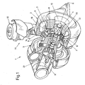
- a turbocharger 1 in a conventional manner a turbine housing part 2 and an associated compressor housing part 3 along an axis of rotation R are arranged.
- the turbine housing part 2 is partially shown in section, so that a blade bearing ring 6 forming a radially outer guide grid, distributed over the circumference Guide vanes 7 about their the blade bearing ring 6 passing through pivot axes.
- the mentioned pivot axes 8 can as waves for transmitting the movement of the adjusting ring 5 on the Blades 7 may be formed; but they can also only represent stub axles, when the blades 7 are guided at one of their free ends, as in US-A-64,19,464 is described.
- an actuating device 11 To control the movement or the position of the guide vanes 7 is an actuating device 11 provided. This can be of any nature in itself, but it is preferable if, in a conventional manner, it has a control housing 12 that controls the movement a ram member 14 attached to it controls its movement in known manner on a behind the blade bearing ring 6 (left behind in Fig. 1) the same adjusting ring 5 implement the same in a slight rotational movement.
- This rotational movement are about the shafts 8
- the vanes 7 in terms of their Rotary position relative to the turbine rotor 4 adjusted so that they are from an approximately tangential an extreme position in an approximately radially extending other extreme position adjustable are.
- the exhaust gas supplied via the supply channel of an internal combustion engine more or less supplied to the turbine rotor 4, before it at the along the axis of rotation R extending axial neck 10 exits again.
- this blade space 13 may not be much larger than the width of the blades 7, because then the exhaust energy would suffer leakage.
- the Bucket 13 but also not be too tight, because then the blades 7 could jam. This is also particularly important because yes through the hot Exhaust gases must be expected with a certain thermal expansion of the material. These Thermal expansion is problematic insofar as to avoid flow losses the tolerances must be kept very small, on the other hand, the construction in the different temperatures must work without complaint. There is a difficulty this is that not the blades 7 of the guide grid 5-8 hindered in their mobility become.
- the in Fig. 2 schematically shown part of a mounting ring 16 at least along its Peripheral edge of a receding in the axial direction of the blade chamber 13 surface 19a.
- This area deviates from that of the blades 7 (not shown in FIG. 2).
- facing surface of the mounting ring 16 at a uniform angle ⁇ back which in this range of movement of the blades (as with reference to FIGS. 5 and 6 is shown) created a larger clearance for the radially outer blade ends becomes. Therefore, the outer ends of the blades 7 - even in the case of a certain Play their axes 8 (see Fig. 1) within the blade bearing ring, either by tolerance error, be it by some wear and tear - not by this receding Surface 19a strip and thus be hampered in their movement.
- the receding surface 19 may take various forms, for example it does not need to be beveled at a uniform angle ⁇ , but rather the Angle in the radial direction of the ring 6 also vary.
- Fig. 3 shows an embodiment with a gradually receding surface 19b with a circumferential step 17.
- the receding surface is on one of the rings and in particular formed on the mounting ring 16.
- the receding surface 19c may also be provided on the sides of the blades 7, i. the area 19c deviates from the neighboring one Ring back so that the blade 7 in the region of its radially outer end 7a narrower than in the middle and its surface in plan view a bevel around the angle ⁇ 1.
- This bevel is shown in Fig. 4 only on one side, but can also be provided on both sides.
- FIGS. 5 and 6 illustrate the situation with respect to the mounting plate 16 adjustable blades 7 in the open state (Fig. 5) and in the closed state (Fig. 6). It can be seen that the respective radially outer end 7a of each blade 7 is located moved over an area that you through the receding surface 19 (be it now angled as the surface 19a in Fig. 2 or stepped as the surface 19b in Fig. 3) a good mobility even with slight inclination of its shaft 8 in the bearing of the blade bearing ring (6 in Fig. 1) secures. It can be seen from Figs. 5 and 6 also that in this construction the radially outer end 7a a relatively greater distance from the geometric Axis 8 has as the radially inner end 7b. Therefore, a possible deflection by a bearing clearance of the shaft 8 in the blade bearing ring 6 on the side 7 a and the largest be.
- the present invention is not limited to this form, but would be it is also possible, on the side of the radially inner end 7b, a receding surface although this will generally be less preferred. Because the radial External recession of the surface 19 namely results in addition to a certain flow concentration and thus favorable flow conditions. On the other hand it is to Avoidance of acting on the axis or shaft 8 shear forces advantageous if at least the surface 19 in the areas of the blade axes 8 without axial backward movement is formed, as shown in Figs. 5 and 6 also shown.
- turbocharger 2 Turbine casing 3
- Compressor housing part Compressor housing part 4
- turbine rotor 5 adjusting 6
- Nozzle ring 7 shovel 8th Axles, waves v. 7 9 supply channel 10
- Support 11 actuator 12
- Control housing v. 11 blade space 14
- Plunger link v.11 15 ring-shaped part v. 2
- Mounting ring od 17 peripheral step 18
- mounting holes 19 receding surface 20 indentation 21 compressor rotor
Landscapes
- Engineering & Computer Science (AREA)
- Chemical & Material Sciences (AREA)
- Mechanical Engineering (AREA)
- General Engineering & Computer Science (AREA)
- Chemical Kinetics & Catalysis (AREA)
- General Chemical & Material Sciences (AREA)
- Combustion & Propulsion (AREA)
- Supercharger (AREA)
Abstract
Description
- Fig. 1
- einen Turbolader in Perspektivansicht, teilweise im Schnitt, an dem die vorliegende Erfindung zur Anwendung kommt; und
- Fig. 2
- eine Perspektivansicht eines Teils eines ersten erfindungsgemäßen Ausführungsbeispieles eines in einen Turbolader nach Fig. 1 einzusetzenden Schaufellagerringes ohne die Bohrungen für die Achsen der Leitschaufeln;
- Fig. 3
- eine Perspektivansicht eines Teils eines ersten erfindungsgemäßen Ausführungsbeispieles eines in einen Turbolader nach Fig. 1 einzusetzenden Schaufellagerringes ohne die Bohrungen für die Achsen der Leitschaufeln;
- Fig. 4
- eine Perspektivansicht einer in einen Turbolader nach Fig. 1 wahlweise einzusetzenden Schaufel; und die
- Fig. 5
- und 6 eine Seitenansicht auf einen Schaufellagerring mit den Schaufeln in geöffneter und geschlossener Stellung der Schaufeln.
| 1 | Turbolader | 2 | Turbinengehäuseteil |
| 3 | Kompressorgehäuseteil | 4 | Turbinenrotor |
| 5 | Verstellring | 6 | Schaufellagerring |
| 7 | Schaufeln | 8 | Achsen, Wellen v. 7 |
| 9 | Zufuhrkanal | 10 | Stutzen |
| 11 | Betätigungseinrichtung | 12 | Steuergehäuse v. 11 |
| 13 | Schaufelraum | 14 | Stößelglied v.11 |
| 15 | ringförmiger Teil v. 2 | 16 | Montagering od. -scheibe |
| 17 | Umfangsstufe | 18 | Befestigungslöcher |
| 19 | zurückweichende Fläche | 20 | Einbuchtung |
| 21 | Kompressorrotor |
Claims (9)
- Strömungsmaschine, insbesondere Turbolader, die folgendes aufweist:dadurch gekennzeichnet, daßein Turbinengehäuse (2) mit mindestens einem Zufuhrkanal (9) für ein Antriebsfluid, wie Abgas, in demmindestens ein Turbinenrotor (4) drehbar gelagert ist, und dem das Fluid bzw. Abgas überein den Turbinenrotor (4) radial außen umgebendes Leitgitter variabler Turbinengeometrie zuführbar ist, welches Leitgittereinen Schaufellagerring (6) aufweist, an dem jeweils an einer zugehörigen Achse oder Welle (8) eine Vielzahl von um ihre Achse (8) innerhalb eines Bewegungsbereiches verstellbaren Schaufeln (7) in einem begrenzten Schaufelraum (13) rund um den Turbinenrotor (4) gelagert ist, dem Fluid bzw. Abgas so über die Schaufeln (7) in einstellbarer Menge zuführbar ist, welcher Schaufellagerring (6) die eine axiale Begrenzung eines Schaufelraumes (13) bildet, und gegebenenfalls miteinem weiteren, dem Schaufellagerring (6) axial gegenüberliegenden Ring (16), der die andere axiale Begrenzung des Schaufelraumes (13) bildet,
mindestens einer der Ringe (6, 16), insbesondere wenigstens der Montagering (16), und/oder die jeweilige wenigstens einem der Ringe (6, 16) zugekehrte Seitenfläche der Schaufeln (7) einen in axialer Richtung vom Schaufelraum (13) zurückweichende Flächenabschnitt (19) aufweisen, wobei im Falle eines Ringes (6, 16) der axial zurückweichende Flächenabschnitt (19) bis in den Bewegungsbereich der Schaufeln (7) reicht. - Strömungsmaschine nach Anspruch 1, dadurch gekennzeichnet, daß wenigstens eines der folgenden Merkmale vorgesehen ist:a) der Flächenabschnitt (19a) weicht schräg unter einem Winkel (β, β1) zurück;b) der Flächenabschnitt (19b) weicht unter Bildung einer Stufe (17) zurück;c) der Flächenabschnitt (19a, 19b) ist am äußeren Umfangsrand wenigstens eines der Ringe (6), insbesondere des Montageringes (16), vorgesehen.
- Strömungsmaschine nach Anspruch 1 oder 2, dadurch gekennzeichnet, der Flächenabschnitt im Bereiche der Schaufelachsen (8) ohne axiale Zurückweichung ausgebildet ist.
- Leitgitter variabler Turbinengeometrie für eine Strömungsmaschine nach einem der vorhergehenden Ansprüche, welches einen Schaufellagerring (6) aufweist, an dem jeweils an einer zugehörigen Achse oder Welle (8) eine Vielzahl von um ihre Achse (8) innerhalb eines Bewegungsbereiches verstellbaren Schaufeln (7) in einem begrenzten Schaufelraum (13) rund um den Turbinenrotor (4) gelagert ist, dem Fluid bzw. Abgas so über die Schaufeln (7) in einstellbarer Menge zuführbar ist, welcher Schaufellagerring (6) die eine axiale Begrenzung eines Schaufelraumes (13) bildet, und gegebenenfalls mit einem weiteren, dem Schaufellagerring (6) axial gegenüberliegenden Ring (16), der die andere axiale Begrenzung des Schaufelraumes (13) bildet,
dadurch gekennzeichnet, daß
mindestens einer der Ringe (6, 16), insbesondere wenigstens der Montagering (16), und/oder die jeweilige wenigstens einem der Ringe (6, 16) zugekehrte Seitenfläche der Schaufeln (7) einen in axialer Richtung vom Schaufelraum (13) zurückweichende Flächenabschnitt (19) aufweisen, wobei im Falle eines Ringes (6, 16) der axial zurückweichende Flächenabschnitt (19) bis in den Bewegungsbereich der Schaufeln (7) reicht. - Leitgitter nach Anspruch 4, dadurch gekennzeichnet, daß wenigstens eines der folgenden Merkmale vorgesehen ist:a) der Flächenabschnitt (19a) weicht schräg unter einem Winkel (β, β1) zurück;b) der Flächenabschnitt (19b) weicht unter Bildung einer Stufe (17) zurück;c) der Flächenabschnitt (19a, 19b) ist am äußeren Umfangsrand wenigstens eines der Ringe (6), insbesondere des Montageringes (16), vorgesehen.
- Leitgitter nach Anspruch 4 oder 5, dadurch gekennzeichnet, daß der jeweilige Ring (6, 16) im Bereiche der Schaufelachsen (8) ohne axiale Zurückweichung ausgebildet ist.
- Montagering (16) für einen Turbolader nach einem der Ansprüche 1-3 bzw. für ein Leitgitter nach einem der Ansprüche 4 bis 6, dadurch gekennzeichnet, daß er, vorzugsweise mindestens entlang seines Umfangsrandes, einen in axialer Richtung vom Schaufelraum (13) zurückweichenden, bevorzugt bis mindestens in den radial äußeren Teil des Bewegungsbereiches der Schaufeln (7) reichenden, Flächenabschnitt (19) aufweist.
- Montagering nach Anspruch 7, dadurch gekennzeichnet, daß der Flächenabschnitt (19a) schräg unter einem Winkel (β, β1) zurückweicht und/oder
daß der Flächenabschnitt (19b) unter Bildung einer Stufe (17) zurückweicht. - Montagering nach Anspruch 7 oder 8, dadurch gekennzeichnet, daß er (16) im Bereiche der Schaufelachsen (8) ohne axiale Zurückweichung ausgebildet ist.
Priority Applications (2)
| Application Number | Priority Date | Filing Date | Title |
|---|---|---|---|
| EP20040005483 EP1577503B1 (de) | 2004-03-08 | 2004-03-08 | Strömungsmaschine, Leitgitter und Montagering hierfür |
| DE200450000984 DE502004000984D1 (de) | 2004-03-08 | 2004-03-08 | Strömungsmaschine, Leitgitter und Montagering hierfür |
Applications Claiming Priority (1)
| Application Number | Priority Date | Filing Date | Title |
|---|---|---|---|
| EP20040005483 EP1577503B1 (de) | 2004-03-08 | 2004-03-08 | Strömungsmaschine, Leitgitter und Montagering hierfür |
Publications (2)
| Publication Number | Publication Date |
|---|---|
| EP1577503A1 true EP1577503A1 (de) | 2005-09-21 |
| EP1577503B1 EP1577503B1 (de) | 2006-07-19 |
Family
ID=34833588
Family Applications (1)
| Application Number | Title | Priority Date | Filing Date |
|---|---|---|---|
| EP20040005483 Expired - Lifetime EP1577503B1 (de) | 2004-03-08 | 2004-03-08 | Strömungsmaschine, Leitgitter und Montagering hierfür |
Country Status (2)
| Country | Link |
|---|---|
| EP (1) | EP1577503B1 (de) |
| DE (1) | DE502004000984D1 (de) |
Cited By (3)
| Publication number | Priority date | Publication date | Assignee | Title |
|---|---|---|---|---|
| WO2007118663A1 (de) * | 2006-04-11 | 2007-10-25 | Borgwarner Inc. | Turbolader |
| US10190488B2 (en) | 2015-01-22 | 2019-01-29 | Bosch Mahle Turbo Systems Gmbh & Co. Kg | Method for producing a variable turbine geometry |
| CN119538778A (zh) * | 2024-11-08 | 2025-02-28 | 西安交通大学 | 基于深度学习的涡轮温度分布预测方法 |
Families Citing this family (3)
| Publication number | Priority date | Publication date | Assignee | Title |
|---|---|---|---|---|
| DE102011075285A1 (de) | 2011-05-05 | 2012-11-08 | Bosch Mahle Turbo Systems Gmbh & Co. Kg | Ladeeinrichtung |
| DE102011077135A1 (de) | 2011-06-07 | 2012-12-13 | Bosch Mahle Turbo Systems Gmbh & Co. Kg | Variable Turbinen-/Verdichtergeometrie |
| DE102015216306A1 (de) | 2015-08-26 | 2017-03-02 | Bosch Mahle Turbo Systems Gmbh & Co. Kg | Leitschaufel für eine variable Turbinengeometrie, Verfahren zur Herstellung einer Leitschaufel und Turbolader mit einer Leitschaufel |
Citations (4)
| Publication number | Priority date | Publication date | Assignee | Title |
|---|---|---|---|---|
| EP0226444A2 (de) * | 1985-12-11 | 1987-06-24 | AlliedSignal Inc. | Turbolader mit verstellbaren Leitschaufeln |
| US4804316A (en) * | 1985-12-11 | 1989-02-14 | Allied-Signal Inc. | Suspension for the pivoting vane actuation mechanism of a variable nozzle turbocharger |
| EP1357255A1 (de) * | 2002-04-26 | 2003-10-29 | BorgWarner Inc. | Turbokompressor mit verstellbaren Leitschaufeln |
| EP1394364A1 (de) * | 2002-08-26 | 2004-03-03 | BorgWarner Inc. | Turbolader und Schaufellagerring hierfür |
-
2004
- 2004-03-08 EP EP20040005483 patent/EP1577503B1/de not_active Expired - Lifetime
- 2004-03-08 DE DE200450000984 patent/DE502004000984D1/de not_active Expired - Lifetime
Patent Citations (4)
| Publication number | Priority date | Publication date | Assignee | Title |
|---|---|---|---|---|
| EP0226444A2 (de) * | 1985-12-11 | 1987-06-24 | AlliedSignal Inc. | Turbolader mit verstellbaren Leitschaufeln |
| US4804316A (en) * | 1985-12-11 | 1989-02-14 | Allied-Signal Inc. | Suspension for the pivoting vane actuation mechanism of a variable nozzle turbocharger |
| EP1357255A1 (de) * | 2002-04-26 | 2003-10-29 | BorgWarner Inc. | Turbokompressor mit verstellbaren Leitschaufeln |
| EP1394364A1 (de) * | 2002-08-26 | 2004-03-03 | BorgWarner Inc. | Turbolader und Schaufellagerring hierfür |
Cited By (3)
| Publication number | Priority date | Publication date | Assignee | Title |
|---|---|---|---|---|
| WO2007118663A1 (de) * | 2006-04-11 | 2007-10-25 | Borgwarner Inc. | Turbolader |
| US10190488B2 (en) | 2015-01-22 | 2019-01-29 | Bosch Mahle Turbo Systems Gmbh & Co. Kg | Method for producing a variable turbine geometry |
| CN119538778A (zh) * | 2024-11-08 | 2025-02-28 | 西安交通大学 | 基于深度学习的涡轮温度分布预测方法 |
Also Published As
| Publication number | Publication date |
|---|---|
| DE502004000984D1 (de) | 2006-08-31 |
| EP1577503B1 (de) | 2006-07-19 |
Similar Documents
| Publication | Publication Date | Title |
|---|---|---|
| EP1536103B1 (de) | Strömungsmaschine mit Leitgitter und Befestigungseinrichtung dafür | |
| DE69828255T2 (de) | Dichtungsstruktur für gasturbinen | |
| DE3226052C2 (de) | Spaltdichtung für axial durchströmte Gasturbinen | |
| EP2078136B1 (de) | Reibgeschweisste turboladerwelle und herstellungsverfahren dafür | |
| DE60212760T2 (de) | Turbine mit variabler Einlassgeometrie | |
| EP3283733B1 (de) | Leitschaufelverstellvorrichtung und strömungsmaschine | |
| EP2132414B1 (de) | Shiplap-anordnung | |
| EP2960438A1 (de) | Leitschaufelvorrichtung für eine gasturbine sowie gasturbine mit einer solchen leitschaufelvorrichtung | |
| WO2004018844A1 (de) | Rezirkulationsstruktur für turboverdichter | |
| DE3618331A1 (de) | Betaetigungshebel fuer ein paar verstellbare leitschaufeln | |
| EP1394364A1 (de) | Turbolader und Schaufellagerring hierfür | |
| CH701814B1 (de) | Laufschaufelanordnung für eine Turbine. | |
| DE4214775A1 (de) | Dampfturbine mit einem Drehschieber | |
| DE10330084A1 (de) | Rezirkulationsstruktur für Turboverdichter | |
| WO2020120254A1 (de) | Abgasturbine mit variabler geometrie für einen abgasturbolader | |
| EP1564380A1 (de) | Turbineneinheit sowie Leitgitter und Verstellring hierfür | |
| EP2140111B1 (de) | Strömungsmaschine | |
| DE3145783A1 (de) | Verbrennungsmotor | |
| DE60305011T2 (de) | Verbesserte schaufelausführung zur verwendung in turboladern mit variabler geometrie | |
| DE112010004596T5 (de) | Turbolade | |
| DE112020005428B4 (de) | Variable Düsenvorrichtung, Turbine und Turbolader | |
| EP1577503B1 (de) | Strömungsmaschine, Leitgitter und Montagering hierfür | |
| EP3312388B1 (de) | Rotorteil, zugehörigeverdichter, turbine und herstellungsverfahren | |
| CH624293A5 (de) | ||
| DE102012212483B4 (de) | Zahnärztliches Präparationsinstrument |
Legal Events
| Date | Code | Title | Description |
|---|---|---|---|
| PUAI | Public reference made under article 153(3) epc to a published international application that has entered the european phase |
Free format text: ORIGINAL CODE: 0009012 |
|
| AK | Designated contracting states |
Kind code of ref document: A1 Designated state(s): AT BE BG CH CY CZ DE DK EE ES FI FR GB GR HU IE IT LI LU MC NL PL PT RO SE SI SK TR |
|
| AX | Request for extension of the european patent |
Extension state: AL LT LV MK |
|
| 17P | Request for examination filed |
Effective date: 20051117 |
|
| GRAP | Despatch of communication of intention to grant a patent |
Free format text: ORIGINAL CODE: EPIDOSNIGR1 |
|
| AKX | Designation fees paid |
Designated state(s): DE FR GB IT NL |
|
| GRAS | Grant fee paid |
Free format text: ORIGINAL CODE: EPIDOSNIGR3 |
|
| GRAA | (expected) grant |
Free format text: ORIGINAL CODE: 0009210 |
|
| AK | Designated contracting states |
Kind code of ref document: B1 Designated state(s): DE FR GB IT NL |
|
| PG25 | Lapsed in a contracting state [announced via postgrant information from national office to epo] |
Ref country code: IT Free format text: LAPSE BECAUSE OF FAILURE TO SUBMIT A TRANSLATION OF THE DESCRIPTION OR TO PAY THE FEE WITHIN THE PRESCRIBED TIME-LIMIT;WARNING: LAPSES OF ITALIAN PATENTS WITH EFFECTIVE DATE BEFORE 2007 MAY HAVE OCCURRED AT ANY TIME BEFORE 2007. THE CORRECT EFFECTIVE DATE MAY BE DIFFERENT FROM THE ONE RECORDED. Effective date: 20060719 |
|
| REG | Reference to a national code |
Ref country code: GB Ref legal event code: FG4D Free format text: NOT ENGLISH |
|
| REF | Corresponds to: |
Ref document number: 502004000984 Country of ref document: DE Date of ref document: 20060831 Kind code of ref document: P |
|
| GBT | Gb: translation of ep patent filed (gb section 77(6)(a)/1977) |
Effective date: 20060831 |
|
| ET | Fr: translation filed | ||
| PLBE | No opposition filed within time limit |
Free format text: ORIGINAL CODE: 0009261 |
|
| STAA | Information on the status of an ep patent application or granted ep patent |
Free format text: STATUS: NO OPPOSITION FILED WITHIN TIME LIMIT |
|
| 26N | No opposition filed |
Effective date: 20070420 |
|
| REG | Reference to a national code |
Ref country code: FR Ref legal event code: PLFP Year of fee payment: 13 |
|
| REG | Reference to a national code |
Ref country code: FR Ref legal event code: PLFP Year of fee payment: 14 |
|
| REG | Reference to a national code |
Ref country code: FR Ref legal event code: PLFP Year of fee payment: 15 |
|
| PGFP | Annual fee paid to national office [announced via postgrant information from national office to epo] |
Ref country code: IT Payment date: 20190527 Year of fee payment: 16 |
|
| PGFP | Annual fee paid to national office [announced via postgrant information from national office to epo] |
Ref country code: GB Payment date: 20200228 Year of fee payment: 17 |
|
| PGFP | Annual fee paid to national office [announced via postgrant information from national office to epo] |
Ref country code: FR Payment date: 20200219 Year of fee payment: 17 |
|
| REG | Reference to a national code |
Ref country code: NL Ref legal event code: MM Effective date: 20200401 |
|
| PG25 | Lapsed in a contracting state [announced via postgrant information from national office to epo] |
Ref country code: NL Free format text: LAPSE BECAUSE OF NON-PAYMENT OF DUE FEES Effective date: 20200401 |
|
| PGFP | Annual fee paid to national office [announced via postgrant information from national office to epo] |
Ref country code: DE Payment date: 20210210 Year of fee payment: 18 |
|
| PG25 | Lapsed in a contracting state [announced via postgrant information from national office to epo] |
Ref country code: IT Free format text: LAPSE BECAUSE OF NON-PAYMENT OF DUE FEES Effective date: 20200308 |
|
| GBPC | Gb: european patent ceased through non-payment of renewal fee |
Effective date: 20210308 |
|
| PG25 | Lapsed in a contracting state [announced via postgrant information from national office to epo] |
Ref country code: GB Free format text: LAPSE BECAUSE OF NON-PAYMENT OF DUE FEES Effective date: 20210308 Ref country code: FR Free format text: LAPSE BECAUSE OF NON-PAYMENT OF DUE FEES Effective date: 20210331 |
|
| REG | Reference to a national code |
Ref country code: DE Ref legal event code: R119 Ref document number: 502004000984 Country of ref document: DE |
|
| PG25 | Lapsed in a contracting state [announced via postgrant information from national office to epo] |
Ref country code: DE Free format text: LAPSE BECAUSE OF NON-PAYMENT OF DUE FEES Effective date: 20221001 |