EP1577483A1 - Device for winding a suspension cord of a blind - Google Patents
Device for winding a suspension cord of a blind Download PDFInfo
- Publication number
- EP1577483A1 EP1577483A1 EP04425191A EP04425191A EP1577483A1 EP 1577483 A1 EP1577483 A1 EP 1577483A1 EP 04425191 A EP04425191 A EP 04425191A EP 04425191 A EP04425191 A EP 04425191A EP 1577483 A1 EP1577483 A1 EP 1577483A1
- Authority
- EP
- European Patent Office
- Prior art keywords
- roller
- cord
- winding
- blind
- groove
- Prior art date
- Legal status (The legal status is an assumption and is not a legal conclusion. Google has not performed a legal analysis and makes no representation as to the accuracy of the status listed.)
- Withdrawn
Links
Images


Classifications
-
- E—FIXED CONSTRUCTIONS
- E06—DOORS, WINDOWS, SHUTTERS, OR ROLLER BLINDS IN GENERAL; LADDERS
- E06B—FIXED OR MOVABLE CLOSURES FOR OPENINGS IN BUILDINGS, VEHICLES, FENCES OR LIKE ENCLOSURES IN GENERAL, e.g. DOORS, WINDOWS, BLINDS, GATES
- E06B9/00—Screening or protective devices for wall or similar openings, with or without operating or securing mechanisms; Closures of similar construction
- E06B9/24—Screens or other constructions affording protection against light, especially against sunshine; Similar screens for privacy or appearance; Slat blinds
- E06B9/26—Lamellar or like blinds, e.g. venetian blinds
- E06B9/28—Lamellar or like blinds, e.g. venetian blinds with horizontal lamellae, e.g. non-liftable
- E06B9/30—Lamellar or like blinds, e.g. venetian blinds with horizontal lamellae, e.g. non-liftable liftable
- E06B9/32—Operating, guiding, or securing devices therefor
- E06B9/322—Details of operating devices, e.g. pulleys, brakes, spring drums, drives
Definitions
- the present invention relates to devices for winding suspension cords of blinds, of the type including a winding roller, fixed to which is the end of at least one suspension cord, and means for ensuring that the cord is wound in orderly turns on the roller, without any overlapping.
- a device of the type specified above is, for example, described and illustrated in the European patent EP 0 554 212 B1.
- the winding roller is equipped with one portion presenting a (step-like or continuous) reduction of diameter in order to favour axial sliding over it of the turns of cord that are formed on the roller during rotation thereof.
- the axial displacement of the turns along said portion with decreasing diameter prevents any risk of overlapping.
- a purpose of the present invention is consequently to overcome the aforesaid drawback, providing a device that will be simple, as well as reliable and efficient as regards operation.
- a further purpose underlying the invention is to provide a device of the type specified above that will be simple and convenient for the user, also as regards the operations necessary for installing the blind, or for taking it down and it putting up whenever it is necessary to proceed to washing it or to carrying out maintenance operations.
- the subject of the invention is a device presenting the characteristics indicated at the beginning of the present description and characterized moreover in that the aforesaid means for ensuring that the cord is wound in orderly turns on the roller without any overlapping comprise at least one longitudinal groove or slit, made in the winding roller.
- said groove has, at least for one portion of its length, a width, in the circumferential direction of the roller, that increases along the roller, in the direction of the area for fixing the cord to the roller.
- the winding roller of the device according to the invention can be made (unlike the known solution mentioned above) with a cross section having constant diameter along the roller, it enables the risk of overlapping of the turns of the cord during winding thereof to be eliminated altogether or to be reduced to a minimum.
- the portion of the roller on which the cord is wound has a cross section with an external profile with a circular shape, having a constant diameter along the roller.
- the device comprises an axial contrast surface, adjacent to the roller and close to one end of the groove or slit, or of each groove or slit, opposite to the area for fixing of the cord.
- the aforesaid axial contrast surface may be defined on the surface of the roller or on an element connected to the roller, or else on a fixed support adjacent to the roller, or else again partly on the roller and partly on a fixed support, which applies in the case of the aforesaid preferred embodiment.
- grooves of longitudinally constant depth there are provided grooves of longitudinally constant depth.
- the winding roller has a tubular body
- grooves through slits made in the wall of the tubular body, having in any case the characteristic mentioned above consisting in their width which increases along the roller.
- each groove has moreover a width that increases more rapidly in a first stretch of the roller and less rapidly in a second stretch which is nearer to the area for fixing of the cord.
- an auxiliary support to which one end of the cord is secured and which is provided with means for fast attachment to the roller or to a part connected to the roller.
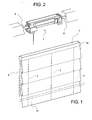
- Figure 1 illustrates, purely by way of example, a perspective view of a Roman blind provided with an assembly for winding the suspension cords of the blind, said assembly being made in conformance with the teachings of the present invention.
- the invention may be applied to any type of blind which uses suspension cords and hence not only to Roman blinds, but also, for example, to Venetian blinds or pleated blinds.
- the Roman blind comprises a blind fabric 1 having a top edge 1a secured via connection means of any known type, for example via a Velcro (registered trademark) connection, to a fixed supporting sectional strip 2, which is in turn secured, for example, to a wall or to a ceiling adjacent to a window of a building.
- the movement of raising and lowering of the blind is controlled by a plurality of suspension cords 3, each of which has a bottom end secured to the bottom edge 1b of the fabric of the blind 1 and can be wound, at the top, on a respective winding device 4 ( Figure 2) made in conformance with the present invention.
- the winding devices 4 are connected in rotation on a control shaft 5, which, in the example illustrated, has a square cross section and is supported at its ends in rotation about its axis by respective supports rigidly connected to the sectional strip 2.
- Rotation of the control shaft 5 is controlled by means of a control transmission of any known type, for example, as illustrated specifically in Figure 1, via a chain 6 wound to form a closed loop, which engages, at the top, a toothed wheel or pulley (not visible in the drawings) which is connected in rotation to the shaft 5 and hangs down underneath to a height that can be reached by the user.
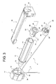
- each winding device 4 comprises a winding roller 8.
- the winding roller 8 has a body 9 with tubular conformation having one open end 10 and, at the other end, a bottom wall 11, from which there extends an axial shank 12, which has an axial hole 13 with square cross section designed to be engaged by the control shaft 5 with square cross section (see Figure 2).
- the tubular body 9 has an outer surface having, in the cross-sectional view, a circular profile with a substantially constant diameter (except for slight variations due to the tolerances of fabrication) throughout the length of the body 9.
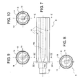
- a number of longitudinal grooves 14 arranged angularly at the same distance apart from one another. In the specific case illustrated, six grooves are provided, but obviously the number of said grooves may be different. In particular, it is in theory possible also to envisage a roller 8 having a single groove 14.
- each groove 14 has a depth that is constant along the tubular body 9 and a width, in the circumferential direction, increasing in a continuous way from one end adjacent to the axial shank 12 to the opposite end, in a position corresponding to the mouth 10 of the tubular body 9. More precisely, as illustrated in Figure 7, each groove 14 has an initial stretch 14a (comprised between the lines of section VIII and IX in Figure 7) where the increase in width of the groove along the roller is more rapid, and a second stretch 14b where the increase in width of the groove is less marked.
- Figures 8, 9, 10 represent cross-sectional views according to the lines VIII, IX and X of Figure 7 in order to show clearly the variation in width of each groove 14 at different sections of the roller.
- Figures 8A, 9A, 10A are views at a further enlarged scale of the detail of the cross section of the groove in positions corresponding to the planes of section mentioned above.
- the depth of each groove remains substantially constant along its length. Consequently, the profile of each groove remains always tangential to an internal circumference having its centre on the axis 8a of the roller 8 and a constant radius R2.
- Figures 8A, 9A, 10A also show clearly how the width of the groove 14 passes from the smaller value L of Figure 8A to the larger value L1 of Figure 9A and to the still larger value L2 of Figure 10A.
- the provision of grooves 14 having constant depth along the roller constitutes a preferred but not essential characteristic of the invention so that it is also possible to envisage grooves that have a variable depth along the roller.
- An essential characteristic of the invention is constituted by the increase in the width of each groove 14 along the roller. Also with reference to said characteristic, it should be considered that said increasing width is herein illustrated as developing throughout the length of each groove. However, the possibility is not ruled out that the grooves will have an increasing width only for a certain stretch of their length, and that they will present a final stretch having a width that is constant or, in any case, not increasing.
- a further preferred characteristic that may be clearly deduced from Figures 8A, 9A, 10A lies in the fact that the tubular body 9 of the roller 8 has a cross section with a theoretical external profile that is circular, concentric with the axis 8a of the roller 8 and a radius R1 that is constant throughout the roller.
- each groove 14 will present in its cross section, in a position corresponding to its end adjacent to the axial shank 12, a substantially V-shaped profile, said profile progressively widening (see Figure 9A) until it becomes a substantially flat profile (see Figure 10A).
- a further preferred characteristic of the roller 8 consists in the provision on its outer surface of an annular contrast surface 15, which, in the example illustrated, is defined by an edge with an enlarged diameter of the bottom wall 11 (see Figure 5).
- an annular contrast surface 15 which, in the example illustrated, is defined by an edge with an enlarged diameter of the bottom wall 11 (see Figure 5).
- a contrast surface 16 defined on a fixed body 17, designed to be fixed to the fixed sectional strip 2, the structure and function of which will be described in greater detail in what follows.
- the contrast surface 15 is made directly on the roller 9, but it is by no means ruled out that it can be defined by an element (for example a ring) mounted rigidly on the roller.
- the roller 8 is mounted so that it rotates about its axis 8a on two fixed end supports, one of which is constituted by the body 17 already mentioned above and the other by a further support 18.
- the support 18 has a horizontal wall 19 designed to be secured, via connection means of any known type, for example to the fixed support 17 or to any other fixed retention structure, and a vertical wall 20, which bestows on the element 18, together with the wall 19, a substantially L-shaped general configuration.
- the wall 20 has a circular through hole 21 within which there is supported, in such a way that it is able to rotate, a hub 22 forming part of a closing element 23 having an axial shank 24, which is received by and withheld within the end mouth 10 of the tubular body 9 of the roller 8.
- the closing element 23 moreover has an axial through hole 25 with square cross section, for engagement of the control shaft 5 of corresponding cross section.
- All the aforesaid components, including the roller 8, are preferably made of plastic material.
- auxiliary support 26 secured to which is the top end of a suspension cord 3.
- the support 26 which has a substantially C-shaped configuration, has a hole 27, through which the cord 3 can be engaged. There can then be made a knot 28 at one end of the cord 7 to prevent the cord from sliding out of the hole 27.
- the C-shaped body of the auxiliary support 26 is shaped so as to enable it to be fitted rapidly on the body of the closing element 23 in such a way as to be rigidly connected thereto.
- the body of the support 26 has two elastically deformable flaps terminating with engagement teeth 30 with corresponding seats made in the body of the element 23 (not visible in the plate of drawings), as well as a pair of ribbings 31 designed to be received in corresponding seats (not visible either in the plate drawings) of the body of the closing element 23.
- auxiliary support 29 makes it possible to connect the top end of the cord 3 to the body of the roller 8, or else to remove said connection, with extremely simple and fast operations, which render it particularly convenient for the user to put the blind up and to take it down whenever it is necessary, for example, to wash it or to carry out maintenance operations, as well as, of course, when the device is initially installed.
- the roller 8 is supported so that it can rotate by means of engagement of its axial shank 12 within a through hole 32 of a vertical wall 33 of the fixed body 17.
- Said body has a general box-like configuration, which defines a front cavity 34, arranged within which is a base portion 12a with enlarged diameter of the axial shank 12.
- the body 17, as already mentioned above, also defines, along the front edge of the cavity 34, the contrast surface 16, which is substantially coplanar to the annular contrast surface 15 defined above the tubular body 9 of the roller 8.
- the fixed body 17 has a horizontal bottom wall 35, defined in which is a passage 36 for the cord 3.
- the passage 36 that guides the cord 3 towards the roller 8 is positioned at a distance from the plane of the contrast surfaces 15, 16 and is located on a side of said plane opposite to the area of anchorage of the cord 3 to the roller 8, defined by the auxiliary support 26.
- control shaft 5 When it is desired to raise the blind, the control shaft 5 is set in rotation in order transmit, directly or via a corresponding transmission, a rotation to the roller 8. Rotation of the roller 8 consequently sets in rotation also the anchorage support 26 of the top end of the cord 3, which is thus forced to wind on the tubular body 9 of the roller.
- Figure 5 illustrates the condition reached after a few turns of rotation of the roller.
- turns of cord 3 with some of said turns arranged in the immediate vicinity of the contrast surfaces 15, 16.
- the turns start to form in said position, and are then progressively displaced towards the right (with reference to Figure 5) i.e., in the direction of the support 26 for anchorage of the end of the cord 3.
- the conformation illustrated above of the roller 8, and in particular the arrangement of the grooves 14 having the specific geometry described above favours progressive sliding of the turns of the cord 3, which form initially in a position adjacent to the contrast surfaces 15, 16, in the direction of the anchorage support 26, in such a way as to exclude, or in any case render minimal, any risk of overlapping between different turns during winding of the cord.
- Said phenomenon is due mainly to the fact that the turns that are displaced progressively along portions of increasing width of the grooves 14 undergo slackening, which consequently favours their sliding towards the right-hand end (as viewed in Figure 5) of the roller.
- the turns that have instead already been formed and are still adjacent to the contrast surfaces 15, 16 are, instead, wound in a relatively tight way around the roller so as to prevent that the tension on the stretch of cord 3 subjected to the weight of the blind is transmitted to the turns that are instead already in a position corresponding to the part furthest to the right (again as viewed in Figure 5) of the roller. Thanks to this phenomenon, the turns that are axially sliding along the roller, owing to the slackening caused by the specific conformation of the grooves 14, are not "pulled” by the part of cord 3 set "upstream” and subject to the weight of the blind.
- said phenomenon is presumed to be encouraged by the very fact that the arrangement of the aforesaid grooves 14 entails a global reduction in the contact surface between the cord wound on the roller and the roller itself, said phenomenon increasing as the turns come close to the anchorage support 26 as a result of the increase in width of the grooves 14.
- the tubular body 9 of the roller 8 had an axial length of 68.5 mm (the grooved part), an outer diameter of 19 mm, with grooves 14 having a width increasing from 1.4 mm to 7 mm in a first stretch 14a having a length of 6.8 mm, and a width increasing from 7 mm to 8 mm in a second stretch 14b having a length of 61.7 mm (i.e., as far as the end of the roller).
- the depth of each groove 14a was 1 mm.
- the structure and arrangement of the parts designed to support the roller 8 in rotation could even be altogether different from the one described herein purely by way of example.
- the general conformation of the roller 8 could be different, i.e., it could even be constituted by a full body, or else a tubular body which, instead of having the grooves 14, is provided with through slits having a similar configuration.
- just one roller which has throughout its length various areas having a conformation corresponding to that of the roller 8 illustrated herein, for winding thereon various suspension cords of the blind.
- the grooves or slits provided on the roller could also have a constant width.
- the roller must have one initial portion without any grooves or slits. Passage from the portion without grooves or slits to the adjacent one brings about slackening of the turns, which is a determining factor for proper operation of the device.
Abstract
Description
- The present invention relates to devices for winding suspension cords of blinds, of the type including a winding roller, fixed to which is the end of at least one suspension cord, and means for ensuring that the cord is wound in orderly turns on the roller, without any overlapping.
- A device of the type specified above is, for example, described and illustrated in the European patent EP 0 554 212 B1. In said known device, the winding roller is equipped with one portion presenting a (step-like or continuous) reduction of diameter in order to favour axial sliding over it of the turns of cord that are formed on the roller during rotation thereof. The axial displacement of the turns along said portion with decreasing diameter prevents any risk of overlapping.
- Studies and tests conducted by the present applicant have however shown that the aforesaid known solution is not always completely satisfactory.
- A purpose of the present invention is consequently to overcome the aforesaid drawback, providing a device that will be simple, as well as reliable and efficient as regards operation.
- A further purpose underlying the invention is to provide a device of the type specified above that will be simple and convenient for the user, also as regards the operations necessary for installing the blind, or for taking it down and it putting up whenever it is necessary to proceed to washing it or to carrying out maintenance operations.
- With a view to achieving the aforesaid purposes, the subject of the invention is a device presenting the characteristics indicated at the beginning of the present description and characterized moreover in that the aforesaid means for ensuring that the cord is wound in orderly turns on the roller without any overlapping comprise at least one longitudinal groove or slit, made in the winding roller.
- Preferably, said groove has, at least for one portion of its length, a width, in the circumferential direction of the roller, that increases along the roller, in the direction of the area for fixing the cord to the roller.
- Thanks to said characteristic, even though the winding roller of the device according to the invention can be made (unlike the known solution mentioned above) with a cross section having constant diameter along the roller, it enables the risk of overlapping of the turns of the cord during winding thereof to be eliminated altogether or to be reduced to a minimum.
- The aforesaid result has been verified by the present applicant with experimental tests conducted on a concrete embodiment of the present invention. The physical phenomenon that underlies said result has not yet been totally explained. The probable reason for the better operation of the device according to the invention as compared to known solutions lies in the fact that whenever a new turn is formed on the roller, it manages to displace the already existing ones, in so far as these, on account of the particular grooved conformation of the roller, reduce the grip on the roller and loosen off just enough to cause their axial sliding along the roller.
- In the preferred embodiment of the device according to the invention, the portion of the roller on which the cord is wound has a cross section with an external profile with a circular shape, having a constant diameter along the roller.
- According to a further characteristic of the invention, the device comprises an axial contrast surface, adjacent to the roller and close to one end of the groove or slit, or of each groove or slit, opposite to the area for fixing of the cord.
- The aforesaid axial contrast surface may be defined on the surface of the roller or on an element connected to the roller, or else on a fixed support adjacent to the roller, or else again partly on the roller and partly on a fixed support, which applies in the case of the aforesaid preferred embodiment.
- Again in the case of the preferred embodiment, there are provided a number of longitudinal grooves, which are arranged angularly at the same distance apart from one another.
- Again in the case of the preferred embodiment, there are provided grooves of longitudinally constant depth.
- In the case where the winding roller has a tubular body, there may also be envisaged, instead of the aforesaid grooves, through slits made in the wall of the tubular body, having in any case the characteristic mentioned above consisting in their width which increases along the roller.
- In the concrete embodiment that will be illustrated by way of example, each groove has moreover a width that increases more rapidly in a first stretch of the roller and less rapidly in a second stretch which is nearer to the area for fixing of the cord.
- As an additional advantage as regards simplicity and convenience of use, in the area for fixing of the cord there is provided an auxiliary support, to which one end of the cord is secured and which is provided with means for fast attachment to the roller or to a part connected to the roller. The operation of putting up and taking down the blind, in particular whenever it is necessary to proceed to washing it, consequently proves particularly simple and fast.
- Further characteristics and advantages of the present invention will emerge from the ensuing description with reference to the annexed drawings, which are provided purely by way of non-limiting example, and in which:
- Figure 1 is a schematic perspective view of a blind provided with a plurality of devices according to the present invention;
- Figure 2 is a schematic perspective view at an enlarged scale of a detail of Figure 1;
- Figure 3 is an exploded perspective view of a winding device of the type illustrated in Figure 2;
- Figure 4 is a cross-sectional view of the device of Figure 3 in a plane perpendicular to the axis of the winding roller;
- Figure 5 is a cross-sectional view according to the line V-V of Figure 4;
- Figure 6 illustrates a detail of Figure 5, in a different operating condition;
- Figure 7 is a side view of the winding roller forming part of the device of Figure 3;
- Figures 8, 9, 10 are cross-sectional views according to the lines VIII-VIII, IX-IX and X-X of Figure 7, respectively; and
- Figures 8A, 9A, 10A are views at an enlarged scale of details of Figures 8, 9, 10, respectively.
- Figure 1 illustrates, purely by way of example, a perspective view of a Roman blind provided with an assembly for winding the suspension cords of the blind, said assembly being made in conformance with the teachings of the present invention. Of course, the invention may be applied to any type of blind which uses suspension cords and hence not only to Roman blinds, but also, for example, to Venetian blinds or pleated blinds.
- In the case of the example illustrated, the Roman blind comprises a blind fabric 1 having a
top edge 1a secured via connection means of any known type, for example via a Velcro (registered trademark) connection, to a fixed supportingsectional strip 2, which is in turn secured, for example, to a wall or to a ceiling adjacent to a window of a building. The movement of raising and lowering of the blind is controlled by a plurality ofsuspension cords 3, each of which has a bottom end secured to thebottom edge 1b of the fabric of the blind 1 and can be wound, at the top, on a respective winding device 4 (Figure 2) made in conformance with the present invention. As may be seen in Figure 2, thewinding devices 4 are connected in rotation on acontrol shaft 5, which, in the example illustrated, has a square cross section and is supported at its ends in rotation about its axis by respective supports rigidly connected to thesectional strip 2. Rotation of thecontrol shaft 5 is controlled by means of a control transmission of any known type, for example, as illustrated specifically in Figure 1, via achain 6 wound to form a closed loop, which engages, at the top, a toothed wheel or pulley (not visible in the drawings) which is connected in rotation to theshaft 5 and hangs down underneath to a height that can be reached by the user. - The structure and operation of an individual winding device will be now illustrated with reference to Figures 3-10A. With reference in particular to Figure 3, each
winding device 4 comprises awinding roller 8. As illustrated more clearly in Figure 5, thewinding roller 8 has abody 9 with tubular conformation having oneopen end 10 and, at the other end, abottom wall 11, from which there extends anaxial shank 12, which has anaxial hole 13 with square cross section designed to be engaged by thecontrol shaft 5 with square cross section (see Figure 2). Thetubular body 9 has an outer surface having, in the cross-sectional view, a circular profile with a substantially constant diameter (except for slight variations due to the tolerances of fabrication) throughout the length of thebody 9. Made in said surface are a number oflongitudinal grooves 14 arranged angularly at the same distance apart from one another. In the specific case illustrated, six grooves are provided, but obviously the number of said grooves may be different. In particular, it is in theory possible also to envisage aroller 8 having asingle groove 14. - With reference in particular to Figure 7-10A, each
groove 14 has a depth that is constant along thetubular body 9 and a width, in the circumferential direction, increasing in a continuous way from one end adjacent to theaxial shank 12 to the opposite end, in a position corresponding to themouth 10 of thetubular body 9. More precisely, as illustrated in Figure 7, eachgroove 14 has aninitial stretch 14a (comprised between the lines of section VIII and IX in Figure 7) where the increase in width of the groove along the roller is more rapid, and asecond stretch 14b where the increase in width of the groove is less marked. Figures 8, 9, 10 represent cross-sectional views according to the lines VIII, IX and X of Figure 7 in order to show clearly the variation in width of eachgroove 14 at different sections of the roller. Figures 8A, 9A, 10A are views at a further enlarged scale of the detail of the cross section of the groove in positions corresponding to the planes of section mentioned above. As may be clearly seen in said figures, in the case of the example illustrated, the depth of each groove remains substantially constant along its length. Consequently, the profile of each groove remains always tangential to an internal circumference having its centre on theaxis 8a of theroller 8 and a constant radius R2. Figures 8A, 9A, 10A also show clearly how the width of thegroove 14 passes from the smaller value L of Figure 8A to the larger value L1 of Figure 9A and to the still larger value L2 of Figure 10A. Of course, the provision ofgrooves 14 having constant depth along the roller constitutes a preferred but not essential characteristic of the invention so that it is also possible to envisage grooves that have a variable depth along the roller. - An essential characteristic of the invention is constituted by the increase in the width of each
groove 14 along the roller. Also with reference to said characteristic, it should be considered that said increasing width is herein illustrated as developing throughout the length of each groove. However, the possibility is not ruled out that the grooves will have an increasing width only for a certain stretch of their length, and that they will present a final stretch having a width that is constant or, in any case, not increasing. - A further preferred characteristic that may be clearly deduced from Figures 8A, 9A, 10A lies in the fact that the
tubular body 9 of theroller 8 has a cross section with a theoretical external profile that is circular, concentric with theaxis 8a of theroller 8 and a radius R1 that is constant throughout the roller. - Again with reference to Figures 8A, 9A, 10A, it may be noted how, following upon the variation in the width of each
groove 14, the latter will present in its cross section, in a position corresponding to its end adjacent to theaxial shank 12, a substantially V-shaped profile, said profile progressively widening (see Figure 9A) until it becomes a substantially flat profile (see Figure 10A). - A further preferred characteristic of the
roller 8 consists in the provision on its outer surface of anannular contrast surface 15, which, in the example illustrated, is defined by an edge with an enlarged diameter of the bottom wall 11 (see Figure 5). Again according to a further preferred characteristic of the invention, in addition to thecontrast surface 15 made on theroller 8, there is also provided acontrast surface 16 defined on afixed body 17, designed to be fixed to the fixedsectional strip 2, the structure and function of which will be described in greater detail in what follows. In the case of the example illustrated, thecontrast surface 15 is made directly on theroller 9, but it is by no means ruled out that it can be defined by an element (for example a ring) mounted rigidly on the roller. - Once again with reference to Figures 3 and 5, the
roller 8 is mounted so that it rotates about itsaxis 8a on two fixed end supports, one of which is constituted by thebody 17 already mentioned above and the other by afurther support 18. Thesupport 18 has ahorizontal wall 19 designed to be secured, via connection means of any known type, for example to thefixed support 17 or to any other fixed retention structure, and avertical wall 20, which bestows on theelement 18, together with thewall 19, a substantially L-shaped general configuration. Thewall 20 has a circular throughhole 21 within which there is supported, in such a way that it is able to rotate, a hub 22 forming part of aclosing element 23 having anaxial shank 24, which is received by and withheld within theend mouth 10 of thetubular body 9 of theroller 8. Theclosing element 23 moreover has an axial throughhole 25 with square cross section, for engagement of thecontrol shaft 5 of corresponding cross section. - All the aforesaid components, including the
roller 8, are preferably made of plastic material. - Associated to the
closing element 23 is anauxiliary support 26, secured to which is the top end of asuspension cord 3. For this purpose, thesupport 26, which has a substantially C-shaped configuration, has ahole 27, through which thecord 3 can be engaged. There can then be made aknot 28 at one end of thecord 7 to prevent the cord from sliding out of thehole 27. The C-shaped body of theauxiliary support 26 is shaped so as to enable it to be fitted rapidly on the body of theclosing element 23 in such a way as to be rigidly connected thereto. In the example illustrated, for said purpose, the body of thesupport 26 has two elastically deformable flaps terminating withengagement teeth 30 with corresponding seats made in the body of the element 23 (not visible in the plate of drawings), as well as a pair ofribbings 31 designed to be received in corresponding seats (not visible either in the plate drawings) of the body of theclosing element 23. - The provision of the
auxiliary support 29 evidently makes it possible to connect the top end of thecord 3 to the body of theroller 8, or else to remove said connection, with extremely simple and fast operations, which render it particularly convenient for the user to put the blind up and to take it down whenever it is necessary, for example, to wash it or to carry out maintenance operations, as well as, of course, when the device is initially installed. - At the opposite end, the
roller 8 is supported so that it can rotate by means of engagement of itsaxial shank 12 within a throughhole 32 of avertical wall 33 of the fixedbody 17. Said body has a general box-like configuration, which defines afront cavity 34, arranged within which is abase portion 12a with enlarged diameter of theaxial shank 12. Thebody 17, as already mentioned above, also defines, along the front edge of thecavity 34, thecontrast surface 16, which is substantially coplanar to theannular contrast surface 15 defined above thetubular body 9 of theroller 8. - Finally, the fixed
body 17 has ahorizontal bottom wall 35, defined in which is apassage 36 for thecord 3. - As may be clearly seen in Figure 5, in the installed condition of the device, the
passage 36 that guides thecord 3 towards theroller 8 is positioned at a distance from the plane of the contrast surfaces 15, 16 and is located on a side of said plane opposite to the area of anchorage of thecord 3 to theroller 8, defined by theauxiliary support 26. Even this characteristic, albeit being preferred, is not however essential for the purposes of application of the ideas that underlie the present invention. - Operation of the device described above is described in what follows.
- When the blind is in its completely lowered condition, the top final stretch of the
cord 3 extends, starting from theanchorage support 26, directly towards the guidingpassage 36, underneath theroller 8. In this condition, consequently, thecord 3 is not wound to any extent on theroller 8. - When it is desired to raise the blind, the
control shaft 5 is set in rotation in order transmit, directly or via a corresponding transmission, a rotation to theroller 8. Rotation of theroller 8 consequently sets in rotation also theanchorage support 26 of the top end of thecord 3, which is thus forced to wind on thetubular body 9 of the roller. - Figure 5 illustrates the condition reached after a few turns of rotation of the roller. As may be seen, in this condition, on the roller there have already been formed turns of
cord 3, with some of said turns arranged in the immediate vicinity of the contrast surfaces 15, 16. In effect, during rotation of the roller, the turns start to form in said position, and are then progressively displaced towards the right (with reference to Figure 5) i.e., in the direction of thesupport 26 for anchorage of the end of thecord 3. - As verified experimentally by the present applicant, the conformation illustrated above of the
roller 8, and in particular the arrangement of thegrooves 14 having the specific geometry described above, favours progressive sliding of the turns of thecord 3, which form initially in a position adjacent to the contrast surfaces 15, 16, in the direction of theanchorage support 26, in such a way as to exclude, or in any case render minimal, any risk of overlapping between different turns during winding of the cord. Said phenomenon is due mainly to the fact that the turns that are displaced progressively along portions of increasing width of thegrooves 14 undergo slackening, which consequently favours their sliding towards the right-hand end (as viewed in Figure 5) of the roller. In this step, the turns that have instead already been formed and are still adjacent to the contrast surfaces 15, 16 are, instead, wound in a relatively tight way around the roller so as to prevent that the tension on the stretch ofcord 3 subjected to the weight of the blind is transmitted to the turns that are instead already in a position corresponding to the part furthest to the right (again as viewed in Figure 5) of the roller. Thanks to this phenomenon, the turns that are axially sliding along the roller, owing to the slackening caused by the specific conformation of thegrooves 14, are not "pulled" by the part ofcord 3 set "upstream" and subject to the weight of the blind. Furthermore, said phenomenon is presumed to be encouraged by the very fact that the arrangement of theaforesaid grooves 14 entails a global reduction in the contact surface between the cord wound on the roller and the roller itself, said phenomenon increasing as the turns come close to theanchorage support 26 as a result of the increase in width of thegrooves 14. - Above and beyond of the aforesaid theoretical explanations, the fact in any case remains that the device described above is able to operate in an efficient and reliable way, as has been found experimentally by the present applicant, guaranteeing results that are even better than the ones obtained with the devices according to the known art.
- In order to obtain properly the effect described above, it may be beneficial (even though not essential or determinate) to position the guiding
passage 36 at a distance from the plane of the contrast surfaces 15, 16, according to what has been described above. Furthermore, also particularly advantageous is the provision of twocontrast surfaces roller 8 and on the fixed structure, respectively. It is however evident that it would also be possible to envisage a contrast surface only on the roller, or else a contrast surface only on the fixed structure. Likewise, it is not excluded that, in certain applications, it is possible to envisage a roller without contrast surfaces. - In a concrete example of embodiment of the device illustrated above, the
tubular body 9 of theroller 8 had an axial length of 68.5 mm (the grooved part), an outer diameter of 19 mm, withgrooves 14 having a width increasing from 1.4 mm to 7 mm in afirst stretch 14a having a length of 6.8 mm, and a width increasing from 7 mm to 8 mm in asecond stretch 14b having a length of 61.7 mm (i.e., as far as the end of the roller). In this concrete example of embodiment, the depth of eachgroove 14a was 1 mm. - Of course, without prejudice to the principle of the invention, the details of construction and the embodiments may vary widely with respect to what is described and illustrated herein purely by way of example.
- In particular, the structure and arrangement of the parts designed to support the
roller 8 in rotation could even be altogether different from the one described herein purely by way of example. Also the general conformation of theroller 8 could be different, i.e., it could even be constituted by a full body, or else a tubular body which, instead of having thegrooves 14, is provided with through slits having a similar configuration. Likewise not ruled out is the possibility of just one roller, which has throughout its length various areas having a conformation corresponding to that of theroller 8 illustrated herein, for winding thereon various suspension cords of the blind. - In addition the grooves or slits provided on the roller could also have a constant width. In this case, the roller must have one initial portion without any grooves or slits. Passage from the portion without grooves or slits to the adjacent one brings about slackening of the turns, which is a determining factor for proper operation of the device.
Claims (16)
- A device for winding the suspension cord (3) of a blind, including:characterized in that said means comprise at least one longitudinal groove or slit (14) made in the winding roller (8).a winding roller (8) fixed to which is the end of at least one suspension cord (3); andmeans for ensuring that the cord (3) is wound in orderly turns on the roller (8) without any overlapping,
- The device according to Claim 1, characterized in that said longitudinal groove or slit has, at least for one portion of its length, a width (understood as dimension in the circumferential direction of the roller (8)) that increases along the roller (8) in the direction of the area (26) for fixing of the cord (3) to the roller (8).
- The device according to Claim 2, characterized in that the portion of the roller (8) on which the cord is wound (3) has a cross section with an external profile having dimensions substantially constant throughout the roller (8).
- The device according to Claim 2, characterized in that said device comprises an axial contrast surface (15,16) adjacent to the roller (8) and close to one end of said groove (14) or slit opposite to the area for fixing of the cord.
- The device according to Claim 4, characterized in that said axial contrast surface (15) is defined on the surface of the roller (8) or of an element connected to the roller (8).
- The device according to Claim 4, characterized in that said axial contrast surface (16) is defined by a fixed support (2) adjacent to the roller (8).
- The device according to Claim 4, characterized in that said axial contrast surface (15,16) is defined partly on the surface of the roller (8) or of an element connected to the roller (8) and partly on a fixed support (2) adjacent to the roller (8).
- The device according to Claim 2, characterized in that there are provided a number of longitudinal grooves (14) or slits.
- The device according to Claim 8, characterized in that the grooves (14) or slits are arranged angularly at the same distance apart from one another.
- The device according to Claim 2, characterized in that said means comprise at least one groove (14) with longitudinally constant depth.
- The device according to Claim 2, characterized in that the roller (8) has a tubular body (9) and in that said means comprise at least one through slit made in the wall of said tubular body.
- The device according to Claim 2, characterized in that the groove (14) or slit has a width increasing more rapidly in a first stretch (14a) and less rapidly in a second stretch (14b), which is nearer to the area for fixing of the cord (3).
- The device according to Claim 2, characterized in that provided in the area for fixing of the cord (3) is an auxiliary support (26), secured to which is one end of the cord (3), and in that said device is provided with means of fast attachment (29-31) to the roller (8) or to an element fixed to the roller.
- A winding assembly for a plurality of suspension cords (3) of a blind, comprising a plurality of devices according to one or more of the preceding claims, controlled by a common control element (15).
- A blind assembly comprising a winding assembly according to Claim 14.
- The blind assembly comprising at least one device according to one or more of Claims 1-13.
Priority Applications (1)
| Application Number | Priority Date | Filing Date | Title |
|---|---|---|---|
| EP04425191A EP1577483A1 (en) | 2004-03-18 | 2004-03-18 | Device for winding a suspension cord of a blind |
Applications Claiming Priority (1)
| Application Number | Priority Date | Filing Date | Title |
|---|---|---|---|
| EP04425191A EP1577483A1 (en) | 2004-03-18 | 2004-03-18 | Device for winding a suspension cord of a blind |
Publications (1)
| Publication Number | Publication Date |
|---|---|
| EP1577483A1 true EP1577483A1 (en) | 2005-09-21 |
Family
ID=34833840
Family Applications (1)
| Application Number | Title | Priority Date | Filing Date |
|---|---|---|---|
| EP04425191A Withdrawn EP1577483A1 (en) | 2004-03-18 | 2004-03-18 | Device for winding a suspension cord of a blind |
Country Status (1)
| Country | Link |
|---|---|
| EP (1) | EP1577483A1 (en) |
Cited By (4)
| Publication number | Priority date | Publication date | Assignee | Title |
|---|---|---|---|---|
| GB2423785A (en) * | 2006-01-27 | 2006-09-06 | Ke-Min Lin | Winding device for a Venetian blind |
| EP1983143A1 (en) | 2007-04-20 | 2008-10-22 | Somfy SAS | Device for winding a suspension cord comprising means for guiding the cord |
| WO2011128028A2 (en) | 2010-04-16 | 2011-10-20 | Hunter Douglas Industries B.V. | Conical cord-winding spool with circumferential steps |
| CN108825103A (en) * | 2018-07-25 | 2018-11-16 | 江苏赛迪乐节能科技有限公司 | The withdrawing rope device of double layer glass window with built-in louver |
Citations (2)
| Publication number | Priority date | Publication date | Assignee | Title |
|---|---|---|---|---|
| EP0554212A1 (en) | 1992-01-30 | 1993-08-04 | Somfy | Winding mechanism for the suspension cords of a venetian blind |
| EP1431508A2 (en) * | 2002-12-19 | 2004-06-23 | Hunter Douglas Industries B.V. | Raising and lowering mechanism for blinds |
-
2004
- 2004-03-18 EP EP04425191A patent/EP1577483A1/en not_active Withdrawn
Patent Citations (2)
| Publication number | Priority date | Publication date | Assignee | Title |
|---|---|---|---|---|
| EP0554212A1 (en) | 1992-01-30 | 1993-08-04 | Somfy | Winding mechanism for the suspension cords of a venetian blind |
| EP1431508A2 (en) * | 2002-12-19 | 2004-06-23 | Hunter Douglas Industries B.V. | Raising and lowering mechanism for blinds |
Cited By (5)
| Publication number | Priority date | Publication date | Assignee | Title |
|---|---|---|---|---|
| GB2423785A (en) * | 2006-01-27 | 2006-09-06 | Ke-Min Lin | Winding device for a Venetian blind |
| GB2423785B (en) * | 2006-01-27 | 2007-03-21 | Ke-Min Lin | Winding device for venetian blind |
| EP1983143A1 (en) | 2007-04-20 | 2008-10-22 | Somfy SAS | Device for winding a suspension cord comprising means for guiding the cord |
| WO2011128028A2 (en) | 2010-04-16 | 2011-10-20 | Hunter Douglas Industries B.V. | Conical cord-winding spool with circumferential steps |
| CN108825103A (en) * | 2018-07-25 | 2018-11-16 | 江苏赛迪乐节能科技有限公司 | The withdrawing rope device of double layer glass window with built-in louver |
Similar Documents
| Publication | Publication Date | Title |
|---|---|---|
| US5813447A (en) | Cordless cellular and pleated shade | |
| US20160208551A1 (en) | Window Shade and Control System Thereof | |
| EP3751090B1 (en) | Cordless roller blind | |
| EP2131008B1 (en) | Window Covering | |
| RU2118439C1 (en) | Control mechanism with sleeve for rolling-up curtains | |
| EP3513028B1 (en) | Adjustable spring system and method for roller blinds | |
| CA2277603A1 (en) | A winding and unwinding mechanism for blinds and or shades | |
| US9140060B2 (en) | Window covering having at least one deformable connector | |
| US20120216966A1 (en) | Lift Mechanisms for Venetian Blind | |
| US20170321476A1 (en) | Driving assembly and window blind | |
| EP1577483A1 (en) | Device for winding a suspension cord of a blind | |
| KR20120008562U (en) | Tention control apparatus for Electric motion type blind system | |
| KR100728938B1 (en) | Blind | |
| US9482050B2 (en) | Shade lock assembly | |
| KR20110011573U (en) | Honeycomb Shade | |
| KR940004904Y1 (en) | Operating device of electric drive blind | |
| KR200359541Y1 (en) | Roll blind with improved structure for regulating a light | |
| KR100626122B1 (en) | Moving device of slat used for blind | |
| KR200305692Y1 (en) | A winding device for the blind | |
| KR20170122567A (en) | Cord winding drum for wood blind | |
| ITCO20100012U1 (en) | DEVICE FOR ALLOWING TO RAISE / LOWER AND ORIENT A VENETIAN | |
| KR102492330B1 (en) | Drive for roll blinds operated by a single wire | |
| KR101313893B1 (en) | Device for operating blind with low noise | |
| KR200340030Y1 (en) | Roll blind with improved function for regulating a light | |
| KR20230094292A (en) | Screen up and down apparatus of electric blind |
Legal Events
| Date | Code | Title | Description |
|---|---|---|---|
| PUAI | Public reference made under article 153(3) epc to a published international application that has entered the european phase |
Free format text: ORIGINAL CODE: 0009012 |
|
| 17P | Request for examination filed |
Effective date: 20041227 |
|
| AK | Designated contracting states |
Kind code of ref document: A1 Designated state(s): AT BE BG CH CY CZ DE DK EE ES FI FR GB GR HU IE IT LI LU MC NL PL PT RO SE SI SK TR |
|
| AX | Request for extension of the european patent |
Extension state: AL LT LV MK |
|
| AKX | Designation fees paid |
Designated state(s): AT BE BG CH CY CZ DE DK EE ES FI FR GB GR HU IE IT LI LU MC NL PL PT RO SE SI SK TR |
|
| 17Q | First examination report despatched |
Effective date: 20060301 |
|
| 17Q | First examination report despatched |
Effective date: 20060301 |
|
| STAA | Information on the status of an ep patent application or granted ep patent |
Free format text: STATUS: THE APPLICATION IS DEEMED TO BE WITHDRAWN |
|
| 18D | Application deemed to be withdrawn |
Effective date: 20070616 |