EP1577179A2 - Procédé et système de mise hors fonction de papillon - Google Patents
Procédé et système de mise hors fonction de papillon Download PDFInfo
- Publication number
- EP1577179A2 EP1577179A2 EP05075278A EP05075278A EP1577179A2 EP 1577179 A2 EP1577179 A2 EP 1577179A2 EP 05075278 A EP05075278 A EP 05075278A EP 05075278 A EP05075278 A EP 05075278A EP 1577179 A2 EP1577179 A2 EP 1577179A2
- Authority
- EP
- European Patent Office
- Prior art keywords
- signal
- ecm
- vehicle
- input
- input signal
- Prior art date
- Legal status (The legal status is an assumption and is not a legal conclusion. Google has not performed a legal analysis and makes no representation as to the accuracy of the status listed.)
- Granted
Links
- 238000000034 method Methods 0.000 title claims abstract description 40
- 230000007246 mechanism Effects 0.000 claims abstract description 25
- 230000000593 degrading effect Effects 0.000 claims abstract description 14
- 238000010200 validation analysis Methods 0.000 claims description 33
- 238000004891 communication Methods 0.000 claims description 7
- 230000003213 activating effect Effects 0.000 claims description 4
- 230000000694 effects Effects 0.000 claims description 4
- 230000004913 activation Effects 0.000 claims 3
- 238000010586 diagram Methods 0.000 description 9
- 230000008901 benefit Effects 0.000 description 3
- 230000000994 depressogenic effect Effects 0.000 description 3
- 230000006870 function Effects 0.000 description 3
- 230000004888 barrier function Effects 0.000 description 2
- 230000006978 adaptation Effects 0.000 description 1
- 238000013459 approach Methods 0.000 description 1
- 230000006378 damage Effects 0.000 description 1
- 238000013461 design Methods 0.000 description 1
- 238000005516 engineering process Methods 0.000 description 1
- 230000001815 facial effect Effects 0.000 description 1
- 239000000446 fuel Substances 0.000 description 1
- 231100001261 hazardous Toxicity 0.000 description 1
- 230000003287 optical effect Effects 0.000 description 1
- 238000012545 processing Methods 0.000 description 1
- 230000004044 response Effects 0.000 description 1
- 239000007858 starting material Substances 0.000 description 1
- 230000001960 triggered effect Effects 0.000 description 1
Images


Classifications
-
- B—PERFORMING OPERATIONS; TRANSPORTING
- B60—VEHICLES IN GENERAL
- B60R—VEHICLES, VEHICLE FITTINGS, OR VEHICLE PARTS, NOT OTHERWISE PROVIDED FOR
- B60R25/00—Fittings or systems for preventing or indicating unauthorised use or theft of vehicles
- B60R25/01—Fittings or systems for preventing or indicating unauthorised use or theft of vehicles operating on vehicle systems or fittings, e.g. on doors, seats or windscreens
- B60R25/04—Fittings or systems for preventing or indicating unauthorised use or theft of vehicles operating on vehicle systems or fittings, e.g. on doors, seats or windscreens operating on the propulsion system, e.g. engine or drive motor
- B60R25/045—Fittings or systems for preventing or indicating unauthorised use or theft of vehicles operating on vehicle systems or fittings, e.g. on doors, seats or windscreens operating on the propulsion system, e.g. engine or drive motor by limiting or cutting the electrical supply to the propulsion unit
-
- B—PERFORMING OPERATIONS; TRANSPORTING
- B60—VEHICLES IN GENERAL
- B60R—VEHICLES, VEHICLE FITTINGS, OR VEHICLE PARTS, NOT OTHERWISE PROVIDED FOR
- B60R25/00—Fittings or systems for preventing or indicating unauthorised use or theft of vehicles
- B60R25/01—Fittings or systems for preventing or indicating unauthorised use or theft of vehicles operating on vehicle systems or fittings, e.g. on doors, seats or windscreens
- B60R25/04—Fittings or systems for preventing or indicating unauthorised use or theft of vehicles operating on vehicle systems or fittings, e.g. on doors, seats or windscreens operating on the propulsion system, e.g. engine or drive motor
- B60R25/042—Fittings or systems for preventing or indicating unauthorised use or theft of vehicles operating on vehicle systems or fittings, e.g. on doors, seats or windscreens operating on the propulsion system, e.g. engine or drive motor operating on the fuel supply
-
- B—PERFORMING OPERATIONS; TRANSPORTING
- B60—VEHICLES IN GENERAL
- B60R—VEHICLES, VEHICLE FITTINGS, OR VEHICLE PARTS, NOT OTHERWISE PROVIDED FOR
- B60R25/00—Fittings or systems for preventing or indicating unauthorised use or theft of vehicles
- B60R25/20—Means to switch the anti-theft system on or off
- B60R25/25—Means to switch the anti-theft system on or off using biometry
- B60R25/252—Fingerprint recognition
-
- B—PERFORMING OPERATIONS; TRANSPORTING
- B60—VEHICLES IN GENERAL
- B60R—VEHICLES, VEHICLE FITTINGS, OR VEHICLE PARTS, NOT OTHERWISE PROVIDED FOR
- B60R25/00—Fittings or systems for preventing or indicating unauthorised use or theft of vehicles
- B60R25/30—Detection related to theft or to other events relevant to anti-theft systems
- B60R25/33—Detection related to theft or to other events relevant to anti-theft systems of global position, e.g. by providing GPS coordinates
Definitions
- the present invention generally relates to security systems and more particularly relates to systems for disabling the movement of a vehicle.
- Vehicle security systems are primarily autonomous systems used to detect theft or vandalization of a vehicle, vehicle components, or unauthorized vehicle entry.
- protecting vehicles against theft or vandalism has become secondary, giving way to a primary concern of protecting citizens from vehicles that could possibly be used for mass destruction of property or human life.
- Vehicle disabling systems have been developed to disable a vehicle in a controlled manner, thereby allowing the vehicle's operator, at all times, to maintain control of the vehicle.
- the present invention provides a method and system for degrading and disabling a vehicle's engine throttle response in a safe manner.
- the present invention provides several advantages.
- One advantage of the present invention is that the method and system idles the throttle by reducing the power and not entirely cutting the power provided by the engine. Accordingly, the vehicle's driver is still able to control the throttle with reduced power without losing control of the vehicle's steering device and other engine-enabled mechanisms such as power brakes.
- Another advantage provided by the present invention is that the method and system is capable of idling the throttle of a vehicle driven by either the vehicle's regular driver or the vehicle's hijacker, without a distinction being first made between the two.
- the multistage disable method provides a way to slow down the vehicle to prevent the hijacker's escape (or the hijacker's use of the vehicle in an act of terrorism) while also providing for the safety of the vehicle's regular driver in the event that the driver is off course.
- the present invention provides a method of forcing the throttle to idle, the method including the steps of providing a vehicle disable system including a throttle position sensor; a throttle position signal line and an alternative signal line, both of the lines capable of being connected to the ECM input, the throttle position signal line including a switch to disconnect the throttle position signal line from the ECM input and connect said alternative signal line to the ECM input when switch means is activated; activating the switch; and transmitting an idling signal to the ECM on the ECM input to effect the idling of the throttle.
- a vehicle disable system including a throttle position sensor; a throttle position signal line and an alternative signal line, both of the lines capable of being connected to the ECM input, the throttle position signal line including a switch to disconnect the throttle position signal line from the ECM input and connect said alternative signal line to the ECM input when switch means is activated; activating the switch; and transmitting an idling signal to the ECM on the ECM input to effect the idling of the throttle.
- a vehicle disable system including a throttle position sensor having a driver input mechanism, the driver input mechanism indicating a state of the engine throttle varying between idle operation and non-idle operation, and the throttle position sensor also generating a throttle position signal related to the state of the driver input mechanism; an ECM input adapted to be connected to the ECM, the throttle position sensor providing the throttle position signal to the ECM on the ECM input; and an override input that enables an idling signal to be transmitted to the ECM on the ECM input in lieu of said throttle position signal.
- a method of reducing the throttle including the steps of receiving an input signal related to the state of the driver input mechanism, interpreting the input signal; and at least one of degrading and disabling the throttle based on the interpretation of the input signal.
- a controller including a processor and memory readable by the processor, the memory storing program instructions executable by the processor to perform the steps of receiving an input signal related to the state of the driver input mechanism; interpreting the input signal; and at least one of degrading and disabling the throttle based on the interpretation of the input signal.
- Some vehicle tracking systems include virtual security devices that enable vehicles to be tracked during travel. Using global positioning system (GPS) technology, such devices can determine the exact location of a vehicle at any given time. These virtual security devices are also capable of creating geographic barriers that may be used to specify 1) a route that a vehicle should or should not be following; and 2) a prohibited geographic location which a vehicle should not approach. These graphic barriers often use the concept of "zones" to delineate the geographic boundaries. For example, a "green” zone may be defined to indicate the route which a vehicle is expected to follow. A “yellow” zone may be defined to indicate that the vehicle is either getting too close to a prohibited location or too far from its specified route. A “red” zone may be defined to indicate that the vehicle is either dangerously close to a prohibited location or extremely far from its specified route.
- GPS global positioning system
- the present invention provides a vehicle disable system and method that is capable of degrading and disabling an engine throttle.
- degrade hereinafter refers to reducing the throttle without idling it, and “disable” hereinafter refers to idling the throttle.
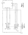
- the engine throttle is controlled by the electronic control module ("ECM"), as shown in Fig. 1.
- ECM 102 is a microprocessor that receives electronic inputs from sensors and switches, and it provides a reference voltage for some sensors, including throttle position sensor (“TPS”) 120.
- TPS 120 typically is a potentiometer that senses the position of the vehicle's accelerator pedal 130.
- the potentiometer of TPS 120 includes potentiometer 122, which provides a resistance, and wiper arm 124. Wiper arm 124 is in contact with and positioned along potentiometer 122 by pedal input 132 in accordance with the position of accelerator pedal 130. Accelerator pedal 130 is capable of both accelerating an engine and decelerating an engine to an idle state. Wiper arm 124 is connected to pedal 130 either by mechanical or electrical means. Potentiometer 122 is connected between lines 126,128, and wiper arm 124 is connected to line 125. Line 126 is referenced to ground. Lines 125, 126,128 are connected to ECM 102. TPS 120 is operated by pedal input 134 to determine position of pedal 130 from idle to full-throttle positions. Alternatively, TPS 120 may be implemented as an optical encoder, a variable magnetic inductance, a variable capacitance or a variable conductance.
- ECM 102 provides a five (5) volt potential to TPS 120 via line 128.
- the voltage drop apparent to ECM 102 depends on the position of accelerator pedal 130.
- the voltage is applied across potentiometer 122, and wiper arm 124 picks up the voltage drop (referred to hereinafter as the throttle position signal) and provides it via line 125 to ECM 102 as an input. Consequently, the throttle position signal indicates the position of accelerator pedal 130, and as the angle of pedal 130 changes, TPS 120 varies the throttle position signal to ECM 102.
- TPS 120 is often included as a part of TPS assembly 170 along with idle validation switch ("IVS") 140.
- IVS 140 indicates to ECM 102 when accelerator pedal 130 is or is not at the idle position.
- IVS 140 includes switch 142 and terminals 144, 146.
- Switch 142 is connected to line 152
- terminal 144 is connected to validation signal line 148
- terminal 146 is connected to validation signal line 150.
- Lines 148, 150, 152 are connected to ECM 102.
- IVS 140 is a two-position switch such that when switch 142 is in contact with terminal 144, IVS 140 indicates an idle position and when switch 142 and terminal 146 are closed, IVS 140 indicates an off-idle position.
- the function of IVS 140 is to provide a fail-safe in the event that a failure occurs in the throttle wiring or circuits. In such a case, ECM 102 causes the engine throttle to idle.
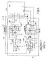
- Vehicle disable system 200 includes ECM 202, TPS 220 and IVS 240.
- TPS 220 includes throttle voltage supply line 230, ground line 226 and throttle position signal line 228.
- Throttle position signal line 228 includes lines 228a, 228b.
- switch mechanism 280 In the throttle's enabled state A, switch mechanism 280 enables throttle position signal line 228a to connect throttle position sensor 220 to ECM 202.
- switch mechanism 280 In the throttle's disabled state B, switch mechanism 280 enables throttle position signal line 228 to connect throttle position sensor 220 to idling device 286, and throttle position signal line 228b connects idling mechanism 286 to ECM 202.
- idling mechanism 228b includes a potentiometer.
- IVS 240 includes validation signal lines 248, 250 and ground line 252.
- Validation signal line 248 includes lines 248a, 248b.
- Switch mechanism 260 enables validation signal line 248a to be utilized by the vehicle disable system when the throttle is in its enabled state A, and switch mechanism 260 enables validation signal line 248b to be utilized by the disable system when the throttle is in its disabled state B.
- Validation signal line 248a connects IVS 240 to ECM 202
- validation signal line 248b connects IVS 240 to ground line 252.
- validation signal line 250 includes lines 250a, 250b.
- Switch mechanism 251 enables the vehicle disable system to use validation signal line 250a when the throttle is in its enabled state A, and switch 251 enables the vehicle disable system to use validation signal line 250b when the throttle is in its disabled state B.
- Validation signal line 250 a connects IVS 240 to ECM 202, and validation signal line 250b is open.
- the vehicle disable system of the present invention when the throttle is in its enabled state A, the vehicle disable system of the present invention enables TPS 220 to pass unaltered signals to ECM 202 via throttle position signal line 228a and enables IVS 240 to pass unaltered signals to ECM 202 on validation signal lines 248a, 250a.
- throttle position signal line 228 and validation signal line 248 are modified to resemble the idle state of accelerator pedal 232. In disabled state B, TPS 220 and IVS 240 are not able to pass unaltered signals to ECM 202.
- the throttle position signal passed on throttle position signal line 228 is intercepted by idling mechanism 286, and idling mechanism 286 generates and transmits an idle voltage to ECM 202 on throttle position signal line 228b.
- the validation signal passed on validation signal line 248 is routed to ground line 252 via validation signal line 248b, and the validation signal passed on validation signal line 250 is opened via validation signal line 250b.
- Fig. 3 illustrates vehicle disable system 300 when the throttle is disabled.
- Vehicle disable system 300 includes ECM 302, pedal 332, pedal input 334, throttle position sensor assembly 370 and security controller 390.
- Throttle position sensor assembly 370 includes TPS 320 and IVS 340.
- TPS 320 includes potentiometer 322 connected to line 326 and voltage supply line 328.
- ECM 302 provides a voltage potential, in the exemplary embodiment a +5VDC, via voltage supply line 328 to potentiometer 322, in the exemplary embodiment a three (3) kilohm potentiometer.
- Wiper arm 324 is in contact with potentiometer 322 and is connected to throttle position signal line 324.
- pedal 332 When pedal 332 is depressed, thereby enabling the throttle, wiper arm 324 sends a throttle position signal to ECM 302 via throttle position signal line 324 that may, in the exemplary embodiment, vary from +1V (idle) to +4V (full throttle).
- TPS 320 also includes relay 380.
- Relay 380 includes coil 381 that becomes energized upon receipt of a signal from security control unit 390 via override input signal line 392.
- Relay 380 includes switches 382, 384 and is shown in Fig. 3 in an energized state. In this energized state, switches 382, 384 are in a non-idle position. In a non-idle position, switch 382 connects throttle position signal line 324 to ECM 302 by maintaining a connection between first portion 324a and second portion 324b. Second portion 324b serves as an ECM input and is connected to ECM 302.
- switch 384 When switch 384 is in a non-idle position, it connects voltage supply line 328 to ECM 302 by maintaining a connection between first portion 328a and second portion 328b. Second portion 328b connects to ECM 302.
- relay's 380 functionality may be provided by analog circuitry, digital circuitry, and a microprocessor carrying out program instructions.
- IVS 340 includes terminal 344 connected to validation signal line 348, terminal 346 connected to validation signal line 350, and switch 342 connected to ground line 352.
- switch 342 When pedal 332 is depressed and the throttle is enabled, switch 342 is in communication with terminal 346.
- IVS 340 also includes relay 360, which has switches 362, 364, both of which are shown in a non-idle position.
- switch 362 When pedal 332 is depressed and switches 362, 364 are in a non-idle position, switch 362 connects validation signal line 348 to ECM 202 by maintaining a connection between first portion 348a and second portion 348b.
- switch 364 When in a non-idle position, switch 364 connects validation signal line 350 to ECM 302 by maintaining a connection between first portion 350a and second portion 350b.
- the function of relay 360 also may be provided by analog circuitry, digital circuitry, and a microprocessor carrying out program instructions.
- Fig. 4 the method of the present invention may be described as implemented in vehicle disable system 400, shown when a throttle is in a disabled state, or idle. If security control unit 490 applies a high voltage on override input line 492, the throttle will be it its enabled state. In order to force the throttle to idle, however, security control unit 490 applies a low voltage to relays 460, 480 via override input line 492. The low voltage provided on input line 492 de-energizes coils 461, 481 and enables switches 462, 464, 482, 484 to move to their idle positions. In moving to its idle position, switch 482 disconnects throttle position signal line 424 from ECM 402.
- Throttle position signal line first portion 424a is disconnected from throttle position signal line second portion 424b, and switch 482 connects ECM input 424b to alternative throttle position signal line 483. Therefore, the throttle position signal provided by wiper arm 424 to ECM 402 is no longer able to be transmitted to ECM 402.
- Switch 484 in its idle position, disconnects voltage supply line 428 from ECM 402 by disconnecting voltage supply line first portion 428a from second voltage supply line second portion 428b and connecting second portion 428b to alternative voltage supply line 486.
- Alternative voltage supply line 486 includes alternative potentiometer 487.
- Potentiometer 487 provides a two (2) resistor voltage divider, in the exemplary embodiment including 2.4K resistor 487a and 600K resistor 487b. The two (2) resistor voltage divider is used to provide the alternative voltage supply to ECM 402.
- Alternative throttle position signal line 483 is in contact with alternative potentiometer 487.
- alternative throttle position signal line 483 is provided with a voltage equal to V 1 R 2 /(R 1 + R 2 ), i.e., 5*600K/(3000K), or +1V; thus, providing an idle voltage to ECM 402 and forcing the throttle to an idle state in this exemplary embodiment.
- IVS 440 verifies to ECM 402 that the throttle is in an idle state.
- Switch 442 is in communication with terminal 444, which is connected to validation signal line 448.
- the same low voltage applied by security control unit 490 via override signal line 492 to effect the idle positions of switches 482, 484 of relay 480 also effects the idle positions of switches 462, 464.
- switch 462 disconnects validation signal line 448 from ECM 402 and connects validation signal line second portion 448b to ground line 452.
- Energized switch 464 disconnects validation signal line 450 from ECM 402 and connects second portion 450b to open line 465. IVS 440 thus appears to be in its idle state.
- a method and controller may be used to degrade and/or disable a throttle.
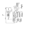
- Fig. 5 illustrates a block diagram of vehicle disable system 500 in which controller 510 of the present invention is implemented and provided with a pulse width modulated ("PWM") signal.
- PWM pulse width modulated
- the two primary types of throttle position signals are PWM signals and analog voltage from potentiometers. While the PWM signal is digital and only takes a value from a finite set of predetermined possibilities (e.g., 0V, 5V), the analog voltage has a continuously varying value.
- the PWM signal also has a range of 0% to 100% duty cycles. The duty cycle is proportional to the pedal position, as provided by pedal input 534.
- a throttle position signal having a 10% duty cycle is on for 10% of the period and off the other 90%.
- controller 510 is shown as the main telematics controller and may be any number of computing platforms or controllers, including, e.g., TruckPC, a commercial fleet management tool built upon an open architectural platform and powered by the Microsoft Windows CE® operating system (WINDOWS CE is a registered trademark of Microsoft Corporation of Redmond, Washington). Controller 510 may also be implemented as Onstar (ONSTAR is a registered trademark of General Motors Corporation of Detroit, Michigan), Lojack (LOJACK is a registered trademark of Lojack Corporation of Westwood Massachusetts), or other systems providing vehicle navigation functionality. Controller 510 includes processor 511 and memory 513, including random access memory and read only memory for the storage of data and program instructions, e.g., the instructions executed by controller 510 to control ILTC 520.
- WINDOWS CE is a registered trademark of Microsoft Corporation of Redmond, Washington
- Controller 510 may also be implemented as Onstar (ONSTAR is a registered trademark of General Motors Corporation of Detroit, Michigan), Lojack (LOJACK is a registered trademark of Lojack Corporation of Westwood Massachusetts), or
- Controller 510 also includes GPS receiver functionality. Accordingly, controller 510 may receive GPS signals and translate those signals into vehicle position information. Vehicle position information may include a vehicle's global positioning coordinates as determined by the position of controller 510. In order for controller 510 to determine in which zone the vehicle is positioned, controller 510 may transmit the vehicle's location information via wireless communication link 517 to control center 512 in the form of a location report. Control center 512 may then compare the location report with the vehicle's preprogrammed route information. It is also conceived that the vehicle's preprogrammed route information may be wirelessly transferred to controller 510, which may be programmed to compare the route information with its present location to determine in which zone the vehicle is located.
- controller 510 may include program instructions in memory 527 to be executed by processor 523 that enables controller 510 to appropriately interpret throttle position signals as they relate to the relevant predefined zones and appropriately command ILTC 520.
- the program instructions may be stored and executed using memory and processing devices located at control center 512 such that control center 512 can appropriately instruct ILTC 520.
- ILTC 520 includes processor 523 for carrying out the commands of controller 510, and processor 523 includes input capture timer port 525, timer 526 and memory 527.
- Fig. 5 will now be described in conjunction with Fig. 6 to explain an example of the degrade and disable functions of the present invention.
- ILTC 520 receives a pedal input 534 from vehicle pedal 532 in the form of a throttle position signal.
- ILTC 520 receives the signal via input port 425 (step 600).
- Zone levels may be defined by the user of the inventive system in order to provide a basis upon which the determination to degrade or disable the throttle may be made. While three (3) zone levels (i.e., a green, yellow and red) have been described supra in regards to the present invention, it is contemplated that many zone levels, or their functional equivalents, may be used.
- the "green" zone may have a broad scope of definitions depending on the needs of the entity implementing vehicle disable system 500. For example, as described above, a zone level may be defined to indicate a vehicle's geographic location. A zone level, however, may also be defined to indicate improper driver authentication.
- the driver of a vehicle may use biometric device 514 (e.g., facial or fingerprint recognition device) or other mechanism to authenticate the driver's identity before her use of a vehicle. If the authentication device indicates that the vehicle is being used by the wrong driver, a specified zone level may be defined that instructs the inventive system that the vehicle's throttle should be degraded or disabled. In yet another example, a zone level may be defined to indicate that a silent alarm has been triggered.
- the driver of a vehicle may also use key fob 516 or similar device during driver authentication to indicate that the driver is being hijacked. In such a case, the driver's use of the key fob could enable a silent alarm and a corresponding zone level may be defined that instructs the vehicle disable system to degrade or disable the vehicle's throttle.
- zone levels are used to indicate the geographic location of a vehicle.
- the "green” zone indicates the predefined route which a vehicle is expected to follow.
- the "yellow” zone indicates that the vehicle is either getting too close to a predetermined prohibited location or too far from a predetermined specified route, and the “red” zone indicates that the vehicle is either dangerously close to a predetermined prohibited location or extremely far from a predetermined specified route.
- controller 510 determines the vehicle's zone level, it transmits the zone level information to ILTC 520 over control line 515.
- ILTC 520 transmits the PWM signal to ECM 502 over signal line 521 (step 604). If the vehicle is in the "yellow” zone, input capture port 525 calculates the signal's duty cycle (step 606) and determines whether the PWM signal has a duty cycle greater or less than a predefined "limit” (step 608). If the PWM signal has a duty cycle less than the predefined limit (e.g., a 45% duty cycle when the predetermined limit is a 50% duty cycle), then ILTC 520 passes the signal to ECM 502 over signal lines 521, 521a (step 610).
- the predefined limit e.g., a 45% duty cycle when the predetermined limit is a 50% duty cycle
- timer 526 If port 525 calculates the PWM signal to be greater than the predefined limit (e.g., a 60% duty cycle), then timer 526 generates a signal with a duty cycle fixed at the predetermined limit (50%) (step 612) and passes the fixed signal to ECM 502 via signal lines 521, 521a (step 610). If the vehicle is in the "red" zone, timer 526 generates a signal with the predetermined idle duty cycle (e.g., a 10% duty cycle) (step 614) and passes the signal to ECM 502 on lines 521, 521b.
- the predefined limit e.g., a 60% duty cycle
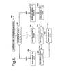
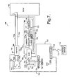
- Fig. 7 illustrates a block diagram of vehicle disable system 700 in which controller 770 of the present invention is implemented and provided with analog throttle position sensor signals.
- Fig. 7 will be described in conjunction with Fig. 8 to explain the method of the present invention.
- ILTC 770 receives a pedal input 734 from vehicle pedal 732 in the form of a throttle position signal.
- ILTC 770 receives the signal via input port 771 (step 800).
- ILTC 770 then polls controller 710 to determine in which zone the vehicle is positioned (step 802).
- Controller 710 transmits the requested vehicle position information to ILTC 770 over control line 715.
- ILTC 770 passes the signal over lines 717, 717a to switch 780, which switches the signal to ECM 702 over line 718 (step 804). If controller 710 determines that the vehicle is in the "yellow” zone, input port 771 determines whether the signal has a voltage less than a predefined limit (step 806). If the signal is determined to have a voltage less than the limit, ILTC 770 transmits the signal to switch 780 via signal lines 717, 717b. Switch 780 then switches the signal to ECM 702 via signal line 718 (step 808).
- ILTC 770 instructs signal generating device 728 to generate a voltage equal to the predefined limit (step 810), and this voltage is applied to signal line 717 and transmitted to switch 780, which switches the signal to ECM 702 (step 808).
- signal generating device 728 is an analog to digital converter. In other embodiments of the present invention, signal generating device 728 may be a potentiometer.
- controller 710 determines that the vehicle is in the "red” zone
- ILTC 770 instructs signal generating device 729 to generate a predetermined idle voltage (step 812), and this voltage is applied to signal line 717 and passed to ECM 702 (step 814).
- controller 710 may indicate to controller 710 that the throttle needs to be forced to idle.
- Controller 710 may include program instructions that, when executed, enable it to instruct ILTC 770 to force the throttle to idle. It is further conceived that ILTC 770 may receive feedback voltages from signal lines 748a, 750a via lines 735, 736, 737 to verify that no tampering has occurred with vehicle disable system 700.
Landscapes
- Engineering & Computer Science (AREA)
- Mechanical Engineering (AREA)
- Human Computer Interaction (AREA)
- Radar, Positioning & Navigation (AREA)
- Remote Sensing (AREA)
- Combined Controls Of Internal Combustion Engines (AREA)
- Control Of Throttle Valves Provided In The Intake System Or In The Exhaust System (AREA)
- Chairs Characterized By Structure (AREA)
- Steering Control In Accordance With Driving Conditions (AREA)
Applications Claiming Priority (2)
| Application Number | Priority Date | Filing Date | Title |
|---|---|---|---|
| US10/779,935 US7434649B2 (en) | 2004-02-17 | 2004-02-17 | Throttle disable method and system |
| US779935 | 2004-02-17 |
Publications (3)
| Publication Number | Publication Date |
|---|---|
| EP1577179A2 true EP1577179A2 (fr) | 2005-09-21 |
| EP1577179A3 EP1577179A3 (fr) | 2005-10-05 |
| EP1577179B1 EP1577179B1 (fr) | 2010-09-08 |
Family
ID=34838469
Family Applications (1)
| Application Number | Title | Priority Date | Filing Date |
|---|---|---|---|
| EP05075278A Active EP1577179B1 (fr) | 2004-02-17 | 2005-02-03 | Procédé et système de mise hors fonction de papillon |
Country Status (4)
| Country | Link |
|---|---|
| US (2) | US7434649B2 (fr) |
| EP (1) | EP1577179B1 (fr) |
| AT (1) | ATE480430T1 (fr) |
| DE (1) | DE602005023369D1 (fr) |
Cited By (1)
| Publication number | Priority date | Publication date | Assignee | Title |
|---|---|---|---|---|
| EP3159223A1 (fr) * | 2015-10-23 | 2017-04-26 | William Wei-Lun Tsai | Circuit et procédé de blocage d'accélérateur de véhicule |
Families Citing this family (12)
| Publication number | Priority date | Publication date | Assignee | Title |
|---|---|---|---|---|
| US7239235B2 (en) * | 2004-04-01 | 2007-07-03 | Williams Controls Industries, Inc. | Non-contact sensor idle validation switch |
| US20090027177A1 (en) * | 2007-07-28 | 2009-01-29 | David John Hodder | Processor Controlled Adaptive Safety System with Remote Shutdown |
| US9047494B1 (en) * | 2008-09-08 | 2015-06-02 | United Services Automobile Association | System and method for disabling and/or enabling a device |
| US20100082180A1 (en) * | 2008-10-01 | 2010-04-01 | Honeywell International Inc. | Errant vehicle countermeasures |
| US8983677B2 (en) * | 2008-10-01 | 2015-03-17 | Honeywell International Inc. | Acoustic fingerprinting of mechanical devices |
| EP2531711A2 (fr) * | 2010-02-05 | 2012-12-12 | Smart Throttle Technologies LLC | Système permettant de désactiver la réponse du papillon du moteur |
| US8897928B2 (en) * | 2011-09-30 | 2014-11-25 | Omnitracs, Llc | Systems for and methods of engine derating |
| US9304515B2 (en) | 2014-04-24 | 2016-04-05 | Lenovo Enterprise Solutions (Singapore) Pte. Ltd. | Regional operation modes for autonomous vehicles |
| US9349284B2 (en) | 2014-04-24 | 2016-05-24 | International Business Machines Corporation | Regional driving trend modification using autonomous vehicles |
| US10208693B2 (en) * | 2015-10-28 | 2019-02-19 | Ford Global Technologies, Llc | Method and system to mitigate throttle degradation |
| DE102015223867B3 (de) * | 2015-12-01 | 2017-04-06 | Robert Bosch Gmbh | Verfahren zur Beeinflussung der Inbewegungsetzbarkeit eines Kraftfahrzeugs, Wegfahrsperrvorrichtung und Mittel zur Implementierung des Verfahrens |
| EP3445602A4 (fr) | 2016-04-19 | 2020-06-10 | Magtec Products, Inc. | Système et procédé de commande de papillon |
Citations (4)
| Publication number | Priority date | Publication date | Assignee | Title |
|---|---|---|---|---|
| US5445126A (en) * | 1994-06-24 | 1995-08-29 | Eaton Corporation | Accelerator pedal calibration and fault detection |
| US5828297A (en) * | 1997-06-25 | 1998-10-27 | Cummins Engine Company, Inc. | Vehicle anti-theft system |
| WO2003044632A2 (fr) * | 2001-11-19 | 2003-05-30 | Volvo Trucks North America Inc. | Systeme de gestion d'itineraires |
| US20030169161A1 (en) * | 2002-03-07 | 2003-09-11 | International Business Machines Corporation | Vehicle security system |
Family Cites Families (16)
| Publication number | Priority date | Publication date | Assignee | Title |
|---|---|---|---|---|
| US4505169A (en) * | 1975-09-25 | 1985-03-19 | Ganoung David P | Apparatus using a continuously variable transmission to improve fuel economy |
| US4300205A (en) * | 1980-04-07 | 1981-11-10 | Acf Industries, Inc. | Automative engine simulating apparatus |
| US4638224A (en) * | 1984-08-29 | 1987-01-20 | Eaton Corporation | Mechanically shifted position senor for self-synchronous machines |
| US4665319A (en) * | 1985-03-21 | 1987-05-12 | General Electric Company | Self-propelled traction vehicle with low fuel consumption while idling |
| US5224044A (en) * | 1988-02-05 | 1993-06-29 | Nissan Motor Company, Limited | System for controlling driving condition of automotive device associated with vehicle slip control system |
| US5255192A (en) * | 1990-05-18 | 1993-10-19 | Mitsubishi Jidosha Kogyo Kabushiki Kaisha | Output control apparatus for vehicle |
| US5321980A (en) * | 1991-05-10 | 1994-06-21 | Williams Controls, Inc. | Integrated throttle position sensor with independent position validation sensor |
| JP3104512B2 (ja) * | 1993-12-28 | 2000-10-30 | 日産自動車株式会社 | 内燃機関のスロットル制御装置 |
| GB9402729D0 (en) * | 1994-02-12 | 1994-04-06 | Automotive Products Plc | Clutch control system |
| US5957991A (en) * | 1996-04-15 | 1999-09-28 | Nissan Motor Co., Ltd. | Vehicle drive torque controller |
| KR100318836B1 (ko) * | 1996-08-28 | 2002-02-19 | 나까무라히로까즈 | 기통내분사내연기관의제어장치 |
| US6060981A (en) * | 1999-04-23 | 2000-05-09 | Caterpillar Inc. | Vehicle security system for unattended idle operations |
| US6701897B2 (en) * | 2001-02-16 | 2004-03-09 | Optimum Power Technology | Engine fuel delivery management system |
| US6619258B2 (en) * | 2002-01-15 | 2003-09-16 | Delphi Technologies, Inc. | System for controllably disabling cylinders in an internal combustion engine |
| JP4191968B2 (ja) * | 2002-08-27 | 2008-12-03 | トヨタ自動車株式会社 | 車両用駆動制御装置 |
| US6931315B2 (en) * | 2002-12-02 | 2005-08-16 | Toyota Jidosha Kabushiki Kaisha | Shift control apparatus and shift control method for a vehicular automatic transmission |
-
2004
- 2004-02-17 US US10/779,935 patent/US7434649B2/en active Active
-
2005
- 2005-02-03 DE DE602005023369T patent/DE602005023369D1/de active Active
- 2005-02-03 EP EP05075278A patent/EP1577179B1/fr active Active
- 2005-02-03 AT AT05075278T patent/ATE480430T1/de not_active IP Right Cessation
-
2008
- 2008-08-26 US US12/229,712 patent/US7699133B2/en not_active Expired - Lifetime
Patent Citations (4)
| Publication number | Priority date | Publication date | Assignee | Title |
|---|---|---|---|---|
| US5445126A (en) * | 1994-06-24 | 1995-08-29 | Eaton Corporation | Accelerator pedal calibration and fault detection |
| US5828297A (en) * | 1997-06-25 | 1998-10-27 | Cummins Engine Company, Inc. | Vehicle anti-theft system |
| WO2003044632A2 (fr) * | 2001-11-19 | 2003-05-30 | Volvo Trucks North America Inc. | Systeme de gestion d'itineraires |
| US20030169161A1 (en) * | 2002-03-07 | 2003-09-11 | International Business Machines Corporation | Vehicle security system |
Cited By (1)
| Publication number | Priority date | Publication date | Assignee | Title |
|---|---|---|---|---|
| EP3159223A1 (fr) * | 2015-10-23 | 2017-04-26 | William Wei-Lun Tsai | Circuit et procédé de blocage d'accélérateur de véhicule |
Also Published As
| Publication number | Publication date |
|---|---|
| ATE480430T1 (de) | 2010-09-15 |
| EP1577179B1 (fr) | 2010-09-08 |
| US7699133B2 (en) | 2010-04-20 |
| DE602005023369D1 (de) | 2010-10-21 |
| US20080314673A1 (en) | 2008-12-25 |
| US7434649B2 (en) | 2008-10-14 |
| US20050178602A1 (en) | 2005-08-18 |
| EP1577179A3 (fr) | 2005-10-05 |
Similar Documents
| Publication | Publication Date | Title |
|---|---|---|
| EP1577179B1 (fr) | Procédé et système de mise hors fonction de papillon | |
| CN112026521B (zh) | 车辆系统和车辆控制系统 | |
| US6060981A (en) | Vehicle security system for unattended idle operations | |
| US9002569B2 (en) | Vehicle shut-down functionality for PEPS-equipped vehicles | |
| US9014941B2 (en) | System and method for validating adaptive cruise control operations | |
| US20120245763A1 (en) | Drunk driving prevention system and external server used for the same | |
| US20090211831A1 (en) | Shift range switching control system and method for automatic transmission of vehicle | |
| US20090160379A1 (en) | Method for controlling a vehicle drive unit | |
| CN105620463B (zh) | 车辆控制系统和使用车辆控制系统的方法 | |
| US8290680B2 (en) | Onboard controller system | |
| KR100394654B1 (ko) | 자동차용 전자 스로틀 시스템의 림프 홈 제어방법 | |
| CN109177919B (zh) | 车辆防盗控制系统及车辆防盗控制方法 | |
| US20070129210A1 (en) | Vehicle control system and method | |
| EP0385813B1 (fr) | Système de commande à apprentissage pour papillon de moteur à combustion interne | |
| US6445083B2 (en) | Method and device for controlling a power adjustment means of a vehicle engine | |
| JP7544016B2 (ja) | 駆動力制御装置 | |
| US20050029869A1 (en) | Controlled vehicle shutdown system | |
| JPH11148406A (ja) | エンジンのスロットル弁制御装置 | |
| US7080705B2 (en) | Apparatus and method for data communication | |
| US9657668B2 (en) | Injector driver and operating method thereof | |
| CN115158451B (zh) | 控制装置、转向系统、车辆和转向控制方法 | |
| US11325562B1 (en) | Wire management module for a vehicle | |
| US11724711B2 (en) | Vehicle idling stop control method and vehicle idling stop control device | |
| US20210291848A1 (en) | Electric power supply apparatus and vehicle | |
| WO2016079617A1 (fr) | Dispositif et procédé permettant le verrouillage électronique d'une pédale de véhicules équipés d'un système de conduite à commande électrique |
Legal Events
| Date | Code | Title | Description |
|---|---|---|---|
| PUAI | Public reference made under article 153(3) epc to a published international application that has entered the european phase |
Free format text: ORIGINAL CODE: 0009012 |
|
| PUAL | Search report despatched |
Free format text: ORIGINAL CODE: 0009013 |
|
| AK | Designated contracting states |
Kind code of ref document: A2 Designated state(s): AT BE BG CH CY CZ DE DK EE ES FI FR GB GR HU IE IS IT LI LT LU MC NL PL PT RO SE SI SK TR |
|
| AX | Request for extension of the european patent |
Extension state: AL BA HR LV MK YU |
|
| AK | Designated contracting states |
Kind code of ref document: A3 Designated state(s): AT BE BG CH CY CZ DE DK EE ES FI FR GB GR HU IE IS IT LI LT LU MC NL PL PT RO SE SI SK TR |
|
| AX | Request for extension of the european patent |
Extension state: AL BA HR LV MK YU |
|
| 17P | Request for examination filed |
Effective date: 20060405 |
|
| AKX | Designation fees paid |
Designated state(s): AT BE BG CH CY CZ DE DK EE ES FI FR GB GR HU IE IS IT LI LT LU MC NL PL PT RO SE SI SK TR |
|
| 17Q | First examination report despatched |
Effective date: 20060628 |
|
| GRAP | Despatch of communication of intention to grant a patent |
Free format text: ORIGINAL CODE: EPIDOSNIGR1 |
|
| GRAS | Grant fee paid |
Free format text: ORIGINAL CODE: EPIDOSNIGR3 |
|
| GRAA | (expected) grant |
Free format text: ORIGINAL CODE: 0009210 |
|
| AK | Designated contracting states |
Kind code of ref document: B1 Designated state(s): AT BE BG CH CY CZ DE DK EE ES FI FR GB GR HU IE IS IT LI LT LU MC NL PL PT RO SE SI SK TR |
|
| REG | Reference to a national code |
Ref country code: GB Ref legal event code: FG4D |
|
| REG | Reference to a national code |
Ref country code: CH Ref legal event code: EP |
|
| REG | Reference to a national code |
Ref country code: IE Ref legal event code: FG4D |
|
| REF | Corresponds to: |
Ref document number: 602005023369 Country of ref document: DE Date of ref document: 20101021 Kind code of ref document: P |
|
| REG | Reference to a national code |
Ref country code: NL Ref legal event code: VDEP Effective date: 20100908 |
|
| PG25 | Lapsed in a contracting state [announced via postgrant information from national office to epo] |
Ref country code: FI Free format text: LAPSE BECAUSE OF FAILURE TO SUBMIT A TRANSLATION OF THE DESCRIPTION OR TO PAY THE FEE WITHIN THE PRESCRIBED TIME-LIMIT Effective date: 20100908 Ref country code: AT Free format text: LAPSE BECAUSE OF FAILURE TO SUBMIT A TRANSLATION OF THE DESCRIPTION OR TO PAY THE FEE WITHIN THE PRESCRIBED TIME-LIMIT Effective date: 20100908 Ref country code: LT Free format text: LAPSE BECAUSE OF FAILURE TO SUBMIT A TRANSLATION OF THE DESCRIPTION OR TO PAY THE FEE WITHIN THE PRESCRIBED TIME-LIMIT Effective date: 20100908 |
|
| LTIE | Lt: invalidation of european patent or patent extension |
Effective date: 20100908 |
|
| PG25 | Lapsed in a contracting state [announced via postgrant information from national office to epo] |
Ref country code: SI Free format text: LAPSE BECAUSE OF FAILURE TO SUBMIT A TRANSLATION OF THE DESCRIPTION OR TO PAY THE FEE WITHIN THE PRESCRIBED TIME-LIMIT Effective date: 20100908 Ref country code: PL Free format text: LAPSE BECAUSE OF FAILURE TO SUBMIT A TRANSLATION OF THE DESCRIPTION OR TO PAY THE FEE WITHIN THE PRESCRIBED TIME-LIMIT Effective date: 20100908 Ref country code: CY Free format text: LAPSE BECAUSE OF FAILURE TO SUBMIT A TRANSLATION OF THE DESCRIPTION OR TO PAY THE FEE WITHIN THE PRESCRIBED TIME-LIMIT Effective date: 20100908 |
|
| PG25 | Lapsed in a contracting state [announced via postgrant information from national office to epo] |
Ref country code: GR Free format text: LAPSE BECAUSE OF FAILURE TO SUBMIT A TRANSLATION OF THE DESCRIPTION OR TO PAY THE FEE WITHIN THE PRESCRIBED TIME-LIMIT Effective date: 20101209 Ref country code: SE Free format text: LAPSE BECAUSE OF FAILURE TO SUBMIT A TRANSLATION OF THE DESCRIPTION OR TO PAY THE FEE WITHIN THE PRESCRIBED TIME-LIMIT Effective date: 20100908 Ref country code: NL Free format text: LAPSE BECAUSE OF FAILURE TO SUBMIT A TRANSLATION OF THE DESCRIPTION OR TO PAY THE FEE WITHIN THE PRESCRIBED TIME-LIMIT Effective date: 20100908 |
|
| PG25 | Lapsed in a contracting state [announced via postgrant information from national office to epo] |
Ref country code: RO Free format text: LAPSE BECAUSE OF FAILURE TO SUBMIT A TRANSLATION OF THE DESCRIPTION OR TO PAY THE FEE WITHIN THE PRESCRIBED TIME-LIMIT Effective date: 20100908 Ref country code: CZ Free format text: LAPSE BECAUSE OF FAILURE TO SUBMIT A TRANSLATION OF THE DESCRIPTION OR TO PAY THE FEE WITHIN THE PRESCRIBED TIME-LIMIT Effective date: 20100908 Ref country code: EE Free format text: LAPSE BECAUSE OF FAILURE TO SUBMIT A TRANSLATION OF THE DESCRIPTION OR TO PAY THE FEE WITHIN THE PRESCRIBED TIME-LIMIT Effective date: 20100908 Ref country code: SK Free format text: LAPSE BECAUSE OF FAILURE TO SUBMIT A TRANSLATION OF THE DESCRIPTION OR TO PAY THE FEE WITHIN THE PRESCRIBED TIME-LIMIT Effective date: 20100908 Ref country code: IT Free format text: LAPSE BECAUSE OF FAILURE TO SUBMIT A TRANSLATION OF THE DESCRIPTION OR TO PAY THE FEE WITHIN THE PRESCRIBED TIME-LIMIT Effective date: 20100908 Ref country code: IS Free format text: LAPSE BECAUSE OF FAILURE TO SUBMIT A TRANSLATION OF THE DESCRIPTION OR TO PAY THE FEE WITHIN THE PRESCRIBED TIME-LIMIT Effective date: 20110108 Ref country code: PT Free format text: LAPSE BECAUSE OF FAILURE TO SUBMIT A TRANSLATION OF THE DESCRIPTION OR TO PAY THE FEE WITHIN THE PRESCRIBED TIME-LIMIT Effective date: 20110110 |
|
| PG25 | Lapsed in a contracting state [announced via postgrant information from national office to epo] |
Ref country code: ES Free format text: LAPSE BECAUSE OF FAILURE TO SUBMIT A TRANSLATION OF THE DESCRIPTION OR TO PAY THE FEE WITHIN THE PRESCRIBED TIME-LIMIT Effective date: 20101219 Ref country code: BE Free format text: LAPSE BECAUSE OF FAILURE TO SUBMIT A TRANSLATION OF THE DESCRIPTION OR TO PAY THE FEE WITHIN THE PRESCRIBED TIME-LIMIT Effective date: 20100908 |
|
| PLBE | No opposition filed within time limit |
Free format text: ORIGINAL CODE: 0009261 |
|
| STAA | Information on the status of an ep patent application or granted ep patent |
Free format text: STATUS: NO OPPOSITION FILED WITHIN TIME LIMIT |
|
| 26N | No opposition filed |
Effective date: 20110609 |
|
| PG25 | Lapsed in a contracting state [announced via postgrant information from national office to epo] |
Ref country code: DK Free format text: LAPSE BECAUSE OF FAILURE TO SUBMIT A TRANSLATION OF THE DESCRIPTION OR TO PAY THE FEE WITHIN THE PRESCRIBED TIME-LIMIT Effective date: 20100908 |
|
| PG25 | Lapsed in a contracting state [announced via postgrant information from national office to epo] |
Ref country code: MC Free format text: LAPSE BECAUSE OF NON-PAYMENT OF DUE FEES Effective date: 20110228 |
|
| REG | Reference to a national code |
Ref country code: CH Ref legal event code: PL |
|
| REG | Reference to a national code |
Ref country code: DE Ref legal event code: R097 Ref document number: 602005023369 Country of ref document: DE Effective date: 20110609 |
|
| PG25 | Lapsed in a contracting state [announced via postgrant information from national office to epo] |
Ref country code: CH Free format text: LAPSE BECAUSE OF NON-PAYMENT OF DUE FEES Effective date: 20110228 Ref country code: LI Free format text: LAPSE BECAUSE OF NON-PAYMENT OF DUE FEES Effective date: 20110228 |
|
| REG | Reference to a national code |
Ref country code: IE Ref legal event code: MM4A |
|
| PG25 | Lapsed in a contracting state [announced via postgrant information from national office to epo] |
Ref country code: IE Free format text: LAPSE BECAUSE OF NON-PAYMENT OF DUE FEES Effective date: 20110203 |
|
| PG25 | Lapsed in a contracting state [announced via postgrant information from national office to epo] |
Ref country code: LU Free format text: LAPSE BECAUSE OF NON-PAYMENT OF DUE FEES Effective date: 20110203 |
|
| PG25 | Lapsed in a contracting state [announced via postgrant information from national office to epo] |
Ref country code: BG Free format text: LAPSE BECAUSE OF FAILURE TO SUBMIT A TRANSLATION OF THE DESCRIPTION OR TO PAY THE FEE WITHIN THE PRESCRIBED TIME-LIMIT Effective date: 20101208 Ref country code: TR Free format text: LAPSE BECAUSE OF FAILURE TO SUBMIT A TRANSLATION OF THE DESCRIPTION OR TO PAY THE FEE WITHIN THE PRESCRIBED TIME-LIMIT Effective date: 20100908 |
|
| PG25 | Lapsed in a contracting state [announced via postgrant information from national office to epo] |
Ref country code: HU Free format text: LAPSE BECAUSE OF FAILURE TO SUBMIT A TRANSLATION OF THE DESCRIPTION OR TO PAY THE FEE WITHIN THE PRESCRIBED TIME-LIMIT Effective date: 20100908 |
|
| REG | Reference to a national code |
Ref country code: FR Ref legal event code: PLFP Year of fee payment: 12 |
|
| REG | Reference to a national code |
Ref country code: FR Ref legal event code: PLFP Year of fee payment: 13 |
|
| REG | Reference to a national code |
Ref country code: FR Ref legal event code: PLFP Year of fee payment: 14 |
|
| REG | Reference to a national code |
Ref country code: DE Ref legal event code: R082 Ref document number: 602005023369 Country of ref document: DE Representative=s name: MANITZ FINSTERWALD PATENT- UND RECHTSANWALTSPA, DE Ref country code: DE Ref legal event code: R081 Ref document number: 602005023369 Country of ref document: DE Owner name: DELPHI TECHNOLOGIES IP LIMITED, BB Free format text: FORMER OWNER: DELPHI TECHNOLOGIES, INC., TROY, MICH., US |
|
| REG | Reference to a national code |
Ref country code: GB Ref legal event code: 732E Free format text: REGISTERED BETWEEN 20190214 AND 20190221 |
|
| P01 | Opt-out of the competence of the unified patent court (upc) registered |
Effective date: 20230327 |
|
| PGFP | Annual fee paid to national office [announced via postgrant information from national office to epo] |
Ref country code: DE Payment date: 20240109 Year of fee payment: 20 Ref country code: GB Payment date: 20240111 Year of fee payment: 20 |
|
| PGFP | Annual fee paid to national office [announced via postgrant information from national office to epo] |
Ref country code: FR Payment date: 20240108 Year of fee payment: 20 |