EP1577172B1 - Airbag device - Google Patents
Airbag device Download PDFInfo
- Publication number
- EP1577172B1 EP1577172B1 EP05090062A EP05090062A EP1577172B1 EP 1577172 B1 EP1577172 B1 EP 1577172B1 EP 05090062 A EP05090062 A EP 05090062A EP 05090062 A EP05090062 A EP 05090062A EP 1577172 B1 EP1577172 B1 EP 1577172B1
- Authority
- EP
- European Patent Office
- Prior art keywords
- airbag
- bag
- vehicle
- chambers
- occupant
- Prior art date
- Legal status (The legal status is an assumption and is not a legal conclusion. Google has not performed a legal analysis and makes no representation as to the accuracy of the status listed.)
- Expired - Lifetime
Links
- 239000004744 fabric Substances 0.000 claims description 10
- 238000009958 sewing Methods 0.000 description 58
- XUIMIQQOPSSXEZ-UHFFFAOYSA-N Silicon Chemical compound [Si] XUIMIQQOPSSXEZ-UHFFFAOYSA-N 0.000 description 18
- 229910052710 silicon Inorganic materials 0.000 description 18
- 239000010703 silicon Substances 0.000 description 18
- 230000035939 shock Effects 0.000 description 9
- 230000003247 decreasing effect Effects 0.000 description 8
- 238000005452 bending Methods 0.000 description 7
- 238000010276 construction Methods 0.000 description 5
- 230000000694 effects Effects 0.000 description 3
- 238000000034 method Methods 0.000 description 3
- 230000007704 transition Effects 0.000 description 3
- 238000013459 approach Methods 0.000 description 2
- 238000005336 cracking Methods 0.000 description 2
- 230000007423 decrease Effects 0.000 description 2
- 230000000994 depressogenic effect Effects 0.000 description 2
- 229920001296 polysiloxane Polymers 0.000 description 2
- 239000002210 silicon-based material Substances 0.000 description 2
- 239000006096 absorbing agent Substances 0.000 description 1
- 230000015572 biosynthetic process Effects 0.000 description 1
- 230000000052 comparative effect Effects 0.000 description 1
- 210000003127 knee Anatomy 0.000 description 1
- 238000004806 packaging method and process Methods 0.000 description 1
- 230000035699 permeability Effects 0.000 description 1
- 230000008569 process Effects 0.000 description 1
- 230000003313 weakening effect Effects 0.000 description 1
Images


Classifications
-
- B—PERFORMING OPERATIONS; TRANSPORTING
- B60—VEHICLES IN GENERAL
- B60R—VEHICLES, VEHICLE FITTINGS, OR VEHICLE PARTS, NOT OTHERWISE PROVIDED FOR
- B60R21/00—Arrangements or fittings on vehicles for protecting or preventing injuries to occupants or pedestrians in case of accidents or other traffic risks
- B60R21/02—Occupant safety arrangements or fittings, e.g. crash pads
- B60R21/16—Inflatable occupant restraints or confinements designed to inflate upon impact or impending impact, e.g. air bags
- B60R21/23—Inflatable members
- B60R21/231—Inflatable members characterised by their shape, construction or spatial configuration
- B60R21/233—Inflatable members characterised by their shape, construction or spatial configuration comprising a plurality of individual compartments; comprising two or more bag-like members, one within the other
-
- B—PERFORMING OPERATIONS; TRANSPORTING
- B60—VEHICLES IN GENERAL
- B60R—VEHICLES, VEHICLE FITTINGS, OR VEHICLE PARTS, NOT OTHERWISE PROVIDED FOR
- B60R21/00—Arrangements or fittings on vehicles for protecting or preventing injuries to occupants or pedestrians in case of accidents or other traffic risks
- B60R21/02—Occupant safety arrangements or fittings, e.g. crash pads
- B60R21/16—Inflatable occupant restraints or confinements designed to inflate upon impact or impending impact, e.g. air bags
- B60R21/23—Inflatable members
- B60R21/231—Inflatable members characterised by their shape, construction or spatial configuration
- B60R21/232—Curtain-type airbags deploying mainly in a vertical direction from their top edge
-
- B—PERFORMING OPERATIONS; TRANSPORTING
- B60—VEHICLES IN GENERAL
- B60R—VEHICLES, VEHICLE FITTINGS, OR VEHICLE PARTS, NOT OTHERWISE PROVIDED FOR
- B60R21/00—Arrangements or fittings on vehicles for protecting or preventing injuries to occupants or pedestrians in case of accidents or other traffic risks
- B60R21/02—Occupant safety arrangements or fittings, e.g. crash pads
- B60R21/16—Inflatable occupant restraints or confinements designed to inflate upon impact or impending impact, e.g. air bags
- B60R21/23—Inflatable members
- B60R21/231—Inflatable members characterised by their shape, construction or spatial configuration
- B60R21/2334—Expansion control features
- B60R21/2338—Tethers
-
- B—PERFORMING OPERATIONS; TRANSPORTING
- B60—VEHICLES IN GENERAL
- B60R—VEHICLES, VEHICLE FITTINGS, OR VEHICLE PARTS, NOT OTHERWISE PROVIDED FOR
- B60R21/00—Arrangements or fittings on vehicles for protecting or preventing injuries to occupants or pedestrians in case of accidents or other traffic risks
- B60R21/34—Protecting non-occupants of a vehicle, e.g. pedestrians
- B60R21/36—Protecting non-occupants of a vehicle, e.g. pedestrians using airbags
-
- B—PERFORMING OPERATIONS; TRANSPORTING
- B60—VEHICLES IN GENERAL
- B60R—VEHICLES, VEHICLE FITTINGS, OR VEHICLE PARTS, NOT OTHERWISE PROVIDED FOR
- B60R21/00—Arrangements or fittings on vehicles for protecting or preventing injuries to occupants or pedestrians in case of accidents or other traffic risks
- B60R21/02—Occupant safety arrangements or fittings, e.g. crash pads
- B60R21/16—Inflatable occupant restraints or confinements designed to inflate upon impact or impending impact, e.g. air bags
- B60R21/23—Inflatable members
- B60R21/231—Inflatable members characterised by their shape, construction or spatial configuration
- B60R2021/23169—Inflatable members characterised by their shape, construction or spatial configuration specially adapted for knee protection
-
- B—PERFORMING OPERATIONS; TRANSPORTING
- B60—VEHICLES IN GENERAL
- B60R—VEHICLES, VEHICLE FITTINGS, OR VEHICLE PARTS, NOT OTHERWISE PROVIDED FOR
- B60R21/00—Arrangements or fittings on vehicles for protecting or preventing injuries to occupants or pedestrians in case of accidents or other traffic risks
- B60R21/02—Occupant safety arrangements or fittings, e.g. crash pads
- B60R21/16—Inflatable occupant restraints or confinements designed to inflate upon impact or impending impact, e.g. air bags
- B60R21/23—Inflatable members
- B60R21/231—Inflatable members characterised by their shape, construction or spatial configuration
- B60R2021/23192—Roof bags, i.e. protecting the occupant in a roll-over situation
-
- B—PERFORMING OPERATIONS; TRANSPORTING
- B60—VEHICLES IN GENERAL
- B60R—VEHICLES, VEHICLE FITTINGS, OR VEHICLE PARTS, NOT OTHERWISE PROVIDED FOR
- B60R21/00—Arrangements or fittings on vehicles for protecting or preventing injuries to occupants or pedestrians in case of accidents or other traffic risks
- B60R21/02—Occupant safety arrangements or fittings, e.g. crash pads
- B60R21/16—Inflatable occupant restraints or confinements designed to inflate upon impact or impending impact, e.g. air bags
- B60R21/23—Inflatable members
- B60R21/231—Inflatable members characterised by their shape, construction or spatial configuration
- B60R21/233—Inflatable members characterised by their shape, construction or spatial configuration comprising a plurality of individual compartments; comprising two or more bag-like members, one within the other
- B60R2021/23316—Inner seams, e.g. creating separate compartments or used as tethering means
-
- B—PERFORMING OPERATIONS; TRANSPORTING
- B60—VEHICLES IN GENERAL
- B60R—VEHICLES, VEHICLE FITTINGS, OR VEHICLE PARTS, NOT OTHERWISE PROVIDED FOR
- B60R21/00—Arrangements or fittings on vehicles for protecting or preventing injuries to occupants or pedestrians in case of accidents or other traffic risks
- B60R21/02—Occupant safety arrangements or fittings, e.g. crash pads
- B60R21/16—Inflatable occupant restraints or confinements designed to inflate upon impact or impending impact, e.g. air bags
- B60R21/23—Inflatable members
- B60R21/231—Inflatable members characterised by their shape, construction or spatial configuration
- B60R21/233—Inflatable members characterised by their shape, construction or spatial configuration comprising a plurality of individual compartments; comprising two or more bag-like members, one within the other
- B60R2021/23324—Inner walls crating separate compartments, e.g. communicating with vents
-
- B—PERFORMING OPERATIONS; TRANSPORTING
- B60—VEHICLES IN GENERAL
- B60R—VEHICLES, VEHICLE FITTINGS, OR VEHICLE PARTS, NOT OTHERWISE PROVIDED FOR
- B60R21/00—Arrangements or fittings on vehicles for protecting or preventing injuries to occupants or pedestrians in case of accidents or other traffic risks
- B60R21/02—Occupant safety arrangements or fittings, e.g. crash pads
- B60R21/16—Inflatable occupant restraints or confinements designed to inflate upon impact or impending impact, e.g. air bags
- B60R21/23—Inflatable members
- B60R21/231—Inflatable members characterised by their shape, construction or spatial configuration
- B60R21/2334—Expansion control features
- B60R21/2338—Tethers
- B60R2021/23382—Internal tether means
-
- B—PERFORMING OPERATIONS; TRANSPORTING
- B60—VEHICLES IN GENERAL
- B60R—VEHICLES, VEHICLE FITTINGS, OR VEHICLE PARTS, NOT OTHERWISE PROVIDED FOR
- B60R21/00—Arrangements or fittings on vehicles for protecting or preventing injuries to occupants or pedestrians in case of accidents or other traffic risks
- B60R21/02—Occupant safety arrangements or fittings, e.g. crash pads
- B60R21/16—Inflatable occupant restraints or confinements designed to inflate upon impact or impending impact, e.g. air bags
- B60R21/23—Inflatable members
- B60R21/231—Inflatable members characterised by their shape, construction or spatial configuration
- B60R21/2334—Expansion control features
- B60R21/2338—Tethers
- B60R2021/23386—External tether means
-
- B—PERFORMING OPERATIONS; TRANSPORTING
- B60—VEHICLES IN GENERAL
- B60R—VEHICLES, VEHICLE FITTINGS, OR VEHICLE PARTS, NOT OTHERWISE PROVIDED FOR
- B60R21/00—Arrangements or fittings on vehicles for protecting or preventing injuries to occupants or pedestrians in case of accidents or other traffic risks
- B60R21/02—Occupant safety arrangements or fittings, e.g. crash pads
- B60R21/06—Safety nets, transparent sheets, curtains, or the like, e.g. between occupants and glass
- B60R21/08—Safety nets, transparent sheets, curtains, or the like, e.g. between occupants and glass automatically movable from an inoperative to an operative position, e.g. in a collision
-
- B—PERFORMING OPERATIONS; TRANSPORTING
- B60—VEHICLES IN GENERAL
- B60R—VEHICLES, VEHICLE FITTINGS, OR VEHICLE PARTS, NOT OTHERWISE PROVIDED FOR
- B60R21/00—Arrangements or fittings on vehicles for protecting or preventing injuries to occupants or pedestrians in case of accidents or other traffic risks
- B60R21/02—Occupant safety arrangements or fittings, e.g. crash pads
- B60R21/16—Inflatable occupant restraints or confinements designed to inflate upon impact or impending impact, e.g. air bags
- B60R21/23—Inflatable members
- B60R21/231—Inflatable members characterised by their shape, construction or spatial configuration
- B60R21/2334—Expansion control features
- B60R21/2342—Tear seams
Definitions
- the present invention relates to an airbag for protecting the head of a vehicle occupant, and more particularly, to a head protection airbag which is constructed so as to be deployed along a side door pillar and the like upon a side impact or a roll-over of a vehicle. Also, the present invention relates to a head protection airbag device having the head protection airbag.
- an airbag for protecting the head of a vehicle occupant is installed adjacent to a corner of a vehicle interior where a roof panel and a side panel are joined to each other, and is constructed so as to be deployed along a side door window and the like when gas is introduced therein from an inflator through a gas inlet.
- WO 97/06987 discloses a side airbag according to the preamble of claim 1, which is deployed on the side of a vehicle occupant.
- a longitudinal intermediate portion of a bag is constricted by a seam which extends in a transverse direction (a lengthwise direction of a vehicle body: this also applies to the following description), so that the bag is divided into an upper portion and a lower portion.
- a panel is positioned along a portion of the airbag which faces the vehicle occupant.
- the upper and lower portions of the panel are respectively connected to the upper and lower portions of the bag.
- the panel When the bag is inflated, the panel is tightly stretched. Then, as the shoulder of the occupant comes into contact with the bag, the panel pulls the upper portion of the bag downward. As such, the upper portion of the bag is pulled toward the vehicle occupant to protect the head of the vehicle occupant.
- Japanese Unexamined Patent Application Publication No. 2003-72500 discloses an airbag for protecting the head of a vehicle occupant.
- supporting fabric is positioned on the sides of a bag which faces both a vehicle occupant and a vehicle body.
- the upper and lower edges of the supporting fabric are coupled to the upper and lower edges of the bag.
- the supporting fabric contributes to the protection of the occupant's head.
- the thickness of a connection member of the airbag needs to be increased, which consequently increases the size of the airbag.
- US 5 636 862 A discloses an airbag assembly comprising an airbag and a tether having a first end connected to the airbag and a second end connected to the vehicle.
- the invention relates to an airbag device.
- the airbag device comprises an airbag having first and second side surfaces and upper and lower ends; a member connecting the upper and lower ends of the airbag; wherein the airbag is configured to inflate into a position wherein an enveloped space is defined by the first side surface and a plane containing the connecting member.
- the airbag includes an intermediate portion and comprises a first panel and a second panel connected to form a chamber,
- the ratio of the volume of the enveloped space over the volume of the inflated airbag may be greater than approximately 1.0.
- an occupant safety system comprising an airbag having first and second side surfaces and upper and lower ends, a member connecting the upper and lower ends of the airbag, and an inflator for inflating the airbag.
- the airbag is configured to inflate into a position wherein an enveloped space is defined by the first side surface and a plane containing the connecting member.
- a head protection airbag according to claim 1.
- the intermediate portion of the bag protects the head of the vehicle occupant while gradually withdrawing toward the vehicle body.
- a force is applied to the bag such that the upper part and the lower part of the bag are diverged from each other.
- the force is opposed by the connection member. Therefore, the intermediate portion of the bag gradually withdraws toward the vehicle body while protecting the head of the vehicle occupant.
- the shock applied to the head of the vehicle occupant is absorbed.
- the bag is depressed to absorb the shock applied to the head of the vehicle occupant.
- the head of the occupant can be immediately caught by the bag and a shock can be absorbed throughout an extended period of time. While the bag withdraws, the reaction force which the head receives from the bag is relatively small. As a result, when the head of the vehicle occupant is initially caught by the bag, the reaction force that is applied to the head of the occupant from the bag is small.
- a transverse direction means a forward and rearward direction of a vehicle in which a head protection airbag according to the present invention is installed
- a longitudinal direction means an upward and downward direction of the vehicle in which the head protection airbag according to the present invention is deployed in a vehicle interior.
- airbags All head protection airbags (hereinafter, simply referred to as "airbags") according to various embodiments of the present invention as will be sequentially described below in detail are installed along a side portion of a roof panel, for example, to extend from an A pillar to a C pillar in their folded state, and are inflated and deployed in the shape of a curtain along a side surface of the vehicle interior when a side impact or a roll-over of the vehicle occurs, to protect the head of a vehicle occupant seated on a front seat or a rear seat in the vehicle interior, thereby preventing the head of the vehicle occupant from colliding with the side surface of the vehicle interior or the vehicle occupant from being ejected through a window of the vehicle.
- airbags all head protection airbags
- An airbag 90 shown in Fig. 1(a) comprises a bag 95 which is bent in the shape of' ⁇ ' in an inflated state, and a connection member 91 which is positioned on a side of the bag 95, facing a vehicle body, and connects upper and lower portions of the bag 95 with each other.
- a longitudinal intermediate portion of the bag 95 which substantially corresponds to the middle of the bag 95 projects toward the vehicle occupant.
- the distance from the connection member 91 to the projecting end of the bag 95 is designated by reference numeral 92.
- a space 99 is defined between the vertical projecting intermediate portion 95c and the connection member 91.
- a projecting intermediate portion 95c' is positioned lower than the middle of the bag 95'.
- the bag 95' is'L'-shaped when viewed from the side.
- connection members 91 and 91' of the bags 95 and 95' are made of a fabric (a panel), a belt (a tether), a mesh, etc.
- Fig. 1 (b) in addition to a door 93, a window 94 and a roof panel 98, the head H of the vehicle occupant which is caught by the intermediate portion 95c' of the bag 95' is also illustrated.
- each bag 95 and 95' In a state in which each bag 95 and 95' is inflated, a thicknesswise center line 'a' of an upper portion of each bag which extends upward from the bent portion of each bag gradually approaches the connection member 91 in an upward direction, and a thicknesswise center line 'b' of a lower portion of the bag which extends downward from the bent portion of each bag gradually approaches the connection member 91 in a downward direction.
- Figs. 2(a) and 2(b) are views illustrating a state in which the head H and the shoulder of the vehicle occupant are protected by the airbag 90 shown in Fig. 1 (a) .
- the head H of the vehicle occupant initially comes into contact with the intermediate portion 95c of the bag 95 so as to push the bag 95 toward the vehicle body.
- the upper and lower portions 95a and 95b of the bag 95 and the connection member 91 define a triangular configuration. Accordingly, in opposition to a force F 1 which is applied by the head H to the bag 95 to push the bag 95 toward the vehicle body, reaction forces F2 and F3 are generated in the upper and lower parts 95a and 95b of the bag 95, so as to act in opposite directions which are parallel to the upper and lower parts 95a and 95b.
- the head H is applied with the sum of the reaction forces F2 and F3 and is only gradually moved to push the bag 95 into the space 99. In this way, a shock to the head H is gradually absorbed. Consequently, the speed at which the head H moves toward the vehicle body gradually decreases.
- the bag 95 comes into contact with the window 94 or the pillar (not shown) via the connection member 91, and is then depressed against the vehicle body by the head.
- Fig. 2(c) is a graph showing changes in the reaction force which is applied to the head H by the airbag, with the lapse of time after a side impact of a vehicle occurs.
- the airbag 1 comprises a bag 2 which is inflated to project toward the vehicle occupant, a connection member 3 which is positioned at a side of the bag 2, facing the vehicle body, and is composed of a panel connecting the upper and lower portions of the bag 2 with each other, a front protruding portion 4 which is connected to the connection member 3 so as to protrude forward, and a rear protruding portion 5 which is connected to the connection member 3 so as to protrude rearward.
- a space 19 is defined between the bag 2 and the connection member 3 (see Figs. 6 and 7 ).
- the bag 2 is formed by sewing a first panel 6 (see Fig. 7 ) which faces the vehicle occupant with a second panel 7 which faces the connection member 3 (see Fig. 7 ). Sewing is implemented along a plurality of longitudinal sewing lines 8, a lower sewing line 9 which extends along the lower edges of the panels 6 and 7, and an upper sewing line 10 which extends along the upper edges of the panels 6 and 7.
- openings 11 are defined through the panels 6 and 7 and the connection member 3, and sewing is implemented around each opening 11 along a circular sewing line 12.
- the longitudinal sewing line 8 is connected to the circular sewing line 12.
- a plurality of longitudinally inflatable chambers 13 are defined between the longitudinal sewing lines 8.
- a tunnel-shaped gas passage (a duct) 14 is defined between the circular sewing lines 12 and the upper sewing line 10 to extend along the upper sewing line 10.
- each of longitudinal intermediate portions of the longitudinal sewing lines 8 is formed with a circular sewing line portion 8a or a semi-circular sewing line portion 8b. Between the circular sewing line portions 8a or between the circular and semi-circular sewing line portions 8a and 8b, the chamber 13 has a decreased width.
- a plurality of tab pieces 18 are formed on an upper edge of the airbag 1.
- the tab pieces 18 are fastened to a roof side rail or the A pillar of the vehicle body by means of bolts, rivets, etc.
- connection member 3 comprises a panel. As shown in Fig. 5 , an upper portion of the connection member 3 is sewn to the panels 6 and 7 by the circular sewing lines 12, and a lower edge of the connection member 3 is sewn to the panels 6 and 7 by the lower sewing line 9.
- connection member 3 which is measured from the circular sewing line 12 to the lower sewing line 9 is smaller than that of the panels 6 and 7 which are measured from the circular sewing line 12 to the lower sewing line 9.
- the front protruding portion 4 is formed by sewing a vehicle occupant-side panel 20 and a vehicle body-side panel 21 to each other along a sewing line 22.
- an upper edge of the panel 20 is connected to the first panel 6, and an upper edge of the panel 21 is connected to the second panel 7.
- the sewing line 22 comprises a sewing line portion 22a which extends along the upper edges of the panels 20 and 21, a sewing line portion 22b which extends along the front edges of the panels 20 and 21, a sewing line portion 22c which extends along lower front edges of the panels 20 and 21, a sewing line portion 22d for defining a chamber 23, sewing line portions 22e and 22f for forming a duct 24, sewing line portions 22g and 22i for forming a duct 25, and a sewing line portion 22h for defining a chamber 26.
- the sewing line portion 22i sews the panels 20 and 21 and the connection member 3 to one another.
- the sewing line portion 22i extends upward along the rear edge of the front protruding portion 4 and is connected to the circular sewing line 12 which is formed at the front portion of the bag 2.
- the duct 24 is connected to the duct 14 and extends from the upper edge of the front protruding portion 4 to the front edge thereof.
- the duct 24 communicates with the chamber 23.
- the duct 25 branches from a proximal end of the duct 24 and extends downward along the rear edge of the front protruding portion 4.
- the duct 25 communicates with the chamber 26.
- a strap 27 extends from the lower portion protruding portion 4 to the front thereof.
- the strap 27 is connected to the A pillar of the vehicle body and functions so as to apply a tensile force to the lower edge of the inflated airbag 1.
- the rear protruding portion 5 is formed by sewing a vehicle occupant-side panel 30 and a vehicle body-side panel 31 (see Fig. 7 ) along sewing lines 32 and 33.
- the sewing line 32 extends along the upper portions of the panels 30 and 31 and is connected to the sewing line 10.
- the upper portion of the panel 30 is connected to the first panel 6, and the upper portion of the panel 31 is connected to the second panel 7.
- the sewing line 32 comprises three longitudinal sewing line portions 33a, 33c and 33e, and sewing line portions 33b and 33d which connect lower portions of the longitudinal sewing line portions 33a, 33c and 33e with one another. Chambers 38 and 39 are defined between the sewing line portions 33a and 33c and between the sewing line portions 33c and 33e.
- the sewing line portion 33e sews the panels 30 and 31 and the connection member 3 to one another.
- An upper portion of the rear protruding portion 5 defines a gas inlet 36 which slightly projects rearward.
- a duct 37 is formed along the upper sewing line 32. The duct 37 communicates with the duct 14 and the respective chambers 38 and 39.
- the front end of the airbag 1 is positioned adjacent to the A pillar, the rear end of the airbag 1 is positioned adjacent to the B pillar, and the upper edge of the airbag 1 is positioned to the roof side panel.
- the airbag 1 is installed in a receiving space (not shown) for the airbag 1, defined in the vehicle body, in a state in which it is folded into an elongated configuration and extends in the transverse direction of the vehicle body.
- An inflator or a gas conduit is connected to the gas inlet 36.
- the folded airbag 1 which is received in the receiving space of the vehicle body is covered by a covering element such as a pillar trim, a roof trim, and the like.
- the covering element is pressed and opened by the airbag 1 when the airbag 1 is inflated, to allow the deployment of the airbag 1 into the vehicle interior.
- the inflator is actuated, and gas is supplied through the ducts 37, 14, 24 and 25 into the respective chambers 38, 39, 13, 26 and 23 of the airbag 1, whereby the airbag 1 is inflated.
- the airbag 1 opens the covering element, is deployed downward in the shape of a curtain along the side surface of the vehicle interior, and is fully inflated between the vehicle occupant and the vehicle body as shown in Fig. 6 to prevent the vehicle occupant from being brought into direct contact with the pillar, windows, etc. and from being ejected out of the vehicle.
- the deployment of the airbag 1 can vary depending on the location and size of the inflator pipe outlets in the airbag 1, amongst other things.
- the bag 2 is pulled downward by the forward and rear protruding portions 4 and 5 as described above. As gas is supplied into the respective chambers 13 through the duct 14, the bag 2 is inflated. Because the upper and lower portions of the bag 2 are connected to the connection member 3, the longitudinal intermediate portion of the bag 2 projects toward the vehicle occupant. In this preferred embodiment of the present invention, since the intermediate portions of the respective chambers 13 are decreased in width due to the presence of the circular and semi-circular sewing line portions 8a and 8b, as can be readily seen from Fig. 7(c) , while being inflated, the bag 2 is bent substantially in the shape of an arrow' ⁇ ' along a line connecting the circular and semi-circular sewing line portions 8a and 8b. The space 19 is defined between the bag 2 and the connection member 3. The space 19 is opened to the atmosphere at the front and rear ends of the bag 2.
- the vehicle occupant is protected by the airbag deployed and inflated as shown in Fig. 6 .
- a shock applied to the vehicle occupant can be sufficiently absorbed, and as shown in Fig. 2(c) , a maximum value of the reaction force which is applied to the vehicle occupant from the bag 2 is small.
- the circular and semi-circular sewing line portions 8a and 8b are gradually decreased in heights toward the front side of the vehicle. Due to this fact, the bending portion of the bag 2 is also gradually decreased in height toward the front side of the vehicle. This is to ensure that, since a vehicle occupant having a low sitting height has a tendency to place a seat to a more forward position, the bending portion of the bag 2 has a decreased height adjacent to the front side of the bag 2 to securely protect the head of the vehicle occupant.
- a vehicle may be adopted, wherein the left height of a seat cushion is automatically raised when the vehicle occupant slides the seat forward. Therefore, in this case, it is preferred that the bending line of the bag 2 has the same height in the transverse direction.
- Fig. 8(b) is a cross-sectional view taken along the line B-B of Fig. 8(a) .
- a longitudinal intermediate portion of a bag 2A is sewn by a transverse sewing line 41, and chambers 42 and 43 are defined above and below the sewing line 41.
- the sewing line 41 extends from the front edge of the bag 2A and to a position which is adjacent to the rear portion of the bag 2A.
- a communicating portion 44 which communicates the chambers 42 and 43 with each other.
- the airbag 1A When the airbag 1A is inflated, the bag 2A and the connection member 3 define a triangular configuration, and the space 19 is defined between the bag 2A and the connection member 3. Therefore, the airbag 1A according to this embodiment accomplishes the same effects as the airbag 1.
- communicating portion 44 is defined at the rear portion of the bag 2A in Fig. 8 , it can be readily understood that the communicating portion 44 can be defined at the front portion of the bag 2A and between the front and rear portions of the bag 2A.
- non-inflatable panel parts 46 are installed between the chambers 13 of a bag 2B.
- the longitudinal intermediate portions of the chamber 13 are decreased in width by semi-circular sewing lines 8B.
- Other constructions are the same as those of Fig. 6 , and, therefore, the same reference numerals are used to designate the same parts.
- Fig. 9(b) is a cross-sectional view taken along the line B-B of Fig. 9(a) .
- the airbag 1B In the airbag 1B, the bag 2B is inflated and bent at the longitudinal intermediate portion, and the space 19 is defined between the bag 2B and the connection member 3. Therefore, the airbag 1B according to this embodiment accomplishes the same effects as the airbag 1. Also, in this embodiment, since the panel parts 46 are installed in the bag 2B and a small number of chambers 13 are defined, even when an inflator having small capacity is employed, the airbag 1B can be quickly inflated.
- An airbag 1' shown in Fig. 10 is constructed in a manner such that, in the airbag 1, a loop part 50 is formed by a tear seam 51 at a longitudinal intermediate portion of the connection member 3. Other constructions are the same as those of the airbag 1.
- the airbag 1' also accomplishes the same effects as the airbag 1.
- a tensile force of no less than a predetermined level is applied to the connection member 3 in the longitudinal direction, as the tear seam 51 is torn, the longitudinal length of the connection member 3 increases. In this way, when the tear seam 51 is torn, a shock applied to the vehicle occupant is absorbed.
- a plurality of short slits 52 may be defined in a connection member 3 "of an airbag 1" as shown in Fig. 11 .
- Fig. 11 (b) which is a cross-sectional view taken along the line B-B of Fig. 11 (a)
- Fig. 11(c) if a tensile force of no less than a predetermined level is applied to the connection member 3 "in the longitudinal direction, as the slits 52 are opened, the shock applied to the vehicle occupant is absorbed.
- Each slit 52 may be closed by a tear seam such that the tear seam can be torn by the application of a tensile force of no less than a predetermined level.
- Other constructions in Fig. 11(a) are the same as those in Fig. 5 .
- FIG. 12 An exemplary airbag 60, which is not part of the invention, is shown in Fig. 12 , the airbag comprising a bag 61, a connection member 62 which is positioned on a side of the bag 61, facing the vehicle body, and is composed of a panel for connecting the upper and lower portions of the bag 61 with each other, and side panels 63 serving as front and rear closing members for closing front and rear portions of the airbag 60.
- two panels 64 and 65 are sewn to each other along sewing lines to define a plurality of longitudinal chambers 66.
- a duct 67 is formed along the upper edge of the bag 61, and gas can be supplied through a gas inlet 68.
- the panels 63 comprise triangular panels which close sides of a space 70 which is defined between the bag 61 and the connection member 62.
- the space 70 communicates with the atmosphere through a vent hole 71 which is defined in the connection member 62.
- the longitudinal intermediate portion of the bag 61 is bent so as to project toward the vehicle occupant. Specifically, in this example, when the vehicle occupant is brought into contact with the bag 61 to reduce the volume of the space 70, as air existing in the space 70 is discharged through the vent hole 71, the shock applied to the vehicle occupant is absorbed.
- vent hole 71 is defined in the connection member 62 in Fig. 12
- the vent hole 71 may be defined in the side panel 63.
- at least a portion of the connection member 62 or the side panel 63 may be constructed of a fabric having air permeability.
- the present invention may have other constructions.
- a belt may be used in place of the connection member 3.
- the airbags may be installed at other locations such as between the A pillar, C pillar, D pillar and so forth. Further the airbags may be installed outside of the vehicle, or directly on a seat or the dashboard of a vehicle. A combination of airbags may also be used.
- the shape of the airbag can vary. The airbag can inflate into a "D" or ">" shape, an "L” shape or a "V” shape, or other similar shape.
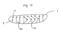
- the airbag 1 can include darts or longitudinal seams 8 and circular seams 12 that extend in a curved manner or a bend to form the substantial "D" shape or ">" shape in the airbag 1.
- the airbag 1 includes a combination of generally straight line areas 106 and the curved or bent areas 108 formed by the darts 8 and circular seams 12.
- the transition area from the straight line area 106 to the curved seam area 108 is open.
- the transition area can also be covered by a fabric sheet or sheets.
- the transition area between the straight line area 106 to the curved seam area 108 can be formed by airbag chambers.
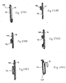
- FIGs 14(a) and 14(b) show another embodiment of the present invention.
- the airbag 200 can have tethers 201 as a connection member.
- the tethers 201 are interconnected among various points along the airbag 200 to form the bent or ">" shape in the airbag 200.
- the tethers 201 connect to the airbag 200 at various connection points 205.
- the airbag 200 can have a single kink or bend in each chamber 203 (similar to Figure 1 (a) ), or the airbag 200 can have multiple kinks or bends, as shown in Figure 14(b) .
- the tethers 201 can be attached to the airbag 200 at two or more places to force the formation of one or more bends or kinks in the airbag 200.
- the connection member 201 can also comprise a belt or rope or any other suitable device.
- the airbag 220 may have a combination of inter-chamber deformation with chamber deformation.
- Figures 15(a), 15(b) and 15(c) show an airbag 220 with multiple chambers 223. Chambers 223 in the upper center region of the airbag 220 are further deformed to cause the shape shown in Figure 15(c) .
- This inter-deformation and deformation aids in receiving the head H of an occupant during a collision event.
- the location of the inter-deformed chambers can be located in various positions in the airbag 220 and need not be located as shown in Figure 15(a) .
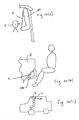
- the airbag 290 can have the connection member 91 located facing towards the occupant. Further, the airbag 290 can be positioned in multiple locations inside the vehicle, such as along the lower dashboard D to protect the knees of an occupant, or along the roof line R of a vehicle, as can be seen in Figures 16(b) and 16(c) .
- the airbag 290 can be positioned outside of a vehicle 295, such that a pedestrian or other individual outside of the vehicle can be protected in the case of a collision.
- the airbag 290 can be positioned with the connection member 91 facing the vehicle 295 or away from the vehicle 295.
- the airbag 300 is configured to inflate into a position wherein an enveloped space Y is defined by the first side surface 302 and a plane containing the upper and lower ends of the airbag 305, which can be seen in Figure 18 .
- the ratio of the volume of the enveloped space Y over the volume V of the inflated airbag 300 is greater than approximately 1.0. In another embodiment, the ratio is greater than approximately 1.2.
- a longitudinal length X of the connection member 91 is smaller than a longitudinal length L of the airbag 300.
- the ratio of the longitudinal distance L of the airbag 300 to the longitudinal length X of the connection member 91 is approximately 1.2 or greater. In another embodiment, the ratio of the longitudinal distance L of the airbag 300 to the longitudinal length X of the connection member 91 is approximately 1.25.
- the airbag 300 comprises an effective space factor defined as the stroke length Z divided by the inflation volume V of the airbag 300.
- the effective space factor of an airbag 300 in an embodiment of the present invention is approximately 7.5.
- the airbag 300 comprises an effective space factor greater than 7.5.
- a width of each of the plurality of chambers at the intermediate portion of the airbag 300 is smaller than a width of each of the plurality of chambers at the upper and lower ends of the airbag 300.
- the airbag 90 is part of an occupant safety system 320.
- the occupant safety system 320 includes an Electronic Control Unit 325 configured to determine a vehicle collusion and to trigger deployment of the airbag 90.
- a Seat Weight Sensor 330 can also be included in the occupant safety system 320, which is configured to determine a vehicle occupant's weight and/or position.
- the occupant safety system 320 can also include a Motorized Seat Belt device 335, which can be controlled by the Electronic Control Unit 325.
- Figure 20 is an example which is not part of the current invention in which a bend in the airbag 350 is formed by the shape of the chambers 353 of the airbag 350.
- the curves of seams 352 may be used to decrease the thickness of a chamber 353, as shown in Figure 20 . This causes a weakening of the airbag 350 in the region of the seam curves 352 and creates a bend in the airbag 350.
- a bend line 354 is an arrangement of neighbouring chambers 353 with weakened zones 356.
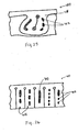
- Figure 21 is an embodiment of the current invention in which silicon lines 358 are used to weaken airbag chambers 353.
- the silicon weakens the airbag 350 by decreasing the diameter of the airbag 350 along a bent line 354.
- lines of silicon 358 may include strips of silicon or straps of silicon. Silicon based materials may be used, including silicone.
- the silicon lines 358 may fail and fall off of the airbag.
- the silicon lines 358 may fail by cracking or breaking. Failure of the silicon lines 358 may occur fully, partially, or not at all.
- Figure 22 shows another example, which is not part of the invention, in which seams 357 between airbag chambers 353 may be used to form bends in an airbag 350.
- seams 357 placed between chambers 353 may be reaped together to form a fold or bent line in the airbag 350. This causes a buckle 359 on one side of the airbag 350 and a dell 360, or valley, on the other side of the airbag 350.
- a common seam 357 formed in the airbag 350 may be 3-5 cm long.
- Figure 23 shows a further embodiment of the present invention that is similar to the airbag of Figure 22 but also includes a connection member 91 to enhance airbag 350 bending or buckling.
- Figure 24 shows example which is not part of the present invention in which an airbag 380 with a flower shape is used.
- three or more chambers 381, 382, 383 may be used to form the "petals" of a flower.
- the chambers 381, 382, 383 form a double D-shape, with the middle chamber 382 serving as an absorber element for forces along the longitudinal direction of the middle chamber 382.
- silicon strips 402 are used to separate airbag chambers 408 into smaller chambers.
- silicon strips 402 separate a chamber 408 into two smaller chambers with less volume. This causes a fast airbag 400 deployment and fast positioning of the airbag 400.
- One or more silicon strips 402 may be used and the strips 402 may be parallel or non-parallel.
- lines of silicon 402 may include strips of silicon or straps of silicon.
- Silicon based materials may be used, including silicone.
- the silicon strips 402 may fail and allow the airbag 400 to inflate to full volume.
- the silicon lines 402 may fail by cracking or breaking. Failure of the silicon lines 402 may occur fully, partially, or not at all.
- silicon strips 402 are used to further divide airbag chambers 408.
- an airbag 420 is pre-folded before the process of folding so that length of an airbag 420 and a connecting member 91 are equalized or so that the airbag 420 is arranged with two sides of equal length.
- one or more pre-folds may be necessary to obtain a flat layered package.
- Figure 27f illustrates an airbag 420 with an airbag layer 421 and a connection member 91.
- Figures 27a, 27b, 27c, 27d, and 27e illustrate various examples of pre-folds for airbags 420.
- an airbag 420 is pre-folded prior to packaging the airbag 420 by using a rolled fold, zig-zag fold, plus-1, or a combination of different pre-fold types.
- Figures 28a, 28b, 28c, 28d, 28e, and 28f illustrate various examples of pre-folds and pre-fold combinations for airbags 420.
- Figure 29a shows an example of another embodiment of the present invention in which an airbag 440 with a double-sided D-shape is used.
- the airbag 440 may be formed by two D-shaped airbags.
- a double-sided D-shaped airbag includes a connection member 91 in its middle.
- Figure 29b shows an end view of a double-sided D-shaped airbag 440.
- primary airbag chambers 455 may be connected to secondary airbag chambers 457 so that the secondary chambers 457 are filled by gas passing from the primary chambers 455.
- a seam 458 is used to create secondary chambers 457 that are filled from below by gas flowing from primary chambers 455.
- Such arrangements allow for fast positioning and the use of seams 458 also allow bending of the airbag 450 along a bent line 459. Bending of the airbag 450 due to the seams 458 may be sufficient to shape the bag 450 without further bending means.
- Figure 31 shows a further example which is not part of the present invention that uses seams 458 positioned near the top of the airbag 450 to divide chambers 453 into primary 455 and secondary 457 chambers.
- Such designs allow for fast positioning with fewer circular seams 460 in the upper region of the airbag 450.
- a bent line may be created via horizontal tensioning or by any of the methods described above.
- inner tether layers 510 may be used to shape an airbag 500.
- a double-V fabric is seamed in the middle of an airbag 500 to form the airbag 500 into an X-shape.
- the double-V fabric, or X-tether 510 may be sewn together with the existing seams at the edges.
- Such inner tethers 510 may be used to limit the extension of the airbag 500.
- Figure 32b shows an end-view of a cross-section of an airbag 500 with an X-tether 510.
- a strap 530 that is fixed to a point on a vehicle is used.
- a strap 530 may be fixed to the roof R inside of a vehicle.
- a strap 530 is fixed to the roof R of a vehicle and to an airbag 520 with a connection member 91.
- an airbag 520 without a bend or connection member is attached to a strap 530 that is fixed to the inside roof R of a vehicle.
- an airbag 520 without bent straps at its lower edge is attached to a strap 530 that is fixed to the inside roof R of a vehicle.
- Other variations may be achieved through direct protection of a strap 530, through positioning of the airbag 520, or combinations of the methods described above.
Landscapes
- Engineering & Computer Science (AREA)
- Mechanical Engineering (AREA)
- Air Bags (AREA)
- Automotive Seat Belt Assembly (AREA)
Description
- The present invention relates to an airbag for protecting the head of a vehicle occupant, and more particularly, to a head protection airbag which is constructed so as to be deployed along a side door pillar and the like upon a side impact or a roll-over of a vehicle. Also, the present invention relates to a head protection airbag device having the head protection airbag.
- As is generally known in the art, an airbag for protecting the head of a vehicle occupant is installed adjacent to a corner of a vehicle interior where a roof panel and a side panel are joined to each other, and is constructed so as to be deployed along a side door window and the like when gas is introduced therein from an inflator through a gas inlet.
- International Publication No.
WO 97/06987 claim 1, which is deployed on the side of a vehicle occupant. In the side airbag, a longitudinal intermediate portion of a bag is constricted by a seam which extends in a transverse direction (a lengthwise direction of a vehicle body: this also applies to the following description), so that the bag is divided into an upper portion and a lower portion. A panel is positioned along a portion of the airbag which faces the vehicle occupant. The upper and lower portions of the panel are respectively connected to the upper and lower portions of the bag. When the bag is inflated, the panel is tightly stretched. Then, as the shoulder of the occupant comes into contact with the bag, the panel pulls the upper portion of the bag downward. As such, the upper portion of the bag is pulled toward the vehicle occupant to protect the head of the vehicle occupant. - Japanese Unexamined Patent Application Publication No.
2003-72500 - In the case where the airbag disclosed in International Publication No.
WO 97/06987 - In the case of the head protection airbag disclosed in Japanese Unexamined Patent Application Publication No.
2003-72500 - Further,
US 5 636 862 A discloses an airbag assembly comprising an airbag and a tether having a first end connected to the airbag and a second end connected to the vehicle. - Accordingly, it is an object of the present invention to provide a head protection airbag which eliminates the need to employ an inflator having a large capacity and which is capable of immediately protecting the head of a vehicle occupant, thereby sufficiently absorbing a shock applied to the head of the vehicle occupant, and a head protection airbag device having the head protection airbag.
- The invention relates to an airbag device. The airbag device comprises an airbag having first and second side surfaces and upper and lower ends; a member connecting the upper and lower ends of the airbag; wherein the airbag is configured to inflate into a position wherein an enveloped space is defined by the first side surface and a plane containing the connecting member. Further, the airbag includes an intermediate portion and comprises a first panel and a second panel connected to form a chamber,
- wherein a plurality of chambers are formed between the first panel and the second panel,
- wherein the plurality of chambers extend longitudinally in the airbag, wherein a width of each of the plurality of chambers at the intermediate portion of the airbag is smaller than a width of each of the plurality of chambers at the upper and lower ends of the airbag, the widths being measured in the transverse direction of the airbag.
- The ratio of the volume of the enveloped space over the volume of the inflated airbag may be greater than approximately 1.0.
- According to an embodiment of the present invention, an occupant safety system is provided. The occupant safety system comprises an airbag having first and second side surfaces and upper and lower ends, a member connecting the upper and lower ends of the airbag, and an inflator for inflating the airbag. The airbag is configured to inflate into a position wherein an enveloped space is defined by the first side surface and a plane containing the connecting member.
- It is to be understood that both the foregoing general description and the following detailed description are exemplary and explanatory only, and are not restrictive of the invention as claimed.
- These and other features, aspects, and advantages of the present invention will become apparent from the following description, appended claims, and the accompanying exemplary embodiments shown in the drawings, which are briefly described below.
-
Figs. 1 (a) and 1 (b) are diagrammatic side views illustrating deployed states of head protection airbags in accordance with embodiments of the present invention. -
Figs. 2(a), 2(b) and 2(c) are views explaining the operation of the airbag shown inFig. 1(a) . -
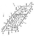
Fig. 3 is a perspective view illustrating a head protection airbag in accordance with an embodiment of the present invention, which is viewed from the side of a vehicle occupant and is maintained in an un-deployed state. -
Fig. 4 is a perspective view illustrating a state in which a bag of the head protection airbag is pulled upward. -
Fig. 5 is a perspective view illustrating the head protection airbag which is viewed from the side of a vehicle body. -
Fig. 6 is a perspective view illustrating a state in which the head protection airbag is deployed and is viewed from the side of the vehicle occupant. -
Figs. 7(a), 7(b), 7(c), 7(d) and 7(e) are cross-sectional views taken along the lines A-A, B-B, C-C, D-D and E-E ofFig. 6 . -
Figs. 8(a) and 8(b) are explanatory views illustrating an example which is not part of the present invention. -
Figs. 9(a) and 9(b) are explanatory views illustrating another embodiment of the present invention. -
Fig. 10 is an explanatory view illustrating another embodiment of the present invention. -
Figs. 11 (a) and 11 (b) are explanatory views illustrating still another embodiment of the present invention. -
Figs. 12(a), 12(b), and 12(c) are explanatory views illustrating an example which is not part of the present invention. -
Fig. 13 is a view of an airbag according to another embodiment of the present invention. -
Figs. 14(a) and 14(b) are views of an airbag according to another embodiment of the present invention.Fig. 14(a) is a perspective view andFig. 14(b) is a side view of the airbag shown inFig. 14(a) . -
Figs. 15(a), 15(b) and 15(c) are views of an airbag according to another embodiment of the present invention.Fig. 15(a) is a perspective view.Fig. 15(b) is a side view taken along line A-A inFig. 15(a). Fig. 15(c) is a view taken along line B-B inFig. 15(a) . -
Figs. 16(a), 16(b) and 16(c) are views of an airbag according to another embodiment of the present invention.Fig. 16(a) is a view of an airbag with a connecting member facing the occupant.Fig. 16(b) is a view of an airbag positioned on a lower dashboard in a vehicle.Fig. 16(c) is a view of an airbag positioned on a roof line of a vehicle. -
Figs. 17(a) and 17(b) are views of an airbag according to another embodiment of the present invention.Fig. 17(a) is a view of an airbag with a connecting member facing the vehicle body.Fig. 17(b) is a view of an airbag with the connecting member facing away from the vehicle body. -
Fig. 18 is a view of an airbag. -
Fig. 19 is a schematic view of an occupant protection system according to an embodiment of the present invention. -
Fig. 20 is a view of an airbag according to an example which is not part of the present invention. -
Fig. 21 is a view of an airbag according to another embodiment of the present invention. -
Fig. 22 is a view of an airbag according to an example which is not part of the present invention. -
Fig. 23 is a view of an airbag according to another embodiment of the present invention. -
Fig. 24 is a view of an airbag in a "flower" shape according to another example which is not part of the present invention. -
Fig. 25 is a view of an airbag according to another an example which is not part of the present invention. -
Fig. 26 is a view of an airbag according to an example which is not part of the present invention. -
Figs. 27(a) - 27(f) are views of an airbag with pre-folds according to another embodiment of the present invention. -
Figs. 28(a) - 28(f) are views of an airbag with pre-folds and following folding variations according to another embodiment of the present invention. -
Figs. 29(a) and 29(b) are views of an airbag in a "double D" shape according to another embodiment of the present invention.Fig. 29(a) is a perspective view andFig. 29(b) is a side view. -
Fig. 30 is a view of an airbag according to an example which is not part of the present invention. -
Fig. 31 is a view of an airbag according to an example which is not part of the present invention. -
Figs. 32(a) and 32(b) are views of an airbag according to an example which is not part of the present invention.Fig. 32(a) is a perspective view of an airbag with tethers.Fig. 32(b) is an end-view of a cross-section taken along line A-A inFig. 32(a) . -
Figs. 33(a) - 33(c) are views of an airbag with a strap attached to the roof line of a vehicle according to an example which is not part of the present invention. - According to a first aspect of the present invention, there is provided a head protection airbag according to
claim 1. - When a vehicle occupant comes into contact with the head protection airbag according to the present invention, the intermediate portion of the bag protects the head of the vehicle occupant while gradually withdrawing toward the vehicle body. By this withdrawal, a force is applied to the bag such that the upper part and the lower part of the bag are diverged from each other. The force is opposed by the connection member. Therefore, the intermediate portion of the bag gradually withdraws toward the vehicle body while protecting the head of the vehicle occupant. At this time, the shock applied to the head of the vehicle occupant is absorbed. After the intermediate portion which has caught the head of the vehicle occupant comes into contact with the vehicle body, the bag is depressed to absorb the shock applied to the head of the vehicle occupant.
- Since the projection of the intermediate portion of the bag projects toward the vehicle occupant, the head of the occupant can be immediately caught by the bag and a shock can be absorbed throughout an extended period of time. While the bag withdraws, the reaction force which the head receives from the bag is relatively small. As a result, when the head of the vehicle occupant is initially caught by the bag, the reaction force that is applied to the head of the occupant from the bag is small.
- Hereafter, preferred embodiments of the present invention will be described with reference to the attached drawings.
- In the description given below, a transverse direction means a forward and rearward direction of a vehicle in which a head protection airbag according to the present invention is installed, and a longitudinal direction means an upward and downward direction of the vehicle in which the head protection airbag according to the present invention is deployed in a vehicle interior.
- All head protection airbags (hereinafter, simply referred to as "airbags") according to various embodiments of the present invention as will be sequentially described below in detail are installed along a side portion of a roof panel, for example, to extend from an A pillar to a C pillar in their folded state, and are inflated and deployed in the shape of a curtain along a side surface of the vehicle interior when a side impact or a roll-over of the vehicle occurs, to protect the head of a vehicle occupant seated on a front seat or a rear seat in the vehicle interior, thereby preventing the head of the vehicle occupant from colliding with the side surface of the vehicle interior or the vehicle occupant from being ejected through a window of the vehicle.
- An
airbag 90 shown inFig. 1(a) comprises abag 95 which is bent in the shape of'<' in an inflated state, and aconnection member 91 which is positioned on a side of thebag 95, facing a vehicle body, and connects upper and lower portions of thebag 95 with each other. A longitudinal intermediate portion of thebag 95 which substantially corresponds to the middle of thebag 95 projects toward the vehicle occupant. The distance from theconnection member 91 to the projecting end of thebag 95 is designated byreference numeral 92. Aspace 99 is defined between the vertical projectingintermediate portion 95c and theconnection member 91. - In a
bag 95' of an airbag 90' shown inFig. 1(b) , a projectingintermediate portion 95c' is positioned lower than the middle of thebag 95'. Thebag 95' is'L'-shaped when viewed from the side. - The
connection members 91 and 91' of thebags Fig. 1 (b) , in addition to adoor 93, awindow 94 and aroof panel 98, the head H of the vehicle occupant which is caught by theintermediate portion 95c' of thebag 95' is also illustrated. - In a state in which each
bag connection member 91 in an upward direction, and a thicknesswise center line 'b' of a lower portion of the bag which extends downward from the bent portion of each bag gradually approaches theconnection member 91 in a downward direction. -
Figs. 2(a) and 2(b) are views illustrating a state in which the head H and the shoulder of the vehicle occupant are protected by theairbag 90 shown inFig. 1 (a) . - Referring to
Fig. 2(a) , the head H of the vehicle occupant initially comes into contact with theintermediate portion 95c of thebag 95 so as to push thebag 95 toward the vehicle body. The upper andlower portions bag 95 and theconnection member 91 define a triangular configuration. Accordingly, in opposition to aforce F 1 which is applied by the head H to thebag 95 to push thebag 95 toward the vehicle body, reaction forces F2 and F3 are generated in the upper andlower parts bag 95, so as to act in opposite directions which are parallel to the upper andlower parts bag 95 into thespace 99. In this way, a shock to the head H is gradually absorbed. Consequently, the speed at which the head H moves toward the vehicle body gradually decreases. - As a result, as shown in
Fig. 2(b) , thebag 95 comes into contact with thewindow 94 or the pillar (not shown) via theconnection member 91, and is then depressed against the vehicle body by the head. - In a state shown in
Fig. 2(b) , since the speed at which the head H moves toward the vehicle body is significantly decreased, the reaction force which is applied by thebag 95 to the head H is small. -
Fig. 2(c) is a graph showing changes in the reaction force which is applied to the head H by the airbag, with the lapse of time after a side impact of a vehicle occurs. - In the case of the
airbag 90, due to the fact that the intermediate portion 90c initially catches the head H, although the reaction force initially increases, after the initial stage, only a relatively low reaction force is generated. - On the contrary, in a comparative example in which an airbag is positioned adjacent to a window, because the head depresses the airbag from the start, a maximum value of the reaction force which is applied to the head from the airbag becomes greater than that in the case of the
airbag 90. - Next, a specific example of a head protection airbag according to the present invention will be described with reference to
Figs. 3 through 7 . - The
airbag 1 comprises abag 2 which is inflated to project toward the vehicle occupant, aconnection member 3 which is positioned at a side of thebag 2, facing the vehicle body, and is composed of a panel connecting the upper and lower portions of thebag 2 with each other, afront protruding portion 4 which is connected to theconnection member 3 so as to protrude forward, and a rear protrudingportion 5 which is connected to theconnection member 3 so as to protrude rearward. When thebag 2 is inflated, aspace 19 is defined between thebag 2 and the connection member 3 (seeFigs. 6 and7 ). - The
bag 2 is formed by sewing a first panel 6 (seeFig. 7 ) which faces the vehicle occupant with a second panel 7 which faces the connection member 3 (seeFig. 7 ). Sewing is implemented along a plurality oflongitudinal sewing lines 8, alower sewing line 9 which extends along the lower edges of thepanels 6 and 7, and anupper sewing line 10 which extends along the upper edges of thepanels 6 and 7. - Slightly below the upper ends of the
panels 6 and 7,openings 11 are defined through thepanels 6 and 7 and theconnection member 3, and sewing is implemented around each opening 11 along acircular sewing line 12. Thelongitudinal sewing line 8 is connected to thecircular sewing line 12. - A plurality of longitudinally
inflatable chambers 13 are defined between thelongitudinal sewing lines 8. A tunnel-shaped gas passage (a duct) 14 is defined between thecircular sewing lines 12 and theupper sewing line 10 to extend along theupper sewing line 10. - Furthermore, each of longitudinal intermediate portions of the
longitudinal sewing lines 8 is formed with a circularsewing line portion 8a or a semi-circularsewing line portion 8b. Between the circularsewing line portions 8a or between the circular and semi-circularsewing line portions chamber 13 has a decreased width. - A plurality of
tab pieces 18 are formed on an upper edge of theairbag 1.
Thetab pieces 18 are fastened to a roof side rail or the A pillar of the vehicle body by means of bolts, rivets, etc. - The
connection member 3 comprises a panel. As shown inFig. 5 , an upper portion of theconnection member 3 is sewn to thepanels 6 and 7 by thecircular sewing lines 12, and a lower edge of theconnection member 3 is sewn to thepanels 6 and 7 by thelower sewing line 9. - The length of the
connection member 3 which is measured from thecircular sewing line 12 to thelower sewing line 9 is smaller than that of thepanels 6 and 7 which are measured from thecircular sewing line 12 to thelower sewing line 9. - As shown in
Fig. 7(e) , thefront protruding portion 4 is formed by sewing a vehicle occupant-side panel 20 and a vehicle body-side panel 21 to each other along asewing line 22. In this preferred embodiment of the present invention, an upper edge of thepanel 20 is connected to thefirst panel 6, and an upper edge of thepanel 21 is connected to the second panel 7. - As shown in
Figs. 3 through 6 , thesewing line 22 comprises asewing line portion 22a which extends along the upper edges of thepanels sewing line portion 22b which extends along the front edges of thepanels sewing line portion 22c which extends along lower front edges of thepanels sewing line portion 22d for defining achamber 23,sewing line portions duct 24,sewing line portions 22g and 22i for forming aduct 25, and asewing line portion 22h for defining achamber 26. - The sewing line portion 22i sews the
panels connection member 3 to one another. The sewing line portion 22i extends upward along the rear edge of the front protrudingportion 4 and is connected to thecircular sewing line 12 which is formed at the front portion of thebag 2. - The
duct 24 is connected to theduct 14 and extends from the upper edge of the front protrudingportion 4 to the front edge thereof. Theduct 24 communicates with thechamber 23. Theduct 25 branches from a proximal end of theduct 24 and extends downward along the rear edge of the front protrudingportion 4. Theduct 25 communicates with thechamber 26. - A
strap 27 extends from the lowerportion protruding portion 4 to the front thereof. Thestrap 27 is connected to the A pillar of the vehicle body and functions so as to apply a tensile force to the lower edge of theinflated airbag 1. - The rear protruding
portion 5 is formed by sewing a vehicle occupant-side panel 30 and a vehicle body-side panel 31 (seeFig. 7 ) alongsewing lines sewing line 32 extends along the upper portions of thepanels sewing line 10. The upper portion of thepanel 30 is connected to thefirst panel 6, and the upper portion of thepanel 31 is connected to the second panel 7. - The
sewing line 32 comprises three longitudinalsewing line portions sewing line portions sewing line portions Chambers sewing line portions sewing line portions 33c and 33e. The sewing line portion 33e sews thepanels connection member 3 to one another. - An upper portion of the rear protruding
portion 5 defines agas inlet 36 which slightly projects rearward. Aduct 37 is formed along theupper sewing line 32. Theduct 37 communicates with theduct 14 and therespective chambers - The front end of the
airbag 1 is positioned adjacent to the A pillar, the rear end of theairbag 1 is positioned adjacent to the B pillar, and the upper edge of theairbag 1 is positioned to the roof side panel. Theairbag 1 is installed in a receiving space (not shown) for theairbag 1, defined in the vehicle body, in a state in which it is folded into an elongated configuration and extends in the transverse direction of the vehicle body. An inflator or a gas conduit is connected to thegas inlet 36. - The folded
airbag 1 which is received in the receiving space of the vehicle body is covered by a covering element such as a pillar trim, a roof trim, and the like. The covering element is pressed and opened by theairbag 1 when theairbag 1 is inflated, to allow the deployment of theairbag 1 into the vehicle interior. - Herein below, the operation of a head protection airbag device having the
airbag 1 constructed as mentioned above will be described. - If a side impact or a roll-over of a vehicle occurs, the inflator is actuated, and gas is supplied through the
ducts respective chambers airbag 1, whereby theairbag 1 is inflated. Theairbag 1 opens the covering element, is deployed downward in the shape of a curtain along the side surface of the vehicle interior, and is fully inflated between the vehicle occupant and the vehicle body as shown inFig. 6 to prevent the vehicle occupant from being brought into direct contact with the pillar, windows, etc. and from being ejected out of the vehicle. - In the
head protection airbag 1 according to the present invention, the deployment of theairbag 1 can vary depending on the location and size of the inflator pipe outlets in theairbag 1, amongst other things. - The
bag 2 is pulled downward by the forward and rear protrudingportions respective chambers 13 through theduct 14, thebag 2 is inflated. Because the upper and lower portions of thebag 2 are connected to theconnection member 3, the longitudinal intermediate portion of thebag 2 projects toward the vehicle occupant. In this preferred embodiment of the present invention, since the intermediate portions of therespective chambers 13 are decreased in width due to the presence of the circular and semi-circularsewing line portions Fig. 7(c) , while being inflated, thebag 2 is bent substantially in the shape of an arrow'<' along a line connecting the circular and semi-circularsewing line portions space 19 is defined between thebag 2 and theconnection member 3. Thespace 19 is opened to the atmosphere at the front and rear ends of thebag 2. - The vehicle occupant is protected by the airbag deployed and inflated as shown in
Fig. 6 . As in the case ofFig. 2 , since the head of the vehicle occupant comes into contact with and is protected by the intermediate portion of thebag 2, a shock applied to the vehicle occupant can be sufficiently absorbed, and as shown inFig. 2(c) , a maximum value of the reaction force which is applied to the vehicle occupant from thebag 2 is small. - Moreover, in this preferred embodiment of the present invention, as shown in
Figs. 3 and4 , the circular and semi-circularsewing line portions bag 2 is also gradually decreased in height toward the front side of the vehicle. This is to ensure that, since a vehicle occupant having a low sitting height has a tendency to place a seat to a more forward position, the bending portion of thebag 2 has a decreased height adjacent to the front side of thebag 2 to securely protect the head of the vehicle occupant. In this regard, a vehicle may be adopted, wherein the left height of a seat cushion is automatically raised when the vehicle occupant slides the seat forward. Therefore, in this case, it is preferred that the bending line of thebag 2 has the same height in the transverse direction. - An example of an airbag which is not part of the invention will be described below with reference to
Fig. 8 and other drawings.Fig. 8(b) is a cross-sectional view taken along the line B-B ofFig. 8(a) . - In an
airbag 1A shown inFigs. 8(a) and 8(b) , a longitudinal intermediate portion of abag 2A is sewn by atransverse sewing line 41, andchambers sewing line 41. Thesewing line 41 extends from the front edge of thebag 2A and to a position which is adjacent to the rear portion of thebag 2A. Between thesewing line 41 and the rear edge of thebag 2A, there is defined a communicatingportion 44 which communicates thechambers - Other constructions of the
airbag 1A are the same as those of theairbag 1, and therefore, the same reference numerals are used to designate the same parts. - When the
airbag 1A is inflated, thebag 2A and theconnection member 3 define a triangular configuration, and thespace 19 is defined between thebag 2A and theconnection member 3. Therefore, theairbag 1A according to this embodiment accomplishes the same effects as theairbag 1. - While the communicating
portion 44 is defined at the rear portion of thebag 2A inFig. 8 , it can be readily understood that the communicatingportion 44 can be defined at the front portion of thebag 2A and between the front and rear portions of thebag 2A. - In an
airbag 1B shown inFig. 9 ,non-inflatable panel parts 46 are installed between thechambers 13 of a bag 2B. The longitudinal intermediate portions of thechamber 13 are decreased in width by semi-circular sewing lines 8B. Other constructions are the same as those ofFig. 6 , and, therefore, the same reference numerals are used to designate the same parts. -
Fig. 9(b) is a cross-sectional view taken along the line B-B ofFig. 9(a) . - In the
airbag 1B, the bag 2B is inflated and bent at the longitudinal intermediate portion, and thespace 19 is defined between the bag 2B and theconnection member 3. Therefore, theairbag 1B according to this embodiment accomplishes the same effects as theairbag 1. Also, in this embodiment, since thepanel parts 46 are installed in the bag 2B and a small number ofchambers 13 are defined, even when an inflator having small capacity is employed, theairbag 1B can be quickly inflated. - An airbag 1' shown in
Fig. 10 is constructed in a manner such that, in theairbag 1, aloop part 50 is formed by atear seam 51 at a longitudinal intermediate portion of theconnection member 3. Other constructions are the same as those of theairbag 1. - The airbag 1' also accomplishes the same effects as the
airbag 1. In this preferred embodiment of the present invention, if a tensile force of no less than a predetermined level is applied to theconnection member 3 in the longitudinal direction, as thetear seam 51 is torn, the longitudinal length of theconnection member 3 increases. In this way, when thetear seam 51 is torn, a shock applied to the vehicle occupant is absorbed. - Also, instead of forming the
loop part 50 using thetear seam 51, a plurality ofshort slits 52 may be defined in aconnection member 3 "of anairbag 1" as shown inFig. 11 . - As shown in
Fig. 11 (b) (which is a cross-sectional view taken along the line B-B ofFig. 11 (a)) and Fig. 11(c) , if a tensile force of no less than a predetermined level is applied to theconnection member 3 "in the longitudinal direction, as theslits 52 are opened, the shock applied to the vehicle occupant is absorbed. Each slit 52 may be closed by a tear seam such that the tear seam can be torn by the application of a tensile force of no less than a predetermined level. Other constructions inFig. 11(a) are the same as those inFig. 5 . - An
exemplary airbag 60, which is not part of the invention, is shown inFig. 12 , the airbag comprising abag 61, aconnection member 62 which is positioned on a side of thebag 61, facing the vehicle body, and is composed of a panel for connecting the upper and lower portions of thebag 61 with each other, andside panels 63 serving as front and rear closing members for closing front and rear portions of theairbag 60. - In the
bag 61, as in the case of thebag 2, twopanels longitudinal chambers 66. Aduct 67 is formed along the upper edge of thebag 61, and gas can be supplied through agas inlet 68. Thepanels 63 comprise triangular panels which close sides of aspace 70 which is defined between thebag 61 and theconnection member 62. Thespace 70 communicates with the atmosphere through avent hole 71 which is defined in theconnection member 62. - Also in this example, the longitudinal intermediate portion of the
bag 61 is bent so as to project toward the vehicle occupant.
Specifically, in this example, when the vehicle occupant is brought into contact with thebag 61 to reduce the volume of thespace 70, as air existing in thespace 70 is discharged through thevent hole 71, the shock applied to the vehicle occupant is absorbed. - While the
vent hole 71 is defined in theconnection member 62 inFig. 12 , thevent hole 71 may be defined in theside panel 63. Also, in place of the vent hole, at least a portion of theconnection member 62 or theside panel 63 may be constructed of a fabric having air permeability. - The above-described embodiments are illustrated and explained by way of examples, and the present invention may have other constructions. For example, a belt may be used in place of the
connection member 3. Also, the airbags may be installed at other locations such as between the A pillar, C pillar, D pillar and so forth. Further the airbags may be installed outside of the vehicle, or directly on a seat or the dashboard of a vehicle. A combination of airbags may also be used. Furthermore, the shape of the airbag can vary. The airbag can inflate into a "D" or ">" shape, an "L" shape or a "V" shape, or other similar shape. - According to another embodiment of the present invention, the
airbag 1 can include darts orlongitudinal seams 8 andcircular seams 12 that extend in a curved manner or a bend to form the substantial "D" shape or ">" shape in theairbag 1. In this embodiment, shown inFigure 13 , theairbag 1 includes a combination of generallystraight line areas 106 and the curved orbent areas 108 formed by thedarts 8 andcircular seams 12. The transition area from thestraight line area 106 to thecurved seam area 108 is open. However, the transition area can also be covered by a fabric sheet or sheets. Further, the transition area between thestraight line area 106 to thecurved seam area 108 can be formed by airbag chambers. -
Figures 14(a) and 14(b) show another embodiment of the present invention. Theairbag 200 can havetethers 201 as a connection member. Thetethers 201 are interconnected among various points along theairbag 200 to form the bent or ">" shape in theairbag 200. Thetethers 201 connect to theairbag 200 at various connection points 205. Theairbag 200 can have a single kink or bend in each chamber 203 (similar toFigure 1 (a) ), or theairbag 200 can have multiple kinks or bends, as shown inFigure 14(b) . Thetethers 201 can be attached to theairbag 200 at two or more places to force the formation of one or more bends or kinks in theairbag 200. Theconnection member 201 can also comprise a belt or rope or any other suitable device. - In another embodiment of the present invention, the
airbag 220 may have a combination of inter-chamber deformation with chamber deformation. For example,Figures 15(a), 15(b) and 15(c) show anairbag 220 withmultiple chambers 223.Chambers 223 in the upper center region of theairbag 220 are further deformed to cause the shape shown inFigure 15(c) . This inter-deformation and deformation aids in receiving the head H of an occupant during a collision event. The location of the inter-deformed chambers can be located in various positions in theairbag 220 and need not be located as shown inFigure 15(a) . - According to another embodiment shown in
Figure 16(a) , theairbag 290 can have theconnection member 91 located facing towards the occupant. Further, theairbag 290 can be positioned in multiple locations inside the vehicle, such as along the lower dashboard D to protect the knees of an occupant, or along the roof line R of a vehicle, as can be seen inFigures 16(b) and 16(c) . - In another embodiment of the present invention shown in
Figures 17(a) and 17(b) , theairbag 290 can be positioned outside of avehicle 295, such that a pedestrian or other individual outside of the vehicle can be protected in the case of a collision. Theairbag 290 can be positioned with theconnection member 91 facing thevehicle 295 or away from thevehicle 295. - In another embodiment of the present invention, the
airbag 300 is configured to inflate into a position wherein an enveloped space Y is defined by thefirst side surface 302 and a plane containing the upper and lower ends of the airbag 305, which can be seen inFigure 18 . The ratio of the volume of the enveloped space Y over the volume V of theinflated airbag 300, according to an embodiment of the present invention, is greater than approximately 1.0. In another embodiment, the ratio is greater than approximately 1.2. - In another embodiment of the present invention, a longitudinal length X of the
connection member 91 is smaller than a longitudinal length L of theairbag 300.
In an embodiment, the ratio of the longitudinal distance L of theairbag 300 to the longitudinal length X of theconnection member 91 is approximately 1.2 or greater.
In another embodiment, the ratio of the longitudinal distance L of theairbag 300 to the longitudinal length X of theconnection member 91 is approximately 1.25. - In an airbag device of another embodiment, the
airbag 300 comprises an effective space factor defined as the stroke length Z divided by the inflation volume V of theairbag 300. The effective space factor of anairbag 300 in an embodiment of the present invention is approximately 7.5. In another embodiment, theairbag 300 comprises an effective space factor greater than 7.5. In an embodiment, a width of each of the plurality of chambers at the intermediate portion of theairbag 300 is smaller than a width of each of the plurality of chambers at the upper and lower ends of theairbag 300. - In another embodiment, as shown schematically in
Figure 19 , theairbag 90 is part of anoccupant safety system 320. Theoccupant safety system 320 includes anElectronic Control Unit 325 configured to determine a vehicle collusion and to trigger deployment of theairbag 90. ASeat Weight Sensor 330 can also be included in theoccupant safety system 320, which is configured to determine a vehicle occupant's weight and/or position. Additionally, theoccupant safety system 320 can also include a MotorizedSeat Belt device 335, which can be controlled by theElectronic Control Unit 325. -
Figure 20 is an example which is not part of the current invention in which a bend in theairbag 350 is formed by the shape of thechambers 353 of theairbag 350. For example, the curves ofseams 352 may be used to decrease the thickness of achamber 353, as shown inFigure 20 . This causes a weakening of theairbag 350 in the region of the seam curves 352 and creates a bend in theairbag 350. Abend line 354 is an arrangement of neighbouringchambers 353 with weakenedzones 356. -
Figure 21 is an embodiment of the current invention in whichsilicon lines 358 are used to weakenairbag chambers 353. The silicon weakens theairbag 350 by decreasing the diameter of theairbag 350 along abent line 354. For example, lines ofsilicon 358 may include strips of silicon or straps of silicon. Silicon based materials may be used, including silicone. During deflation, thesilicon lines 358 may fail and fall off of the airbag. For example, thesilicon lines 358 may fail by cracking or breaking. Failure of thesilicon lines 358 may occur fully, partially, or not at all. -
Figure 22 shows another example, which is not part of the invention, in which seams 357 betweenairbag chambers 353 may be used to form bends in anairbag 350. For example, seams 357 placed betweenchambers 353 may be reaped together to form a fold or bent line in theairbag 350. This causes abuckle 359 on one side of theairbag 350 and adell 360, or valley, on the other side of theairbag 350. Acommon seam 357 formed in theairbag 350 may be 3-5 cm long.Figure 23 shows a further embodiment of the present invention that is similar to the airbag ofFigure 22 but also includes aconnection member 91 to enhanceairbag 350 bending or buckling. -
Figure 24 shows example which is not part of the present invention in which anairbag 380 with a flower shape is used. For example, three ormore chambers Figure 24 , thechambers middle chamber 382 serving as an absorber element for forces along the longitudinal direction of themiddle chamber 382. - In an example which is not part of the present invention, as shown in
Figure 25 , silicon strips 402 are used to separateairbag chambers 408 into smaller chambers. In the example shown inFigure 25 , silicon strips 402 separate achamber 408 into two smaller chambers with less volume. This causes afast airbag 400 deployment and fast positioning of theairbag 400. One or more silicon strips 402 may be used and thestrips 402 may be parallel or non-parallel. For example, lines ofsilicon 402 may include strips of silicon or straps of silicon. Silicon based materials may be used, including silicone. As pressure increases inside anairbag 400 during deployment, the silicon strips 402 may fail and allow theairbag 400 to inflate to full volume. For example, thesilicon lines 402 may fail by cracking or breaking. Failure of thesilicon lines 402 may occur fully, partially, or not at all. In a further example, which is not part of the present invention, shown inFigure 26 , silicon strips 402 are used to furtherdivide airbag chambers 408. - In another embodiment of the present invention, an
airbag 420 is pre-folded before the process of folding so that length of anairbag 420 and a connectingmember 91 are equalized or so that theairbag 420 is arranged with two sides of equal length. To achieve equivalent lengths, one or more pre-folds may be necessary to obtain a flat layered package.Figure 27f illustrates anairbag 420 with anairbag layer 421 and aconnection member 91.Figures 27a, 27b, 27c, 27d, and 27e illustrate various examples of pre-folds forairbags 420. - In another embodiment of the present invention, an
airbag 420 is pre-folded prior to packaging theairbag 420 by using a rolled fold, zig-zag fold, plus-1, or a combination of different pre-fold types.Figures 28a, 28b, 28c, 28d, 28e, and 28f illustrate various examples of pre-folds and pre-fold combinations forairbags 420. -
Figure 29a shows an example of another embodiment of the present invention in which anairbag 440 with a double-sided D-shape is used. For example, theairbag 440 may be formed by two D-shaped airbags. A double-sided D-shaped airbag includes aconnection member 91 in its middle.Figure 29b shows an end view of a double-sided D-shapedairbag 440. - In another example, which is not part of the present invention,
primary airbag chambers 455 may be connected tosecondary airbag chambers 457 so that thesecondary chambers 457 are filled by gas passing from theprimary chambers 455. In the example shown inFigure 30 , aseam 458 is used to createsecondary chambers 457 that are filled from below by gas flowing fromprimary chambers 455. Such arrangements allow for fast positioning and the use ofseams 458 also allow bending of theairbag 450 along abent line 459. Bending of theairbag 450 due to theseams 458 may be sufficient to shape thebag 450 without further bending means. -
Figure 31 shows a further example which is not part of the present invention that usesseams 458 positioned near the top of theairbag 450 to dividechambers 453 into primary 455 and secondary 457 chambers. Such designs allow for fast positioning with fewercircular seams 460 in the upper region of theairbag 450. A bent line may be created via horizontal tensioning or by any of the methods described above. - In example which is not part of the present invention, inner tether layers 510 may be used to shape an
airbag 500. In the example shown inFigure 32a , a double-V fabric is seamed in the middle of anairbag 500 to form theairbag 500 into an X-shape. The double-V fabric, or X-tether 510, may be sewn together with the existing seams at the edges. Suchinner tethers 510 may be used to limit the extension of theairbag 500.Figure 32b shows an end-view of a cross-section of anairbag 500 with an X-tether 510. - In another embodiment of the present invention, a
strap 530 that is fixed to a point on a vehicle is used. For example, astrap 530 may be fixed to the roof R inside of a vehicle. In the embodiment illustrated inFigure 33a , astrap 530 is fixed to the roof R of a vehicle and to anairbag 520 with aconnection member 91. In the example, which is not part of the invention, illustrated inFigure 33b , anairbag 520 without a bend or connection member is attached to astrap 530 that is fixed to the inside roof R of a vehicle. In the example, which is not part of the invention, shown inFigure 33c , anairbag 520 without bent straps at its lower edge is attached to astrap 530 that is fixed to the inside roof R of a vehicle. Other variations may be achieved through direct protection of astrap 530, through positioning of theairbag 520, or combinations of the methods described above.
Claims (19)
- An airbag device for protecting a vehicle occupant, comprising: an airbag (1', 1" , 2, 2B, 200, 290) having first and second side surfaces and upper and lower ends; a member (3, 91, 201) connecting the upper and lower ends of the airbag; wherein the airbag (1', 1", 2, 2B, 220, 290) is configured to inflate into a position wherein an enveloped space is defined by the first side surface and a plane containing the connecting member, wherein
the airbag (1', 1" , 2, 2B, 220, 290) includes an intermediate portion and comprises a first panel (6) and a second panel (7) connected to form a plurality of chambers (13) there between characterized in that the plurality of chambers (13) extend longitudinally in the airbag (1', 1" , 2, 2B, 220, 290), wherein a width of each of the plurality of chambers (13) at the intermediate portion of the airbag is smaller than a width of each of the plurality of chambers (13) at the upper and lower ends of the airbag (2), the widths being measured in the transverse direction of the airbag (1', 1" , 2, 2B, 220, 290). - The airbag device of claim 1, wherein when the airbag (1', 1" , 2, 2B, 220, 290) deploys, the airbag (1', 1" , 2, 2B, 220, 290) forms a generally sideways "V" shape when viewed from the side.
- The airbag device of claim 1, wherein when the airbag (2) deploys, the airbag (1', 1" , 2, 2B, 220, 290) forms a generally "L" shape when viewed from the side.
- The airbag device of claim 1, wherein when the airbag (1', 1" , 2, 2B, 220, 290) deploys, the airbag (1', 1'', 2, 2B, 220, 290) and the connection member (3, 91, 201) together form a substantially "D" shape when viewed from the side.
- The airbag device of claim 1, wherein the intermediate portion is positioned lower than a center position of the airbag (1', 1" , 2, 2B, 220, 290) in a longitudinal direction.
- The airbag device of claim 1, wherein the intermediate portion is positioned approximately center of the airbag (1', 1" , 2, 2B, 220, 290) in a longitudinal direction.
- The airbag device of claim 6, wherein a longitudinal length of the first and second panels (6, 7) is greater than a longitudinal length of the connection member (3, 91, 201).
- The airbag device of claim 1, wherein the member (3, 91, 201) comprises a fabric panel.
- The airbag device of claim 1, wherein the member (3, 91, 201) comprises a tether.
- The airbag device of claim 1, wherein the member (3, 91, 201) connects to the airbag (1', 1" , 2, 2B, 220, 290) at additional connection points.
- The airbag device of claim 1, further comprising a plurality of members (3, 91, 201).
- An occupant safety system, comprising: an airbag device according to any of the preceding claims and an inflator for inflating the airbag.
- The occupant safety system of claim 12, further comprising an Electronic Control Unit configured to determine a vehicle collusion and to trigger deployment of the airbag (1' , 1" , 2, 2B, 220, 290).
- The occupant safety system of claim 12, further comprising a Seat Weight Sensor configured to determine a vehicle occupant's weight and/or position.
- The occupant safety system of claim 12, further comprising a Motorized Seat Belt device.
- The occupant safety system of claim 12, further comprising a plurality of airbags (1', 1" , 2, 2B, 220, 290).
- The occupant safety system of claim 12, wherein one of the plurality of airbags (1', 1" , 2, 2B, 220, 290)is a driver-side airbag.
- The occupant safety system of claim 12, wherein one of the plurality of airbags (1', 1" , 2, 2B, 220, 290) is a passenger-side airbag.
- The occupant safety system of claim 12, wherein one of the plurality of airbags (1', 1" , 2, 2B, 220, 290)is a side airbag.
Applications Claiming Priority (12)
| Application Number | Priority Date | Filing Date | Title |
|---|---|---|---|
| DE102004013364 | 2004-03-17 | ||
| DE102004013364 | 2004-03-17 | ||
| US62702504P | 2004-11-12 | 2004-11-12 | |
| US627025P | 2004-11-12 | ||
| US62717804P | 2004-11-15 | 2004-11-15 | |
| US627178P | 2004-11-15 | ||
| US62853904P | 2004-11-18 | 2004-11-18 | |
| US628539P | 2004-11-18 | ||
| US64648705P | 2005-01-25 | 2005-01-25 | |
| US646487P | 2005-01-25 | ||
| US65273105P | 2005-02-15 | 2005-02-15 | |
| US652731P | 2005-02-15 |
Publications (3)
| Publication Number | Publication Date |
|---|---|
| EP1577172A2 EP1577172A2 (en) | 2005-09-21 |
| EP1577172A3 EP1577172A3 (en) | 2006-01-18 |
| EP1577172B1 true EP1577172B1 (en) | 2012-11-14 |
Family
ID=46205506
Family Applications (1)
| Application Number | Title | Priority Date | Filing Date |
|---|---|---|---|
| EP05090062A Expired - Lifetime EP1577172B1 (en) | 2004-03-17 | 2005-03-10 | Airbag device |
Country Status (3)
| Country | Link |
|---|---|
| US (3) | US7828322B2 (en) |
| EP (1) | EP1577172B1 (en) |
| JP (1) | JP4797579B2 (en) |
Families Citing this family (132)
| Publication number | Priority date | Publication date | Assignee | Title |
|---|---|---|---|---|
| US20060202452A1 (en) * | 1994-05-23 | 2006-09-14 | Automotive Technologies International, Inc. | Side curtain and multi-compartment vehicular airbags |
| JP4063095B2 (en) * | 2002-03-08 | 2008-03-19 | 豊田合成株式会社 | Head protection airbag device |
| DE10303901A1 (en) * | 2003-01-31 | 2004-11-11 | Trw Occupant Restraint Systems Gmbh & Co. Kg | Airbag for a side impact protection device |
| JP4391308B2 (en) * | 2004-04-28 | 2009-12-24 | タカタ株式会社 | Airbag device |
| US7784822B2 (en) | 2004-07-26 | 2010-08-31 | Nxgen Technologies, Inc. | Inflatable airbag |
| JP4507848B2 (en) * | 2004-11-18 | 2010-07-21 | タカタ・ペトリ アーゲー | Head protection airbag and head protection airbag device |
| US7357408B2 (en) * | 2005-02-28 | 2008-04-15 | Autoliv Asp, Inc. | Inflatable curtain cushion tab shock absorption |
| US7513523B2 (en) * | 2005-08-18 | 2009-04-07 | Trw Vehicle Safety Systems Inc. | Inflatable curtain with different size panels |
| FR2900111B1 (en) * | 2006-04-24 | 2011-02-11 | Trw Automotive Gmbh | VEHICLE OCCUPANT RETENTION DEVICE WITH GAS CUSHION. |
| JP2008074248A (en) * | 2006-09-21 | 2008-04-03 | Takata Corp | Air bag device |
| US7823914B2 (en) * | 2007-05-14 | 2010-11-02 | Autoliv Asp, Inc. | Airbag mounting assembly and method of manufacture |
| DE102007028803B4 (en) * | 2007-06-19 | 2011-06-16 | Takata-Petri Ag | Airbag arrangement for a vehicle occupant restraint system |
| DE102007056848B4 (en) * | 2007-11-26 | 2018-10-11 | GM Global Technology Operations LLC (n. d. Ges. d. Staates Delaware) | Side airbag system, backrest and headrest |
| KR100941262B1 (en) * | 2007-12-13 | 2010-02-11 | 현대모비스 주식회사 | Airbag cushion |
| JP5314919B2 (en) * | 2008-04-23 | 2013-10-16 | 芦森工業株式会社 | Airbag device |
| JP2009274540A (en) * | 2008-05-14 | 2009-11-26 | Takata Corp | Curtain airbag and curtain airbag device |
| US7942444B2 (en) * | 2008-08-01 | 2011-05-17 | Tk Holdings Inc. | Airbag module |
| DE102009004883A1 (en) * | 2009-01-16 | 2010-07-22 | Volkswagen Ag | Head airbag module for a vehicle |
| US7992892B2 (en) * | 2009-02-27 | 2011-08-09 | Nissan North America, Inc. | Inflatable ramp for inflatable curtain side impact restraint |
| DE102009019766A1 (en) * | 2009-04-28 | 2010-01-28 | Takata-Petri Ag | Gas bag e.g. seat gas bag, for passenger-restraint system installed in e.g. seat of motor vehicle, has seam running along plane that is oriented diagonal or transverse to plane along which steering wheel ring and/or surface of panel extends |
| US7980585B2 (en) * | 2009-06-30 | 2011-07-19 | Autoliv Asp, Inc. | Airbag mounting assemblies with double-locking wrappers |
| US8196955B2 (en) * | 2009-07-01 | 2012-06-12 | Tk Holdings Inc. | Airbag system |
| JP2011020502A (en) * | 2009-07-14 | 2011-02-03 | Toyoda Gosei Co Ltd | Side air bag device |
| US8006998B2 (en) * | 2009-07-22 | 2011-08-30 | Autoliv Asp, Inc. | Inflatable airbag assemblies with modular components and related methods of manufacture |
| US8056924B2 (en) * | 2009-08-20 | 2011-11-15 | Autoliv Asp, Inc. | Inflatable airbag assemblies with alignment apertures |
| US8047564B2 (en) * | 2009-09-02 | 2011-11-01 | Tk Holdings Inc. | Airbag |
| US8240701B2 (en) * | 2009-09-08 | 2012-08-14 | Autoliv Asp, Inc. | Mounting assemblies with wrappers for inflatable curtain airbags |
| JP2011073516A (en) * | 2009-09-29 | 2011-04-14 | Toyoda Gosei Co Ltd | Airbag |
| JP5506348B2 (en) * | 2009-11-27 | 2014-05-28 | 日本プラスト株式会社 | Side airbag device |
| JP5338649B2 (en) * | 2009-12-16 | 2013-11-13 | タカタ株式会社 | Aircraft airbag, airbag device, and aircraft |
| US9150184B2 (en) * | 2009-12-29 | 2015-10-06 | Key Safety Systems, Inc. | Air bag having a slit in a border region |
| US8091918B2 (en) * | 2010-01-19 | 2012-01-10 | Autoliv Asp, Inc. | Double-sewn airbag mounting assemblies |
| JP5455732B2 (en) * | 2010-03-24 | 2014-03-26 | 日本プラスト株式会社 | Side airbag device |
| JP5502599B2 (en) * | 2010-05-31 | 2014-05-28 | タカタ株式会社 | Curtain airbag device |
| DE102010026932A1 (en) * | 2010-07-12 | 2012-01-12 | Autoliv Development Ab | Airbag with an external tension element and method for its production |
| GB2482341A (en) * | 2010-07-30 | 2012-02-01 | Ford Global Tech Llc | Curtain airbag for a motor vehicle |
| JP5471953B2 (en) | 2010-08-05 | 2014-04-16 | 豊田合成株式会社 | Head protection airbag device |
| US8360469B2 (en) * | 2010-08-27 | 2013-01-29 | Tk Holdings Inc. | Airbag system |
| JP5856405B2 (en) * | 2010-09-22 | 2016-02-09 | オートリブ ディベロップメント エービー | Curtain airbag |
| JP5551554B2 (en) * | 2010-09-29 | 2014-07-16 | 日本プラスト株式会社 | Curtain airbag device |
| JP5606876B2 (en) * | 2010-10-29 | 2014-10-15 | オートリブ ディベロップメント エービー | Curtain airbag |
| JP5336457B2 (en) * | 2010-11-18 | 2013-11-06 | トヨタ自動車株式会社 | Curtain airbag device |
| US8596673B2 (en) * | 2011-01-31 | 2013-12-03 | Trw Vehicle Safety Systems Inc. | Anti-ejection inflatable vehicle occupant protection device |
| EP2492156B1 (en) * | 2011-02-28 | 2014-03-05 | Autoliv Development AB | Pedestrian protection airbag for a vehicle |
| DE102011005057B4 (en) * | 2011-03-03 | 2015-11-05 | TAKATA Aktiengesellschaft | Airbag for a vehicle occupant restraint system of a motor vehicle and method for producing such a gas bag |
| JP5401495B2 (en) * | 2011-03-17 | 2014-01-29 | 富士重工業株式会社 | Side airbag device, occupant protection device, and occupant protection method |
| EP2502794B1 (en) * | 2011-03-25 | 2013-12-11 | Autoliv Development AB | A pedestrian airbag arrangement |
| US8408350B2 (en) | 2011-04-22 | 2013-04-02 | Tk Holdings Inc. | External airbag |
| US10040417B2 (en) * | 2011-05-02 | 2018-08-07 | Nxgen Technologies Llc | Side curtain airbag and method and apparatus for manufacturing a side curtain airbag |
| WO2012154852A2 (en) * | 2011-05-10 | 2012-11-15 | Tk Holdings Inc. | Side-impact airbag module |
| US8613466B2 (en) * | 2011-05-10 | 2013-12-24 | Tk Holdings Inc. | Side-impact airbag module |
| JP5334068B2 (en) * | 2011-06-13 | 2013-11-06 | トヨタ自動車株式会社 | Curtain airbag device |
| US8528932B2 (en) * | 2011-07-06 | 2013-09-10 | Zodiac Seats France | Deviating airbag |
| KR101326887B1 (en) | 2011-09-06 | 2013-11-11 | 현대자동차주식회사 | Curtain airbag with elasticity |
| US8684408B2 (en) * | 2011-09-24 | 2014-04-01 | GM Global Technology Operations LLC | Side impact airbag cushion |
| DE102011087449B4 (en) * | 2011-11-30 | 2019-04-25 | Autoliv Development Ab | Curtain airbag for a vehicle |
| EP2607183B1 (en) * | 2011-12-19 | 2015-04-08 | Autoliv Development AB | An inflatable airbag for a motor vehicle safety arrangement |
| US8480125B1 (en) | 2012-02-07 | 2013-07-09 | Ford Global Technologies, Llc | Curtain air bag system |
| US8789846B2 (en) * | 2012-03-07 | 2014-07-29 | Tk Holdings Inc. | Airbag device |
| US8439397B1 (en) | 2012-05-29 | 2013-05-14 | Toyota Motor Engineering & Manufacturing North America, Inc. | Airbags comprising hingedly affixed non-inflatable support members |
| JP2014004915A (en) * | 2012-06-25 | 2014-01-16 | Autoliv Development Ab | Side airbag device |
| DE102012213284A1 (en) * | 2012-07-27 | 2014-02-13 | Takata AG | Airbag arrangement for a vehicle occupant restraint system |
| JP5943767B2 (en) * | 2012-08-07 | 2016-07-05 | オートリブ ディベロップメント エービー | Curtain airbag for vehicle and method for manufacturing the same |
| DE102012214220B4 (en) | 2012-08-09 | 2017-06-08 | Takata AG | Airbag arrangement for a motor vehicle |
| CN104602972B (en) * | 2012-08-27 | 2017-09-22 | 丰田自动车株式会社 | Side air bag device for vehicle |
| US8740247B1 (en) * | 2012-12-27 | 2014-06-03 | Nissan North America, Inc. | Airbag assembly |
| US20140203541A1 (en) * | 2013-01-23 | 2014-07-24 | GM Global Technology Operations LLC | Vehicle side roof rail air bag |
| EP2765037B1 (en) * | 2013-02-12 | 2016-01-20 | Autoliv Development AB | A pedestrian airbag arrangement |
| US8851508B1 (en) * | 2013-03-15 | 2014-10-07 | Autoliv Asp, Inc. | Delayed vent in airbag curtain |
| US9511739B2 (en) * | 2013-05-08 | 2016-12-06 | GM Global Technology Operations LLC | Fender located pedestrian protection airbag |
| US9114776B2 (en) * | 2013-05-09 | 2015-08-25 | GM Global Technology Operations LLC | Vehicle and an airbag assembly for the vehicle |
| JP6183142B2 (en) * | 2013-10-22 | 2017-08-23 | タカタ株式会社 | Curtain airbag and curtain airbag device |
| KR101718690B1 (en) * | 2014-02-12 | 2017-04-04 | 아우토리브 디벨롭먼트 아베 | Side curtain airbag for vehicle |
| EP2942242B1 (en) * | 2014-05-08 | 2016-11-23 | Automotive Safety Technologies GmbH | Head airbag system for a vehicle and vehicle with a head airbag system |
| TWI562914B (en) * | 2014-05-30 | 2016-12-21 | Jamesyuming Pan | Airbag with multiple layers of cushioning effect |
| US9016717B1 (en) * | 2014-06-19 | 2015-04-28 | Toyota Motor Engineering & Manufacturing North America, Inc. | Curtain airbag for vertical and angular motion of occupant in rollover |
| DE102014212238B4 (en) * | 2014-06-25 | 2019-07-18 | Joyson Safety Systems Germany Gmbh | A gas bag for a vehicle occupant restraint system and method for folding a gas bag for a vehicle occupant restraint system |
| US9150187B1 (en) * | 2014-06-30 | 2015-10-06 | Nissan North America, Inc. | Curtain airbag assembly |
| KR101708223B1 (en) | 2014-07-14 | 2017-03-08 | 아우토리브 디벨롭먼트 아베 | Side curtain airbag for vehicle |
| JP6398430B2 (en) * | 2014-07-30 | 2018-10-03 | Joyson Safety Systems Japan株式会社 | Curtain airbag and curtain airbag device |
| KR102203274B1 (en) * | 2014-08-27 | 2021-01-18 | 현대모비스 주식회사 | Curtain Airbag Of Vehicle |
| KR101695234B1 (en) | 2014-10-01 | 2017-01-12 | 아우토리브 디벨롭먼트 아베 | Side curtain airbag for vehicle |
| KR101647445B1 (en) | 2014-11-27 | 2016-08-11 | 아우토리브 디벨롭먼트 아베 | Airbag for vehicle |
| JP6420157B2 (en) * | 2015-01-07 | 2018-11-07 | 芦森工業株式会社 | Airbag |
| KR101708200B1 (en) | 2015-03-24 | 2017-03-08 | 아우토리브 디벨롭먼트 아베 | Car curtain airbag |
| JP6097782B2 (en) * | 2015-03-31 | 2017-03-15 | 富士重工業株式会社 | Outside air bag |
| US9744938B2 (en) * | 2015-06-26 | 2017-08-29 | Jeffery L. Biegun | Passenger restraint housing for vehicle |
| JP6036932B2 (en) * | 2015-06-29 | 2016-11-30 | トヨタ自動車株式会社 | Curtain airbag device and occupant protection device |
| JP6578822B2 (en) * | 2015-08-28 | 2019-09-25 | Joyson Safety Systems Japan株式会社 | Curtain airbag |
| KR101708217B1 (en) | 2015-10-29 | 2017-03-08 | 아우토리브 디벨롭먼트 아베 | Airbag apparatus for vehicle |
| KR101724962B1 (en) * | 2015-12-09 | 2017-04-10 | 현대자동차주식회사 | Curtain airbag for vehicle |
| KR101836601B1 (en) * | 2016-03-04 | 2018-03-09 | 기아자동차주식회사 | Curtain airbag for vehicle |
| CN107235028B (en) * | 2016-03-29 | 2021-10-01 | 奥托立夫开发公司 | Airbag and airbag module |
| KR101776506B1 (en) * | 2016-06-08 | 2017-09-08 | 현대자동차주식회사 | Curtain airbag for vehicle |
| US9969346B2 (en) * | 2016-08-24 | 2018-05-15 | Ford Global Technologies, Llc | Airbag restraint system |
| JP6460070B2 (en) * | 2016-09-14 | 2019-01-30 | トヨタ自動車株式会社 | Curtain airbag device for vehicle |
| JP6558340B2 (en) * | 2016-10-07 | 2019-08-14 | トヨタ自動車株式会社 | Curtain airbag device for vehicle |
| US10220808B2 (en) | 2016-10-24 | 2019-03-05 | Toyota Motor Engineering & Manufacturing North America, Inc. | Systems, apparatuses, and methods of a button bridge installed with a curtain side airbag |
| DE102016120177A1 (en) * | 2016-10-24 | 2018-04-26 | Trw Automotive Gmbh | Airbag module |
| US10906494B1 (en) * | 2017-01-19 | 2021-02-02 | State Farm Mutual Automobile Insurance Company | Systems and methods for predicting occupant location based on vehicular collision |
| US10272868B2 (en) * | 2017-02-10 | 2019-04-30 | Ford Global Technologies, Llc | Roof mounted airbag assembly for rear seat |
| JP6831271B2 (en) * | 2017-03-08 | 2021-02-17 | Joyson Safety Systems Japan株式会社 | Curtain airbags and curtain airbag devices |
| JP6601804B2 (en) * | 2017-03-27 | 2019-11-06 | 株式会社Subaru | Crew protection device |
| JP6914074B2 (en) | 2017-03-29 | 2021-08-04 | 豊田合成株式会社 | Airbag for steering wheel |
| JP6537197B2 (en) * | 2017-03-31 | 2019-07-03 | 株式会社Subaru | Curtain airbag |
| JP6880954B2 (en) * | 2017-04-07 | 2021-06-02 | トヨタ自動車株式会社 | Vehicle side airbag device and its manufacturing method |
| KR102293580B1 (en) * | 2017-06-08 | 2021-08-26 | 현대모비스 주식회사 | Curtain airbag apparatus |
| KR102293583B1 (en) * | 2017-06-30 | 2021-08-27 | 현대모비스 주식회사 | Side airbag apparatus |
| JP6772987B2 (en) * | 2017-08-09 | 2020-10-21 | トヨタ自動車株式会社 | Vehicle curtain airbag device |
| DE102017125755B4 (en) | 2017-11-03 | 2025-01-30 | Joyson Safety Systems Germany Gmbh | vehicle occupant restraint system |
| DE102018103071B4 (en) | 2017-11-15 | 2024-03-07 | Joyson Safety Systems Germany Gmbh | Gas bag for a vehicle occupant restraint system of a motor vehicle |
| US10703321B2 (en) * | 2017-11-20 | 2020-07-07 | Ford Global Technologies, Llc | Airbag assembly |
| US10513206B2 (en) * | 2017-11-21 | 2019-12-24 | Ford Global Technologies, Llc | Vehicle seat |
| GB2569559B (en) * | 2017-12-19 | 2020-05-06 | Ford Global Tech Llc | Side curtain airbag |
| KR102064843B1 (en) * | 2018-04-23 | 2020-01-10 | 아우토리브 디벨롭먼트 아베 | Airbag apparatus of vehicle |
| US10583799B2 (en) | 2018-05-02 | 2020-03-10 | Autoliv Asp, Inc. | Overhead inflatable airbag assembly |
| EP3594070B1 (en) * | 2018-07-13 | 2021-01-13 | Volvo Car Corporation | Knee airbag arrangement comprising external tether |
| EP3643567B1 (en) * | 2018-10-24 | 2021-05-05 | Volvo Car Corporation | Airbag arrangement |
| DE102018128987A1 (en) * | 2018-11-19 | 2020-05-20 | Dalphi Metal Espana, S.A. | SIDE GAS BAG FOR A VEHICLE SECURITY SYSTEM OF A MOTOR VEHICLE AND VEHICLE SECURITY SYSTEM |
| US11130466B2 (en) | 2019-03-08 | 2021-09-28 | Trw Vehicle Safety Systems Inc. | Airbag with deployment controlling tether |
| DE102019112861A1 (en) * | 2019-05-16 | 2020-11-19 | Dalphi Metal Espana, S.A. | VEHICLE occupant restraint system for a motor vehicle and motor vehicle |
| US11285905B2 (en) * | 2019-11-26 | 2022-03-29 | Honda Motor Co., Ltd. | Airbag assembly and method |
| WO2021126363A1 (en) | 2019-12-20 | 2021-06-24 | Zf Passive Safety Systems Us Inc | Roof mounted occupant safety system |
| US11203319B2 (en) * | 2020-01-14 | 2021-12-21 | Ford Global Technologies, Llc | Airbag inflation restraint with releasable extension |
| US11745688B2 (en) | 2021-01-05 | 2023-09-05 | Hyundai Mobis Co., Ltd. | Roof airbag for vehicle |
| US11623603B2 (en) * | 2021-04-26 | 2023-04-11 | Ford Global Technologies, Llc | Vehicle front airbag assembly with multiple chambers |
| DE102021118305A1 (en) | 2021-07-15 | 2023-01-19 | Autoliv Development Ab | Motor vehicle with airbag unit |
| US11623600B2 (en) * | 2021-07-21 | 2023-04-11 | ZF Passive Safety Systems US Inc. | Apparatus for covering a windshield opening of a vehicle |
| KR20230157715A (en) * | 2022-05-10 | 2023-11-17 | 현대모비스 주식회사 | Air bag for vehicle |
| US11845392B1 (en) * | 2022-06-30 | 2023-12-19 | Ford Global Technologies, Llc | Airbag surrounding seatback of vehicle seat |
| US11926277B1 (en) * | 2022-11-09 | 2024-03-12 | ZF Passive Safety Systems US Inc. | Knee airbag |
| EP4461606A1 (en) * | 2023-05-08 | 2024-11-13 | Volvo Car Corporation | Airbag module for a vehicle, vehicle comprising an airbag module, use of an airbag module and method for protecting an occupant by a collision using an airbag module |
Family Cites Families (33)
| Publication number | Priority date | Publication date | Assignee | Title |
|---|---|---|---|---|
| US3733091A (en) * | 1971-05-12 | 1973-05-15 | Gec Detroit | Occupant restraint cushion |
| JPS5012724A (en) * | 1973-06-06 | 1975-02-10 | ||
| JPH03186448A (en) | 1989-12-15 | 1991-08-14 | Takata Kk | Air bag for passenger |
| DE4223620A1 (en) * | 1991-07-18 | 1993-01-21 | Nippon Denso Co | AIR BAG DEVICE |
| DE4226954A1 (en) | 1992-08-14 | 1994-02-17 | Johann Berger | Airbag construction - uses jacquard weaving procedure on four beams |
| JPH08142789A (en) * | 1994-11-21 | 1996-06-04 | Tokai Rika Co Ltd | Air bag body for vehicle side part |
| US5730464A (en) * | 1995-08-11 | 1998-03-24 | General Motors Corporation | Air bag module with tether |
| US5636862A (en) * | 1995-09-07 | 1997-06-10 | General Motors Corporation | Air bag assembly with tether |
| US5884939A (en) * | 1995-09-22 | 1999-03-23 | Toyo Tire & Rubber Co., Ltd. | Air bag system for automotive passenger seat |
| DE29517372U1 (en) | 1995-11-02 | 1996-02-01 | Trw Repa Gmbh | Airbag side impact protection device |
| DE59712913D1 (en) * | 1996-06-14 | 2008-03-20 | Volkswagen Ag | airbag device |
| JPH1029480A (en) * | 1996-07-17 | 1998-02-03 | Nippon Seiko Kk | Vehicle collision detection device |
| DE19720585A1 (en) * | 1997-05-16 | 1998-11-19 | Porsche Ag | Side impact protection device for an occupant of a vehicle |
| US6029993A (en) * | 1997-10-06 | 2000-02-29 | Inova Gmbh Technische Entwicklungen | Side airbag device, method for operation thereof and vehicle seat therewith |
| JPH11321511A (en) * | 1998-05-11 | 1999-11-24 | Takata Kk | Air bag for front passenger seat and folding method therefor |
| DE19953563A1 (en) | 1998-11-09 | 2000-05-11 | Trw Repa Gmbh | Vehicle side airbag has retaining catch system of loose coiled threads between woven fabric layers to be pulled out on inflation and hold layers together with given gap between them |
| JP2001088643A (en) * | 1999-09-21 | 2001-04-03 | Takata Corp | Air bag device |
| DE10060667B4 (en) | 1999-12-07 | 2006-04-13 | Toyoda Gosei Co., Ltd. | Three-dimensional airbags for motor vehicles |
| JP2002046562A (en) | 2000-08-04 | 2002-02-12 | Takata Corp | Air bag |
| US6508486B1 (en) * | 2001-06-06 | 2003-01-21 | Delphi Technologies, Inc. | Door mounted side restraint |
| US6626456B2 (en) * | 2001-06-26 | 2003-09-30 | Autoliv Asp, Inc. | Apparatus and method for inflatable curtain wrap |
| GB2377913B (en) * | 2001-07-26 | 2004-09-01 | Autoliv Dev | Improvements in or relating to an air bag arrangement |
| JP2003072500A (en) | 2001-09-07 | 2003-03-12 | Takata Corp | Protective bag of automobile occupant head part |
| JP4063095B2 (en) * | 2002-03-08 | 2008-03-19 | 豊田合成株式会社 | Head protection airbag device |
| JP4184698B2 (en) * | 2002-04-11 | 2008-11-19 | 豊田合成株式会社 | Airbag device |
| JP3682502B2 (en) * | 2002-04-12 | 2005-08-10 | 本田技研工業株式会社 | Outside air bag apparatus |
| DE10224138A1 (en) * | 2002-05-24 | 2003-12-11 | Takata Petri Ag | Driver or front passenger airbag |
| DE10223830A1 (en) | 2002-05-28 | 2004-01-08 | Takata Corp. | Multi-part gas bag blank for an airbag of an occupant protection device for motor vehicles and method for producing an airbag from the airbag blank |
| DE10237574B4 (en) | 2002-08-14 | 2005-11-24 | Takata Corp. | Occupant protection device |
| US7296822B2 (en) * | 2002-11-22 | 2007-11-20 | Trw Vehicle Safety Systems Inc. | Inflatable windshield curtain |
| US7000944B2 (en) * | 2002-11-22 | 2006-02-21 | Trw Vehicle Safety Systems Inc. | Inflatable windshield curtain |
| EP1477372A1 (en) * | 2003-05-14 | 2004-11-17 | Delphi Technologies, Inc. | Safety device |
| US7413215B2 (en) * | 2003-09-17 | 2008-08-19 | Delphi Technologies, Inc. | Method and apparatus for providing an inflatable cushion for use with a vehicle door |
-
2005
- 2005-03-10 EP EP05090062A patent/EP1577172B1/en not_active Expired - Lifetime
- 2005-03-29 US US11/092,590 patent/US7828322B2/en not_active Expired - Fee Related
- 2005-11-04 JP JP2005321080A patent/JP4797579B2/en not_active Expired - Fee Related
-
2010
- 2010-07-12 US US12/834,778 patent/US7967334B2/en not_active Expired - Fee Related
- 2010-07-12 US US12/834,753 patent/US7922193B2/en not_active Expired - Fee Related
Also Published As
| Publication number | Publication date |
|---|---|
| JP4797579B2 (en) | 2011-10-19 |
| US20100276916A1 (en) | 2010-11-04 |
| JP2006137413A (en) | 2006-06-01 |
| US7922193B2 (en) | 2011-04-12 |
| US7828322B2 (en) | 2010-11-09 |
| EP1577172A3 (en) | 2006-01-18 |
| US20050206138A1 (en) | 2005-09-22 |
| EP1577172A2 (en) | 2005-09-21 |
| US7967334B2 (en) | 2011-06-28 |
| US20100276915A1 (en) | 2010-11-04 |
Similar Documents
| Publication | Publication Date | Title |
|---|---|---|
| EP1577172B1 (en) | Airbag device | |
| JP6373547B2 (en) | Crew restraint system | |
| US8328229B2 (en) | Airbag module | |
| US7770925B2 (en) | Airbag protection flap | |
| JP2722015B2 (en) | Airbag with inflation limiting device | |
| JP5083024B2 (en) | Airbag device | |
| US8641088B2 (en) | Side-impact airbag module | |
| US9517746B2 (en) | Bag-in-bag safety restraint with directional inflation | |
| US20010007391A1 (en) | Air bag apparatus for passenger seat | |
| US20040155439A1 (en) | Airbag, airbag device and vehicle | |
| WO2005039938A1 (en) | Side curtain air bag | |
| CN100411918C (en) | Deployment assist mechanism for side curtain airbags | |
| CN105026219A (en) | Head protection air bag device and method for folding air bag | |
| EP3741629B1 (en) | Airbag device | |
| US20160039383A1 (en) | Double fold and roll cushions for ic | |
| US7556286B2 (en) | Extended inflatable coverage of inflatable curtains | |
| EP1256491B1 (en) | Head-protecting bag device for occupants in an automobile | |
| EP2441627B1 (en) | An airbag arrangement for a motor vehicle | |
| JP2024522999A (en) | Frontal airbag system with deployment assist wrapper | |
| US7832759B2 (en) | Side airbag module for a motor vehicle | |
| CN100575153C (en) | Airbag device | |
| JP6769374B2 (en) | Curtain airbag |
Legal Events
| Date | Code | Title | Description |
|---|---|---|---|
| PUAI | Public reference made under article 153(3) epc to a published international application that has entered the european phase |
Free format text: ORIGINAL CODE: 0009012 |
|
| AK | Designated contracting states |
Kind code of ref document: A2 Designated state(s): AT BE BG CH CY CZ DE DK EE ES FI FR GB GR HU IE IS IT LI LT LU MC NL PL PT RO SE SI SK TR |
|
| AX | Request for extension of the european patent |
Extension state: AL BA HR LV MK YU |
|
| PUAL | Search report despatched |
Free format text: ORIGINAL CODE: 0009013 |
|
| AK | Designated contracting states |
Kind code of ref document: A3 Designated state(s): AT BE BG CH CY CZ DE DK EE ES FI FR GB GR HU IE IS IT LI LT LU MC NL PL PT RO SE SI SK TR |
|
| AX | Request for extension of the european patent |
Extension state: AL BA HR LV MK YU |
|
| 17P | Request for examination filed |
Effective date: 20060629 |
|
| AKX | Designation fees paid |
Designated state(s): DE FR GB SE |
|
| RAP1 | Party data changed (applicant data changed or rights of an application transferred) |
Owner name: TAKATA - PETRI AG |
|
| 17Q | First examination report despatched |
Effective date: 20080723 |
|
| REG | Reference to a national code |
Ref country code: DE Ref legal event code: R079 Ref document number: 602005036945 Country of ref document: DE Free format text: PREVIOUS MAIN CLASS: B60R0021160000 Ipc: B60R0021232000 |
|
| GRAC | Information related to communication of intention to grant a patent modified |
Free format text: ORIGINAL CODE: EPIDOSCIGR1 |
|
| RIC1 | Information provided on ipc code assigned before grant |
Ipc: B60R 21/232 20110101AFI20120425BHEP Ipc: B60R 21/2338 20110101ALI20120425BHEP |
|
| GRAP | Despatch of communication of intention to grant a patent |
Free format text: ORIGINAL CODE: EPIDOSNIGR1 |
|
| RAP1 | Party data changed (applicant data changed or rights of an application transferred) |
Owner name: TAKATA AG |
|
| GRAS | Grant fee paid |
Free format text: ORIGINAL CODE: EPIDOSNIGR3 |
|
| GRAA | (expected) grant |
Free format text: ORIGINAL CODE: 0009210 |
|
| AK | Designated contracting states |
Kind code of ref document: B1 Designated state(s): DE FR GB SE |
|
| REG | Reference to a national code |
Ref country code: GB Ref legal event code: FG4D |
|
| REG | Reference to a national code |
Ref country code: DE Ref legal event code: R096 Ref document number: 602005036945 Country of ref document: DE Effective date: 20130110 |
|
| PG25 | Lapsed in a contracting state [announced via postgrant information from national office to epo] |
Ref country code: SE Free format text: LAPSE BECAUSE OF FAILURE TO SUBMIT A TRANSLATION OF THE DESCRIPTION OR TO PAY THE FEE WITHIN THE PRESCRIBED TIME-LIMIT Effective date: 20121114 |
|
| PLBE | No opposition filed within time limit |
Free format text: ORIGINAL CODE: 0009261 |
|
| STAA | Information on the status of an ep patent application or granted ep patent |
Free format text: STATUS: NO OPPOSITION FILED WITHIN TIME LIMIT |
|
| 26N | No opposition filed |
Effective date: 20130815 |
|
| GBPC | Gb: european patent ceased through non-payment of renewal fee |
Effective date: 20130310 |
|
| REG | Reference to a national code |
Ref country code: DE Ref legal event code: R097 Ref document number: 602005036945 Country of ref document: DE Effective date: 20130815 |
|
| REG | Reference to a national code |
Ref country code: FR Ref legal event code: ST Effective date: 20131129 |
|
| PG25 | Lapsed in a contracting state [announced via postgrant information from national office to epo] |
Ref country code: GB Free format text: LAPSE BECAUSE OF NON-PAYMENT OF DUE FEES Effective date: 20130310 Ref country code: FR Free format text: LAPSE BECAUSE OF NON-PAYMENT OF DUE FEES Effective date: 20130402 |
|
| REG | Reference to a national code |
Ref country code: DE Ref legal event code: R082 Ref document number: 602005036945 Country of ref document: DE Representative=s name: MAIKOWSKI & NINNEMANN PATENTANWAELTE PARTNERSC, DE Ref country code: DE Ref legal event code: R081 Ref document number: 602005036945 Country of ref document: DE Owner name: JOYSON SAFETY SYSTEMS GERMANY GMBH, DE Free format text: FORMER OWNER: TAKATA AG, 63743 ASCHAFFENBURG, DE |
|
| PGFP | Annual fee paid to national office [announced via postgrant information from national office to epo] |
Ref country code: DE Payment date: 20200528 Year of fee payment: 16 |
|
| REG | Reference to a national code |
Ref country code: DE Ref legal event code: R119 Ref document number: 602005036945 Country of ref document: DE |
|
| PG25 | Lapsed in a contracting state [announced via postgrant information from national office to epo] |
Ref country code: DE Free format text: LAPSE BECAUSE OF NON-PAYMENT OF DUE FEES Effective date: 20211001 |