EP1577128A1 - Haltering für einen Stabilisator einer Fahrzeugfederung und dessen Montagemethode - Google Patents
Haltering für einen Stabilisator einer Fahrzeugfederung und dessen Montagemethode Download PDFInfo
- Publication number
- EP1577128A1 EP1577128A1 EP05290603A EP05290603A EP1577128A1 EP 1577128 A1 EP1577128 A1 EP 1577128A1 EP 05290603 A EP05290603 A EP 05290603A EP 05290603 A EP05290603 A EP 05290603A EP 1577128 A1 EP1577128 A1 EP 1577128A1
- Authority
- EP
- European Patent Office
- Prior art keywords
- ring
- bar
- notches
- ring according
- notch
- Prior art date
- Legal status (The legal status is an assumption and is not a legal conclusion. Google has not performed a legal analysis and makes no representation as to the accuracy of the status listed.)
- Granted
Links
Images
Classifications
-
- B—PERFORMING OPERATIONS; TRANSPORTING
- B60—VEHICLES IN GENERAL
- B60G—VEHICLE SUSPENSION ARRANGEMENTS
- B60G21/00—Interconnection systems for two or more resiliently-suspended wheels, e.g. for stabilising a vehicle body with respect to acceleration, deceleration or centrifugal forces
- B60G21/02—Interconnection systems for two or more resiliently-suspended wheels, e.g. for stabilising a vehicle body with respect to acceleration, deceleration or centrifugal forces permanently interconnected
- B60G21/04—Interconnection systems for two or more resiliently-suspended wheels, e.g. for stabilising a vehicle body with respect to acceleration, deceleration or centrifugal forces permanently interconnected mechanically
- B60G21/05—Interconnection systems for two or more resiliently-suspended wheels, e.g. for stabilising a vehicle body with respect to acceleration, deceleration or centrifugal forces permanently interconnected mechanically between wheels on the same axle but on different sides of the vehicle, i.e. the left and right wheel suspensions being interconnected
- B60G21/055—Stabiliser bars
- B60G21/0551—Mounting means therefor
-
- B—PERFORMING OPERATIONS; TRANSPORTING
- B60—VEHICLES IN GENERAL
- B60G—VEHICLE SUSPENSION ARRANGEMENTS
- B60G2202/00—Indexing codes relating to the type of spring, damper or actuator
- B60G2202/10—Type of spring
- B60G2202/13—Torsion spring
- B60G2202/135—Stabiliser bar and/or tube
-
- B—PERFORMING OPERATIONS; TRANSPORTING
- B60—VEHICLES IN GENERAL
- B60G—VEHICLE SUSPENSION ARRANGEMENTS
- B60G2204/00—Indexing codes related to suspensions per se or to auxiliary parts
- B60G2204/10—Mounting of suspension elements
- B60G2204/12—Mounting of springs or dampers
- B60G2204/122—Mounting of torsion springs
- B60G2204/1222—Middle mounts of stabiliser on vehicle body or chassis
-
- B—PERFORMING OPERATIONS; TRANSPORTING
- B60—VEHICLES IN GENERAL
- B60G—VEHICLE SUSPENSION ARRANGEMENTS
- B60G2204/00—Indexing codes related to suspensions per se or to auxiliary parts
- B60G2204/40—Auxiliary suspension parts; Adjustment of suspensions
- B60G2204/44—Centering or positioning means
-
- B—PERFORMING OPERATIONS; TRANSPORTING
- B60—VEHICLES IN GENERAL
- B60G—VEHICLE SUSPENSION ARRANGEMENTS
- B60G2206/00—Indexing codes related to the manufacturing of suspensions: constructional features, the materials used, procedures or tools
- B60G2206/01—Constructional features of suspension elements, e.g. arms, dampers, springs
- B60G2206/40—Constructional features of dampers and/or springs
- B60G2206/42—Springs
- B60G2206/427—Stabiliser bars or tubes
Definitions
- the invention relates to a stop ring to be mounted on a curved cylindrical stabilizer bar, entering the constitution of a motor vehicle suspension. It also concerns a bar stabilizer provided with such rings. It finally concerns a a method of manufacturing a stabilizer bar including the attachment of these rings.
- a stabilizer bar must have means allowing to stabilize it transversely to the longitudinal direction of the vehicle. This so-called “anti-tracking" function can be assured of different ways, for example with rings, necklaces or riders attached to the bar.
- a ring comprising a simple solid ring about 5 mm thick, slipped on the bar before being crimped on it. Its resistance to tearing depends on the initial clearance existing before crimping between the bar and the inner surface of the ring. An optimal value set between 1 and 3/10 th of a millimeter. With a low clearance of this order, one achieves a very high tearing force, greater than 400 daN, for a very low cost price.
- the breakout force is defined as the effort required to initiate the sliding of the ring on the bar, after crimping.
- the methods of manufacturing a stabilizer bar imply to shape said bar, that is to say in particular of the bend, before engaging the rings on the bar to fix them by crimping at predetermined locations thereof.
- the bar must be subjected to a quenching operation after bending: this is the reason why the ring is not threaded on the bar before bending, this being raised to a temperature above 850 ° C.
- the bending of the bar causes some ovalization, particularly if said bar is tubular. It may not be possible to engage rings after conformation of the bar, especially if one seeks to respect the optimal play indicated above. We are then led to increase this game at the expense of the quality of crimping, the strength of tearing being significantly reduced.
- the invention makes it possible to overcome this drawback by proposing a modification of the ring, increasing its crush deformability and allowing, without inconvenience, to increase the initial game defined above. More particularly, the invention relates to a crimp stop ring on a curved cylindrical stabilizer bar for vehicle suspension characterized in that it comprises a closed ring of inner diameter substantially greater than the diameter of the bar on which it is intended to be mounted and in that said ring has at least one inner slot and at least one notch exterior.
- the inner surface of the ring is cylindrical, outside the or notch areas. Of preferably, it will have a constant rectangular radial section outside of these notch areas.
- two notches are provided inside to the inside of the ring and two outside notches to the outer face of the ring. External and internal notches can be diametrically opposed, respectively. The notches outer and inner can be shifted by 90 °, circumferentially.
- Such a notch has a radial depth of between 1/3 and 2/3 of the thickness of the ring. Preferably, the depth of the notch extends about half the thickness of the ring.
- Such a notch has a substantially triangular radial profile.
- the bottom of the notch preferably presents a leave.
- the internal notches are smaller than the outer notches. They are also more large number.
- the radial depth of an inner notch (distance between the inner casing of the ring and the bottom of the leave) will be of the order of 0.5 mm or less.
- the invention is particularly indicated when the rings must be crimped on tubular portions of the stabilizer bar, especially if such a bar is entirely tubular.
- the invention also relates to a method of manufacturing a stabilizer bar comprising the operation of bending a bar cylindrical to give it a desired shape, characterized in that, after to have bent said bar, it engages on the bar a stop ring conform to the above definition and in that this ring is crimped to a selected location on a cylindrical portion of said bar.
- a tool adapted to such crimping includes two jaws each having an imprint comprising an area semicylindrical bearing radius slightly greater than the outer radius of the bar and a groove of shape corresponding to that of said ring, dug into this support zone. Each groove is consistent and dimensioned to cause radial narrowing of the ring absorbing the relatively large clearance and ensuring effective crimping.
- the jaws are tightened until permanent deformation of the ring. We obtain a significant tearing force despite an initial game more large than in the prior art to easily engage the ring on a cylindrical bar already bent.
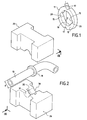
- the stop ring 11 shown in Figure 1 comprises a closed ring 12 of inner diameter D substantially greater than the outer diameter of a cylindrical bar 13 on which it is intended to be mounted.
- the stop ring comes down to the ring itself.
- the ring comprises at least one inner notch 15 and at least one outer notch 17. It further comprises a substantially cylindrical inner surface 19 outside the notch zones.
- the ring has a constant rectangular radial section outside these notch areas.
- each notch 15, 17 extends over the entire longitudinal dimension 1 of the ring.
- the ring has two internal notches 15 and two outer notches 17. The two outer notches and the two inner notches are diametrically opposed, respectively.
- each notch has a depth of about half the thickness of the ring. More generally, each notch may have a radial depth of between 1/3 and 2/3 of the thickness of the ring, approximately.
- Each notch has a substantially triangular radial profile. Of this fact, as each notch extends over the entire dimension longitudinal of the ring, such a notch has two flat faces defining substantially between them a dihedron, in this case a dihedral right. The bottom of the notch nevertheless presents a leave of absence of low radius of curvature.
- FIG. 2 illustrates a section of the stabilizer bar 13, cylindrical and tubular, already bent and on which we are about to crimp a stop ring 11 according to Figure 1, using a crimping tool constituted by two jaws 25, 26 which will be described in more detail below.
- a bent stabilizer bar has two stop rings of this kind, immobilized at selected locations, here by crimping according to the invention.
- the inner diameter of the ring is "substantially greater than the diameter of the bar on which it is intended to be mounted" it essentially means that this diameter is determined taking into account, or even This is a function of this maximum chord value, so that it is certain that the ring can be passed beyond the elbow to its crimping location.
- the inside diameter of the ring is greater (by at least one predetermined functional clearance) than the length of said maximum chord, it can be considered that one of the conditions for implementing the invention is realized. . It was determined that the optimal running clearance should be close to 2/10 th of a millimeter, for bar diameters generally between 10 and 30 mm.
- the ring mounting conditions are optimal, that is to say that we can certainly pass the ring on the bar to the crimping location and that crimping will also be optimized, with the crimping device described later.
- the inner diameter of the ring can be 8% to 15% greater than the nominal outside diameter of the bar on which it is intended to be crimped.
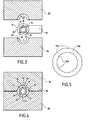
- FIG 5 there is shown another embodiment a ring 12a for forming a stop ring, which is remarkable mainly in that the inner slots 15a are smaller than the outer notches 17a.
- the total volume of the internal notches is substantially equal to the total volume of the external notches.
- the depth of the internal notches 15a could very advantageously be close to 0.5 mm, possibly less. Indeed, after crimping, said notches lose their height and the coating of the bar that is applied after crimping by dusting and baking is thick enough to cover completely the radially innermost part of the bar and "absorb" said notches, eliminating possible points priming corrosion.
- the number of internal notches is twice the number external notches. So, for a ring with an inner diameter of 21.8 mm and an outer diameter of 31.8 mm for a tube of 20.7 mm. There are 16 internal notches 15a and 8 notches outside 17a. Internal and external notches are staggered circumferentially, as shown, two internal notches located in the angular sector defined between two external notches consecutive.
- the ring 12a having a radial section rectangular (actually here square 5 mm side) outside areas notch.
- the notches extend over the entire longitudinal dimension of the ring. They have a substantially triangular radial profile with a background presenting a leave. The two flat faces of each notch define between them substantially a straight dihedron.
- a method of manufacturing the stabilizer bar therefore comprises the operation of bending a bar cylindrical to give it a desired shape. Then we make him undergo a quenching operation. Then, we engage on the bar a stop ring as described above and each ring is crimped to a selected location on a cylindrical portion of the bar.
- the crimping device comprises the two jaws 25, 26.
- Each jaw has an imprint 30 comprising a zone semi-cylindrical bearing 31 of radius slightly greater than the radius outside the bar and a groove 32 of shape corresponding to that of the ring, dug in the middle of this support zone.
- Both jaws are mounted on a press to be clamped against each other until permanent deformation of the ring. This one is positioned at the chosen location of the bar and the two jaws come to shrink it at this location.
- a thickness of a few tenths of a millimeter is removed at each bearing faces 34, 35.
- the ring is preferably indexed by compared to the jaws.
- the notches are at 45 ° to the plane of the support faces of the jaws.
- the ring can be made of steel but it is advantageous, for reasons of cost and ease of realization, to realize it in extruded aluminum alloy.
- the extruded tube, with the notches being then cut into sections.
- the recommended alloy for the realization of the ring carries the reference EN AW-6060 (according to the standard EN 573-3 of 1994). After extrusion, he undergoes a treatment to raise the elastic limit of the material to a value about 150 MPa.
Landscapes
- Engineering & Computer Science (AREA)
- Mechanical Engineering (AREA)
- Vehicle Body Suspensions (AREA)
- Springs (AREA)
- Spinning Or Twisting Of Yarns (AREA)
Applications Claiming Priority (2)
| Application Number | Priority Date | Filing Date | Title |
|---|---|---|---|
| FR0402845 | 2004-03-19 | ||
| FR0402845A FR2867816B1 (fr) | 2004-03-19 | 2004-03-19 | Bague d'arret pour barre stabilisatrice d'une suspension de vehicule automobile et procede de montage |
Publications (2)
| Publication Number | Publication Date |
|---|---|
| EP1577128A1 true EP1577128A1 (de) | 2005-09-21 |
| EP1577128B1 EP1577128B1 (de) | 2008-07-30 |
Family
ID=34834198
Family Applications (1)
| Application Number | Title | Priority Date | Filing Date |
|---|---|---|---|
| EP05290603A Expired - Lifetime EP1577128B1 (de) | 2004-03-19 | 2005-03-18 | Haltering für einen Stabilisator einer Fahrzeugfederung und dessen Montagemethode |
Country Status (4)
| Country | Link |
|---|---|
| EP (1) | EP1577128B1 (de) |
| AT (1) | ATE402833T1 (de) |
| DE (1) | DE602005008496D1 (de) |
| FR (1) | FR2867816B1 (de) |
Cited By (1)
| Publication number | Priority date | Publication date | Assignee | Title |
|---|---|---|---|---|
| US20160201413A1 (en) * | 2015-01-14 | 2016-07-14 | Atlas Copco Secoroc Llc | Off bottom flow diverter sub |
Citations (3)
| Publication number | Priority date | Publication date | Assignee | Title |
|---|---|---|---|---|
| EP0405109A1 (de) * | 1989-06-30 | 1991-01-02 | Fried. Krupp AG Hoesch-Krupp | Torsionsstab |
| FR2657564A1 (fr) * | 1990-02-01 | 1991-08-02 | Peugeot | Palier elastique a glissement interne. |
| WO1999054157A1 (en) * | 1998-04-23 | 1999-10-28 | Nhk Spring Co., Ltd. | Retaining arrangement for a rod member |
-
2004
- 2004-03-19 FR FR0402845A patent/FR2867816B1/fr not_active Expired - Fee Related
-
2005
- 2005-03-18 AT AT05290603T patent/ATE402833T1/de not_active IP Right Cessation
- 2005-03-18 DE DE602005008496T patent/DE602005008496D1/de not_active Expired - Lifetime
- 2005-03-18 EP EP05290603A patent/EP1577128B1/de not_active Expired - Lifetime
Patent Citations (3)
| Publication number | Priority date | Publication date | Assignee | Title |
|---|---|---|---|---|
| EP0405109A1 (de) * | 1989-06-30 | 1991-01-02 | Fried. Krupp AG Hoesch-Krupp | Torsionsstab |
| FR2657564A1 (fr) * | 1990-02-01 | 1991-08-02 | Peugeot | Palier elastique a glissement interne. |
| WO1999054157A1 (en) * | 1998-04-23 | 1999-10-28 | Nhk Spring Co., Ltd. | Retaining arrangement for a rod member |
Cited By (2)
| Publication number | Priority date | Publication date | Assignee | Title |
|---|---|---|---|---|
| US20160201413A1 (en) * | 2015-01-14 | 2016-07-14 | Atlas Copco Secoroc Llc | Off bottom flow diverter sub |
| US9932788B2 (en) * | 2015-01-14 | 2018-04-03 | Epiroc Drilling Tools Llc | Off bottom flow diverter sub |
Also Published As
| Publication number | Publication date |
|---|---|
| FR2867816A1 (fr) | 2005-09-23 |
| ATE402833T1 (de) | 2008-08-15 |
| DE602005008496D1 (de) | 2008-09-11 |
| EP1577128B1 (de) | 2008-07-30 |
| FR2867816B1 (fr) | 2006-06-02 |
Similar Documents
| Publication | Publication Date | Title |
|---|---|---|
| EP0204621B1 (de) | Momentbegrenzungseinrichtung für Kraftfahrzeuglenksäule | |
| EP0034549A2 (de) | Verfahren zum Einrollen von Rohren in Platten und Werkzeug zur Durchführung dieses Verfahrens | |
| FR2503805A1 (fr) | Attache en deux parties pour fixer plusieurs pieces ensemble | |
| EP0299880B1 (de) | Federspanngerät | |
| EP0336833A1 (de) | Einstellbarer Anschlag | |
| EP3683460B1 (de) | Bolzen, der mit einer drehhemmvorrichtung ausgestattet ist | |
| EP0571294B1 (de) | Gewindeklemmschelle | |
| EP3695129A1 (de) | Nutmutter für blindbefestigung, niete und anordnung mit einer solchen mutter | |
| WO2015074920A1 (fr) | Agencement pour le montage en aveugle d'un câble de frein par emboîtement élastique dans un élément de butée | |
| FR2489902A1 (fr) | Element de liaison | |
| EP1577128B1 (de) | Haltering für einen Stabilisator einer Fahrzeugfederung und dessen Montagemethode | |
| WO2004008015A1 (fr) | Collier de serrage | |
| FR2549931A1 (fr) | Collier elastique en ruban metallique pour bloquer un tube flexible contre un tuyau | |
| EP4480729B1 (de) | Vorrichtung zum spannen eines gegenstandes mit einem gurt | |
| EP1630333B1 (de) | Scharnier mit Winkeleinstellung | |
| FR2975323A1 (fr) | Dispositif pour l'extraction de bague | |
| FR2791288A1 (fr) | Procede de soudage de tuyaux de raccordement aux extremites opposees d'un bras de suspension de stabilisateur creux pour vehicule | |
| FR3020289A1 (fr) | Procede d'assemblage d'un ensemble comprenant un tube a une plaque et ensemble ainsi assemble | |
| EP1231422A1 (de) | Verfahren zur Herstellung einer unverlierbaren Schraube, Fixierungstellringe für Rohrleitungen und Gebrauch von dem Prozess, die Stellringe herzustellen | |
| WO2008074698A1 (fr) | Dispositif pour cintrer un tube metallique par enroulement sur un galet de forme | |
| FR2772091A1 (fr) | Procede pour la fabrication d'un coussinet lisse composite, et coussinet lisse composite ainsi fabrique | |
| EP1669629B1 (de) | Bremsseilhalterung | |
| EP1188948A1 (de) | Elastisches Gelenk für einen Stossdämpfer and Stossdämpfer mit einem solchen Gelenk | |
| FR2740184A1 (fr) | Procede de fixation d'un ecrou encage flottant sur une piece quelconque et assemblage obtenu par ce procede | |
| BE1016235A3 (fr) | Coude d'ecoulement de gouttiere. |
Legal Events
| Date | Code | Title | Description |
|---|---|---|---|
| PUAI | Public reference made under article 153(3) epc to a published international application that has entered the european phase |
Free format text: ORIGINAL CODE: 0009012 |
|
| AK | Designated contracting states |
Kind code of ref document: A1 Designated state(s): AT BE BG CH CY CZ DE DK EE ES FI FR GB GR HU IE IS IT LI LT LU MC NL PL PT RO SE SI SK TR |
|
| AX | Request for extension of the european patent |
Extension state: AL BA HR LV MK YU |
|
| 17P | Request for examination filed |
Effective date: 20060317 |
|
| AKX | Designation fees paid |
Designated state(s): AT BE BG CH CY CZ DE DK EE ES FI FR GB GR HU IE IS IT LI LT LU MC NL PL PT RO SE SI SK TR |
|
| GRAP | Despatch of communication of intention to grant a patent |
Free format text: ORIGINAL CODE: EPIDOSNIGR1 |
|
| GRAS | Grant fee paid |
Free format text: ORIGINAL CODE: EPIDOSNIGR3 |
|
| GRAA | (expected) grant |
Free format text: ORIGINAL CODE: 0009210 |
|
| AK | Designated contracting states |
Kind code of ref document: B1 Designated state(s): AT BE BG CH CY CZ DE DK EE ES FI FR GB GR HU IE IS IT LI LT LU MC NL PL PT RO SE SI SK TR |
|
| REG | Reference to a national code |
Ref country code: GB Ref legal event code: FG4D Free format text: NOT ENGLISH |
|
| REG | Reference to a national code |
Ref country code: CH Ref legal event code: EP |
|
| REF | Corresponds to: |
Ref document number: 602005008496 Country of ref document: DE Date of ref document: 20080911 Kind code of ref document: P |
|
| REG | Reference to a national code |
Ref country code: IE Ref legal event code: FG4D Free format text: LANGUAGE OF EP DOCUMENT: FRENCH |
|
| PG25 | Lapsed in a contracting state [announced via postgrant information from national office to epo] |
Ref country code: IS Free format text: LAPSE BECAUSE OF FAILURE TO SUBMIT A TRANSLATION OF THE DESCRIPTION OR TO PAY THE FEE WITHIN THE PRESCRIBED TIME-LIMIT Effective date: 20081130 Ref country code: NL Free format text: LAPSE BECAUSE OF FAILURE TO SUBMIT A TRANSLATION OF THE DESCRIPTION OR TO PAY THE FEE WITHIN THE PRESCRIBED TIME-LIMIT Effective date: 20080730 Ref country code: LT Free format text: LAPSE BECAUSE OF FAILURE TO SUBMIT A TRANSLATION OF THE DESCRIPTION OR TO PAY THE FEE WITHIN THE PRESCRIBED TIME-LIMIT Effective date: 20080730 |
|
| PG25 | Lapsed in a contracting state [announced via postgrant information from national office to epo] |
Ref country code: PT Free format text: LAPSE BECAUSE OF FAILURE TO SUBMIT A TRANSLATION OF THE DESCRIPTION OR TO PAY THE FEE WITHIN THE PRESCRIBED TIME-LIMIT Effective date: 20081230 Ref country code: FI Free format text: LAPSE BECAUSE OF FAILURE TO SUBMIT A TRANSLATION OF THE DESCRIPTION OR TO PAY THE FEE WITHIN THE PRESCRIBED TIME-LIMIT Effective date: 20080730 Ref country code: BG Free format text: LAPSE BECAUSE OF FAILURE TO SUBMIT A TRANSLATION OF THE DESCRIPTION OR TO PAY THE FEE WITHIN THE PRESCRIBED TIME-LIMIT Effective date: 20081030 Ref country code: SI Free format text: LAPSE BECAUSE OF FAILURE TO SUBMIT A TRANSLATION OF THE DESCRIPTION OR TO PAY THE FEE WITHIN THE PRESCRIBED TIME-LIMIT Effective date: 20080730 Ref country code: AT Free format text: LAPSE BECAUSE OF FAILURE TO SUBMIT A TRANSLATION OF THE DESCRIPTION OR TO PAY THE FEE WITHIN THE PRESCRIBED TIME-LIMIT Effective date: 20080730 Ref country code: ES Free format text: LAPSE BECAUSE OF FAILURE TO SUBMIT A TRANSLATION OF THE DESCRIPTION OR TO PAY THE FEE WITHIN THE PRESCRIBED TIME-LIMIT Effective date: 20081110 |
|
| REG | Reference to a national code |
Ref country code: IE Ref legal event code: FD4D |
|
| PG25 | Lapsed in a contracting state [announced via postgrant information from national office to epo] |
Ref country code: DK Free format text: LAPSE BECAUSE OF FAILURE TO SUBMIT A TRANSLATION OF THE DESCRIPTION OR TO PAY THE FEE WITHIN THE PRESCRIBED TIME-LIMIT Effective date: 20080730 Ref country code: IE Free format text: LAPSE BECAUSE OF FAILURE TO SUBMIT A TRANSLATION OF THE DESCRIPTION OR TO PAY THE FEE WITHIN THE PRESCRIBED TIME-LIMIT Effective date: 20080730 Ref country code: EE Free format text: LAPSE BECAUSE OF FAILURE TO SUBMIT A TRANSLATION OF THE DESCRIPTION OR TO PAY THE FEE WITHIN THE PRESCRIBED TIME-LIMIT Effective date: 20080730 |
|
| PG25 | Lapsed in a contracting state [announced via postgrant information from national office to epo] |
Ref country code: SK Free format text: LAPSE BECAUSE OF FAILURE TO SUBMIT A TRANSLATION OF THE DESCRIPTION OR TO PAY THE FEE WITHIN THE PRESCRIBED TIME-LIMIT Effective date: 20080730 Ref country code: CZ Free format text: LAPSE BECAUSE OF FAILURE TO SUBMIT A TRANSLATION OF THE DESCRIPTION OR TO PAY THE FEE WITHIN THE PRESCRIBED TIME-LIMIT Effective date: 20080730 Ref country code: RO Free format text: LAPSE BECAUSE OF FAILURE TO SUBMIT A TRANSLATION OF THE DESCRIPTION OR TO PAY THE FEE WITHIN THE PRESCRIBED TIME-LIMIT Effective date: 20080730 |
|
| PLBE | No opposition filed within time limit |
Free format text: ORIGINAL CODE: 0009261 |
|
| STAA | Information on the status of an ep patent application or granted ep patent |
Free format text: STATUS: NO OPPOSITION FILED WITHIN TIME LIMIT |
|
| 26N | No opposition filed |
Effective date: 20090506 |
|
| PG25 | Lapsed in a contracting state [announced via postgrant information from national office to epo] |
Ref country code: IT Free format text: LAPSE BECAUSE OF FAILURE TO SUBMIT A TRANSLATION OF THE DESCRIPTION OR TO PAY THE FEE WITHIN THE PRESCRIBED TIME-LIMIT Effective date: 20080730 |
|
| BERE | Be: lapsed |
Owner name: ALLEVARD REJNA AUTOSUSPENSIONS Effective date: 20090331 |
|
| PG25 | Lapsed in a contracting state [announced via postgrant information from national office to epo] |
Ref country code: MC Free format text: LAPSE BECAUSE OF NON-PAYMENT OF DUE FEES Effective date: 20090331 |
|
| REG | Reference to a national code |
Ref country code: CH Ref legal event code: PL |
|
| PG25 | Lapsed in a contracting state [announced via postgrant information from national office to epo] |
Ref country code: SE Free format text: LAPSE BECAUSE OF FAILURE TO SUBMIT A TRANSLATION OF THE DESCRIPTION OR TO PAY THE FEE WITHIN THE PRESCRIBED TIME-LIMIT Effective date: 20081030 Ref country code: CH Free format text: LAPSE BECAUSE OF NON-PAYMENT OF DUE FEES Effective date: 20090331 Ref country code: LI Free format text: LAPSE BECAUSE OF NON-PAYMENT OF DUE FEES Effective date: 20090331 |
|
| PG25 | Lapsed in a contracting state [announced via postgrant information from national office to epo] |
Ref country code: BE Free format text: LAPSE BECAUSE OF NON-PAYMENT OF DUE FEES Effective date: 20090331 |
|
| PG25 | Lapsed in a contracting state [announced via postgrant information from national office to epo] |
Ref country code: PL Free format text: LAPSE BECAUSE OF FAILURE TO SUBMIT A TRANSLATION OF THE DESCRIPTION OR TO PAY THE FEE WITHIN THE PRESCRIBED TIME-LIMIT Effective date: 20080730 |
|
| PG25 | Lapsed in a contracting state [announced via postgrant information from national office to epo] |
Ref country code: GR Free format text: LAPSE BECAUSE OF FAILURE TO SUBMIT A TRANSLATION OF THE DESCRIPTION OR TO PAY THE FEE WITHIN THE PRESCRIBED TIME-LIMIT Effective date: 20081031 |
|
| PG25 | Lapsed in a contracting state [announced via postgrant information from national office to epo] |
Ref country code: LU Free format text: LAPSE BECAUSE OF NON-PAYMENT OF DUE FEES Effective date: 20090318 |
|
| PG25 | Lapsed in a contracting state [announced via postgrant information from national office to epo] |
Ref country code: HU Free format text: LAPSE BECAUSE OF FAILURE TO SUBMIT A TRANSLATION OF THE DESCRIPTION OR TO PAY THE FEE WITHIN THE PRESCRIBED TIME-LIMIT Effective date: 20090131 |
|
| PG25 | Lapsed in a contracting state [announced via postgrant information from national office to epo] |
Ref country code: TR Free format text: LAPSE BECAUSE OF FAILURE TO SUBMIT A TRANSLATION OF THE DESCRIPTION OR TO PAY THE FEE WITHIN THE PRESCRIBED TIME-LIMIT Effective date: 20080730 |
|
| PG25 | Lapsed in a contracting state [announced via postgrant information from national office to epo] |
Ref country code: CY Free format text: LAPSE BECAUSE OF FAILURE TO SUBMIT A TRANSLATION OF THE DESCRIPTION OR TO PAY THE FEE WITHIN THE PRESCRIBED TIME-LIMIT Effective date: 20080730 |
|
| REG | Reference to a national code |
Ref country code: FR Ref legal event code: PLFP Year of fee payment: 12 |
|
| REG | Reference to a national code |
Ref country code: FR Ref legal event code: PLFP Year of fee payment: 13 |
|
| REG | Reference to a national code |
Ref country code: FR Ref legal event code: PLFP Year of fee payment: 14 |
|
| REG | Reference to a national code |
Ref country code: DE Ref legal event code: R082 Ref document number: 602005008496 Country of ref document: DE Representative=s name: CBDL PATENTANWAELTE GBR, DE |
|
| PGFP | Annual fee paid to national office [announced via postgrant information from national office to epo] |
Ref country code: DE Payment date: 20240307 Year of fee payment: 20 Ref country code: GB Payment date: 20240325 Year of fee payment: 20 |
|
| PGFP | Annual fee paid to national office [announced via postgrant information from national office to epo] |
Ref country code: FR Payment date: 20240320 Year of fee payment: 20 |
|
| REG | Reference to a national code |
Ref country code: DE Ref legal event code: R071 Ref document number: 602005008496 Country of ref document: DE |
|
| REG | Reference to a national code |
Ref country code: GB Ref legal event code: PE20 Expiry date: 20250317 |
|
| PG25 | Lapsed in a contracting state [announced via postgrant information from national office to epo] |
Ref country code: GB Free format text: LAPSE BECAUSE OF EXPIRATION OF PROTECTION Effective date: 20250317 |