EP1577027A1 - Rotary probe for cleaning an internal cavity - Google Patents
Rotary probe for cleaning an internal cavity Download PDFInfo
- Publication number
- EP1577027A1 EP1577027A1 EP05251600A EP05251600A EP1577027A1 EP 1577027 A1 EP1577027 A1 EP 1577027A1 EP 05251600 A EP05251600 A EP 05251600A EP 05251600 A EP05251600 A EP 05251600A EP 1577027 A1 EP1577027 A1 EP 1577027A1
- Authority
- EP
- European Patent Office
- Prior art keywords
- guide
- wire
- sleeve
- hard
- distal end
- Prior art date
- Legal status (The legal status is an assumption and is not a legal conclusion. Google has not performed a legal analysis and makes no representation as to the accuracy of the status listed.)
- Granted
Links
- 239000000523 sample Substances 0.000 title description 10
- 238000004140 cleaning Methods 0.000 title description 2
- 239000000463 material Substances 0.000 claims abstract description 16
- 238000000034 method Methods 0.000 claims description 8
- 230000004323 axial length Effects 0.000 claims 1
- 238000005452 bending Methods 0.000 claims 1
- 238000001816 cooling Methods 0.000 description 7
- 239000002826 coolant Substances 0.000 description 2
- 239000002184 metal Substances 0.000 description 2
- 238000005219 brazing Methods 0.000 description 1
- 238000003384 imaging method Methods 0.000 description 1
- 230000008439 repair process Effects 0.000 description 1
- 229910001220 stainless steel Inorganic materials 0.000 description 1
- 239000010935 stainless steel Substances 0.000 description 1
- 238000003466 welding Methods 0.000 description 1
Images
Classifications
-
- B—PERFORMING OPERATIONS; TRANSPORTING
- B08—CLEANING
- B08B—CLEANING IN GENERAL; PREVENTION OF FOULING IN GENERAL
- B08B9/00—Cleaning hollow articles by methods or apparatus specially adapted thereto
-
- B—PERFORMING OPERATIONS; TRANSPORTING
- B08—CLEANING
- B08B—CLEANING IN GENERAL; PREVENTION OF FOULING IN GENERAL
- B08B1/00—Cleaning by methods involving the use of tools
- B08B1/30—Cleaning by methods involving the use of tools by movement of cleaning members over a surface
- B08B1/32—Cleaning by methods involving the use of tools by movement of cleaning members over a surface using rotary cleaning members
-
- B—PERFORMING OPERATIONS; TRANSPORTING
- B08—CLEANING
- B08B—CLEANING IN GENERAL; PREVENTION OF FOULING IN GENERAL
- B08B9/00—Cleaning hollow articles by methods or apparatus specially adapted thereto
- B08B9/08—Cleaning containers, e.g. tanks
- B08B9/087—Cleaning containers, e.g. tanks by methods involving the use of tools, e.g. brushes, scrapers
Definitions
- This invention relates to efficiently dislodging foreign material from an internal cavity of an object such as a turbine blade and, in particular, to dislodging foreign material from hereto for relatively inaccessible regions inside an airfoil cavity.
- the turbine blades found in most, if not all, jet engines in use today are cooled by passing a coolant through the interior of the blade.
- the coolant cavity typically has a torturous path of travel and may include one or more 180° turns.
- foreign matter may enter the cavities of the engine blades and become adhered to the walls of the cavities, particularly in the hard to reach bend regions.
- metal wires of varying diameters are passed into the blade cavities through openings in the blade roots and the wire is turned at a speed that is sufficient high enough to dislodge any foreign material that it comes in contact with.
- This type of device works well in easy to reach locations.
- the wires cannot readily contact foreign matter that has lodged in the hard to reach areas.
- the flexible wire has a tendency to hang up on the walls of the cooling cavity making maneuvering of the probe rather difficult.
- a still further object of the present invention is to provide a probe for dislodging foreign material that is located in hard to reach internal areas of an object.
- a probe having a wire that passes through a tubular guide so that the wire may be rotated within the guide.
- the distal end of the guide is bent at an angle whereby the guide can be inserted into an internal passage of an object and the wire directed into a hard to reach region to dislodge unwanted foreign material from the hard to reach region.
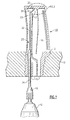
- FIG. 1 is illustrates a turbine blade in cross section that is mounted within a holding fixture and an elongated probe embodying the teachings of the invention is shown passing upwardly into a blade cavity through an opening in the blade root.
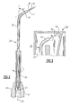
- FIG. 2 is an enlarged view in section of the upper part of the blade cavity showing the probe positioned adjacent a difficult to reach bend region;
- FIG. 3 is an enlarge side elevation in partial section further illustrating the probe of the present invention in greater detail.
- a turbine blade generally referenced 10, that has been removed from a jet engine.
- the root 12 of the blade is mounted within a holding fixture 13 arranged to securely hold the blade in a desired position while at the same time permitting free access to openings 15 leading to an internal cooling cavity 16 through the root of the blade.
- the cooling cavity as is typical in most turbine blades, follows a torturous path of travel having difficulty to reach regions such as the bend area 17 located in the top section of the blade. Normally, an unsupported straight length of flexible wire that is typically used to dislodge foreign matter 18 from the cavity will not be able to effectively penetrate this bend area.
- a probe or dislodging tool, generally referenced 20, that embodies the teachings of the present invention is illustrated in greater detail in Figs. 2 and 3.
- the probe includes an elongated tubular wire guide 22 that is capable of being inserted upwardly through a root opening in the blade.
- the guide is fabricated of a rigid material such as a length of stainless steel tubing.
- the guide is of sufficient length such that the guide can extend the full length of the entrance passage to a point adjacent to the hard to reach region 17 typically located at the top of the passage.
- the tip 24 of the guide is bent at an angle with regard to the axis 25 of guide so that the opening at the distal end of the guide can be directed at the hard to reach region.
- the length of the bend is relatively short so that the guide is able to move freely through cooling passage without snagging upon the passage wall. It has been found that an angle of about 30° at the tip of the guide works well in most blade applications. The angle may be adjusted, however, depending on the specific application.
- the lower section of the guide can be housed within a tubular sleeve 26 so that the sleeve can rotate about the axis of the guide.
- a close running fit may be provided between the outer wall of the guide and the inner wall of the sleeve so that the sleeve can turn freely about the axis of the guide without wobbling. It has been found that good results are realized when the sleeve extends upwardly from the bottom of the guide to about half way up the guide.
- a flexible metal wire 32 is passed upwardly through the center opening in the guide so that both the top end section 33 and the bottom end section 34 of the wire extend outwardly from both the distal and proximal ends of the guide.
- a close running fit is provided between the inner wall of the guide and the outer surface of the wire so that the wire can turn freely about the axis of the guide as well as being moved axially within the guide.
- the bottom section of the wire can be secured to the outer wall of the sleeve.
- the wire is turned around the bottom of the sleeve.
- the wire is held against the outer surface of the sleeve by means of an adjustable chuck 40 that is mounted upon a driver 42.
- the motor in practice may be battery driven or connected to a readily available mains outlet.
- the jaws 41 of the chuck are arranged to close over both the sleeve and the wire. Sufficient closing force is applied by the jaws to crimp the wire securely against the outer surface of the sleeve whereby both the wire and the sleeve can be rotated together at a desired speed.
- the guide is not turned as the chuck rotates and accordingly the distal end of the guide cap be directed into a hard to reach region.
- the wire is secured to the sleeve of by the jaw of an adjustable chuck in this embodiment of the invention, it should be clear that any suitable means for securing the wire to the sleeve can be employed without departing from the teachings of the present invention. Such techniques may involve welding or brazing the wire to the sleeve or simply wrapping the wire around the sleeve.
- the bent tip of the wire guide is brought adjacent to the hard to reach region and is pointed directly at the region.
- Sufficient wire is extended outwardly from the tip so that the wire will be able to contact any foreign material in this region.
- the cojoined wire and sleeve are then rotated at a relatively high speed to dislodge this unwanted material from the region and the dislodged material then be easily flushed from the cooling cavity.
- Positioning of the probe within the cooling cavity can be accomplished using well known x-ray imaging techniques.
Landscapes
- Engineering & Computer Science (AREA)
- Mechanical Engineering (AREA)
- Cleaning In General (AREA)
- Turbine Rotor Nozzle Sealing (AREA)
Abstract
Description
- This invention relates to efficiently dislodging foreign material from an internal cavity of an object such as a turbine blade and, in particular, to dislodging foreign material from hereto for relatively inaccessible regions inside an airfoil cavity.
- This invention relates to U.S. Patent
Application serial number 10/271,681 entitled Apparatus and Method for Cleaning Airfoil Internal Cavity, filed on October 15, 2002 and assigned to the assignee of the present invention and which is incorporated herein by reference. - The turbine blades found in most, if not all, jet engines in use today are cooled by passing a coolant through the interior of the blade. The coolant cavity typically has a torturous path of travel and may include one or more 180° turns. During use of the engine or repairs performed on the parts, foreign matter may enter the cavities of the engine blades and become adhered to the walls of the cavities, particularly in the hard to reach bend regions. In an effort to dislodge foreign matter from the walls of the blade cavities, metal wires of varying diameters are passed into the blade cavities through openings in the blade roots and the wire is turned at a speed that is sufficient high enough to dislodge any foreign material that it comes in contact with. This type of device works well in easy to reach locations. However, the wires cannot readily contact foreign matter that has lodged in the hard to reach areas. In addition, the flexible wire has a tendency to hang up on the walls of the cooling cavity making maneuvering of the probe rather difficult.
- It is therefore an object of the present invention to more thoroughly dislodge foreign material from an internal cavity of an object such as the cooling cavity of a turbine blade.
- It is a further object of the present invention to improve means for dislodging foreign matter from the internal cavity of an object.
- A still further object of the present invention is to provide a probe for dislodging foreign material that is located in hard to reach internal areas of an object.
- These and further objects of the present invention are attained by a probe having a wire that passes through a tubular guide so that the wire may be rotated within the guide. The distal end of the guide is bent at an angle whereby the guide can be inserted into an internal passage of an object and the wire directed into a hard to reach region to dislodge unwanted foreign material from the hard to reach region.
- For a better understanding of these and other objects of the invention, reference will be made to the following detailed description of the invention which is to be read in connection with the accompanying drawing, wherein:
- FIG. 1 is illustrates a turbine blade in cross section that is mounted within a holding fixture and an elongated probe embodying the teachings of the invention is shown passing upwardly into a blade cavity through an opening in the blade root.
- FIG. 2 is an enlarged view in section of the upper part of the blade cavity showing the probe positioned adjacent a difficult to reach bend region; and
- FIG. 3 is an enlarge side elevation in partial section further illustrating the probe of the present invention in greater detail.
- Turning now to the drawings there is illustrated in Fig. 1 a turbine blade, generally referenced 10, that has been removed from a jet engine. Although this disclosure will be made with specific reference to a jet engine turbine blade, it should be understood that the present invention can be utilized in association with any object containing an internal cavity that may entrap foreign material. The
root 12 of the blade is mounted within aholding fixture 13 arranged to securely hold the blade in a desired position while at the same time permitting free access toopenings 15 leading to aninternal cooling cavity 16 through the root of the blade. - The cooling cavity, as is typical in most turbine blades, follows a torturous path of travel having difficulty to reach regions such as the
bend area 17 located in the top section of the blade. Normally, an unsupported straight length of flexible wire that is typically used to dislodgeforeign matter 18 from the cavity will not be able to effectively penetrate this bend area. - A probe or dislodging tool, generally referenced 20, that embodies the teachings of the present invention is illustrated in greater detail in Figs. 2 and 3. The probe includes an elongated
tubular wire guide 22 that is capable of being inserted upwardly through a root opening in the blade. Preferably, the guide is fabricated of a rigid material such as a length of stainless steel tubing. The guide is of sufficient length such that the guide can extend the full length of the entrance passage to a point adjacent to the hard to reachregion 17 typically located at the top of the passage. Thetip 24 of the guide is bent at an angle with regard to theaxis 25 of guide so that the opening at the distal end of the guide can be directed at the hard to reach region. The length of the bend is relatively short so that the guide is able to move freely through cooling passage without snagging upon the passage wall. It has been found that an angle of about 30° at the tip of the guide works well in most blade applications. The angle may be adjusted, however, depending on the specific application. - The lower section of the guide can be housed within a
tubular sleeve 26 so that the sleeve can rotate about the axis of the guide. A close running fit may be provided between the outer wall of the guide and the inner wall of the sleeve so that the sleeve can turn freely about the axis of the guide without wobbling. It has been found that good results are realized when the sleeve extends upwardly from the bottom of the guide to about half way up the guide. Aflexible metal wire 32 is passed upwardly through the center opening in the guide so that both thetop end section 33 and the bottom end section 34 of the wire extend outwardly from both the distal and proximal ends of the guide. Here again a close running fit is provided between the inner wall of the guide and the outer surface of the wire so that the wire can turn freely about the axis of the guide as well as being moved axially within the guide. - The bottom section of the wire can be secured to the outer wall of the sleeve. As shown in Fig. 3, the wire is turned around the bottom of the sleeve. Preferably, the wire is held against the outer surface of the sleeve by means of an
adjustable chuck 40 that is mounted upon adriver 42. The motor in practice may be battery driven or connected to a readily available mains outlet. Thejaws 41 of the chuck are arranged to close over both the sleeve and the wire. Sufficient closing force is applied by the jaws to crimp the wire securely against the outer surface of the sleeve whereby both the wire and the sleeve can be rotated together at a desired speed. As can be seen, the guide is not turned as the chuck rotates and accordingly the distal end of the guide cap be directed into a hard to reach region. - Although the wire is secured to the sleeve of by the jaw of an adjustable chuck in this embodiment of the invention, it should be clear that any suitable means for securing the wire to the sleeve can be employed without departing from the teachings of the present invention. Such techniques may involve welding or brazing the wire to the sleeve or simply wrapping the wire around the sleeve.
- In the practice of the present invention, the bent tip of the wire guide is brought adjacent to the hard to reach region and is pointed directly at the region. Sufficient wire is extended outwardly from the tip so that the wire will be able to contact any foreign material in this region. The cojoined wire and sleeve are then rotated at a relatively high speed to dislodge this unwanted material from the region and the dislodged material then be easily flushed from the cooling cavity. Positioning of the probe within the cooling cavity can be accomplished using well known x-ray imaging techniques.
- While the present invention has been particularly shown and described with reference to the preferred mode as illustrated in the drawing, it will be understood by one skilled in the art that various changes in detail may be effected therein without departing from the spirit and scope of the invention as defined by the claims.
Claims (15)
- Apparatus for dislodging foreign material from a cavity of an object that includes:wherein the extended lower end of the wire is secured to said sleeve whereby the wire and the sleeve can rotate together about the axis of the guide.a tubular guide having a distal end and a proximal end such that the distal end of guide can be inserted into the interior cavity of said object;a tubular sleeve mounted over at least the lower portion of said guide so that said sleeve can rotate about the axis of said guide;a wire passing through said guide so that an upper end of the wire extends outwardly from the distal end of the guide and a lower portion of the wire extends outwardly from the proximal end of the guide; and
- The apparatus of claim 1 that includes further drive means for rotating said sleeve and said wire together.
- The apparatus of claim 2 wherein said means for securing said lower end of the wire to said sleeve is an adjustable chuck that is connected to said drive means, said chuck having jaws that are arranged to close over the sleeve and the wire to crimp the wire into engaging contact against the outside of said sleeve whereby the sleeve and the wire can be rotated together by said drive means.
- The apparatus of claim 3 wherein drive means is an electric motor.
- The apparatus of claim 1 wherein said wire forms a close running fit with the interior wall of said guide.
- The apparatus of claim 1 wherein said distal end of the guide is bent at an angle with relation to the axis of said guide.
- The apparatus of claim 6 wherein said distal end of the guide forms an angle of about 30° with said axis of said guide.
- The apparatus of claim 7 wherein the axial length of said sleeve is about half that of said guide.
- A method for dislodging foreign material from hard to reach regions of an object that includes the steps of:inserting a rigid tubular guide having a bent distal end tip into the object; directing the tip of the guide at a hard to reach region in said cavity;passing a wire through said guide so that the upper end of the wire can reside at the hard to reach region and the lower end of the wire extends outwardly from the proximal end of guide;rotatably mounting a portion of the guide within a tubular sleeve; andsecuring the lower end of the wire to the sleeve.
- The method of claim 9 that includes the further step of rotating the sleeve and the wire together about the axis of said guide.
- The method of claim 9 wherein the lower end of the wire is secured to the sleeve by closing the jaws of a chuck over the sleeve and the wire to crimp the wire against the sleeve.
- The method of claim 9 that further includes the step of mounting the object in a holding fixture.
- The method of claim 9 that includes the further step of bending the tip of the guide at the distal end thereof at an angle of about 30°.
- The method of claim 10 that includes the further step of connecting said chuck to a motorized driver for turning the chuck at a desired speed.
- An apparatus for dislodging foreign material from a hard to reach region of an object, comprising:wherein said guide has an angled portion at a distal end to direct said wire at said hard to reach region.a guide;a wire in said guide that is capable of rotation within said guide; and
Applications Claiming Priority (2)
| Application Number | Priority Date | Filing Date | Title |
|---|---|---|---|
| US801870 | 1997-02-18 | ||
| US10/801,870 US7146674B2 (en) | 2004-03-16 | 2004-03-16 | Rotary probe for cleaning an internal cavity |
Publications (2)
| Publication Number | Publication Date |
|---|---|
| EP1577027A1 true EP1577027A1 (en) | 2005-09-21 |
| EP1577027B1 EP1577027B1 (en) | 2010-06-16 |
Family
ID=34838896
Family Applications (1)
| Application Number | Title | Priority Date | Filing Date |
|---|---|---|---|
| EP05251600A Expired - Lifetime EP1577027B1 (en) | 2004-03-16 | 2005-03-16 | Rotary probe and method for cleaning an internal cavity |
Country Status (5)
| Country | Link |
|---|---|
| US (1) | US7146674B2 (en) |
| EP (1) | EP1577027B1 (en) |
| JP (1) | JP2005279642A (en) |
| DE (1) | DE602005021839D1 (en) |
| SG (1) | SG115764A1 (en) |
Cited By (2)
| Publication number | Priority date | Publication date | Assignee | Title |
|---|---|---|---|---|
| EP1891871A2 (en) | 2006-08-26 | 2008-02-27 | Bleuel, Norbert | Device for polishing, cleaning or drying the inside of a vessel for receiving liquids |
| CN102814309A (en) * | 2012-07-13 | 2012-12-12 | 马鞍山市双益机械制造有限公司 | Scale removing device for heat exchange pipe |
Families Citing this family (22)
| Publication number | Priority date | Publication date | Assignee | Title |
|---|---|---|---|---|
| WO2006041116A1 (en) * | 2004-10-14 | 2006-04-20 | Ichiro Sugimoto | Electric tooth brush |
| JP2007178191A (en) * | 2005-12-27 | 2007-07-12 | Toshiba Corp | High pressure cleaning device in the nozzle of nuclear reactor jet pump |
| US8312572B2 (en) * | 2006-10-05 | 2012-11-20 | Robert Scott Heffner | Telescoping plumbing device and method |
| FR2947633B1 (en) * | 2009-07-02 | 2012-04-13 | Snecma | DEVICE FOR NON-DESTRUCTIVE CONTROL OF A PIECE |
| JP5409725B2 (en) * | 2011-08-18 | 2014-02-05 | 学 枦山 | Small electric motor for cleaning brush |
| FR3070288B1 (en) * | 2017-08-31 | 2019-09-06 | Safran Landing Systems | METHOD FOR CLEARING PIPES IN PARTS OBTAINED BY ADDITIVE MANUFACTURING |
| US11707819B2 (en) | 2018-10-15 | 2023-07-25 | General Electric Company | Selectively flexible extension tool |
| US12194620B2 (en) | 2018-10-15 | 2025-01-14 | Oliver Crisipin Robotics Limited | Selectively flexible extension tool |
| US11702955B2 (en) | 2019-01-14 | 2023-07-18 | General Electric Company | Component repair system and method |
| US12405187B2 (en) | 2019-10-04 | 2025-09-02 | General Electric Company | Insertion apparatus for use with rotary machines |
| CN112610291A (en) * | 2019-10-04 | 2021-04-06 | 通用电气公司 | Insertion device for use with a rotary machine |
| US11692650B2 (en) | 2020-01-23 | 2023-07-04 | General Electric Company | Selectively flexible extension tool |
| US11752622B2 (en) | 2020-01-23 | 2023-09-12 | General Electric Company | Extension tool having a plurality of links |
| US11613003B2 (en) | 2020-01-24 | 2023-03-28 | General Electric Company | Line assembly for an extension tool having a plurality of links |
| US11371437B2 (en) | 2020-03-10 | 2022-06-28 | Oliver Crispin Robotics Limited | Insertion tool |
| US12091981B2 (en) | 2020-06-11 | 2024-09-17 | General Electric Company | Insertion tool and method |
| CN112454121B (en) * | 2020-11-04 | 2023-01-24 | 刘荣春 | But city wall adlet that multi-angle was adjusted grinds away equipment |
| US12416800B2 (en) | 2021-01-08 | 2025-09-16 | General Electric Company | Insertion tool |
| US12504616B2 (en) | 2021-01-08 | 2025-12-23 | General Electric Company | Insertion tool |
| US11654547B2 (en) | 2021-03-31 | 2023-05-23 | General Electric Company | Extension tool |
| US12031446B2 (en) * | 2022-03-29 | 2024-07-09 | General Electric Company | Turbine engine servicing tool and method for using thereof |
| CN115415260A (en) * | 2022-08-25 | 2022-12-02 | 淮北矿业股份有限公司 | Silt cleaning device of coal mine machinery |
Citations (2)
| Publication number | Priority date | Publication date | Assignee | Title |
|---|---|---|---|---|
| US5679174A (en) | 1995-10-27 | 1997-10-21 | Chromalloy Gas Turbine Corporation | Process and apparatus for cleaning gas turbine engine components |
| US6421871B1 (en) | 2001-03-16 | 2002-07-23 | Danny L. Peach | Pipe clearing apparatus |
Family Cites Families (10)
| Publication number | Priority date | Publication date | Assignee | Title |
|---|---|---|---|---|
| US507435A (en) * | 1893-10-24 | Waste-pipe-trap cleaner | ||
| US267306A (en) * | 1882-11-07 | John s | ||
| US984473A (en) * | 1910-11-05 | 1911-02-14 | Louis A Cornelius | Tool for removing obstructions in pipes. |
| US1851766A (en) * | 1930-08-16 | 1932-03-29 | Stow Mfg Company | Auger or boring device |
| JPH05329453A (en) * | 1992-05-28 | 1993-12-14 | Isao Shirayanagi | Cleaner for internal surface of bend |
| US5230116A (en) * | 1992-08-14 | 1993-07-27 | Jose Rodriguez | Anti-scratch toilet snake |
| US5769960A (en) * | 1995-07-05 | 1998-06-23 | Nirmel; Chittaranjan N. | Device and method for manually removing a clog containing fibrous matter |
| US6564823B1 (en) * | 1996-12-30 | 2003-05-20 | John M. Mankins | Method and apparatus for testing plumbing installations |
| US6094765A (en) * | 1998-07-06 | 2000-08-01 | Askenase; Matthew A. | Device for cleaning toilet bowls and other drains |
| US6920663B2 (en) * | 2001-09-21 | 2005-07-26 | Steven M. Petit | Tool for removing hair from a basin drain |
-
2004
- 2004-03-16 US US10/801,870 patent/US7146674B2/en not_active Expired - Fee Related
-
2005
- 2005-03-15 JP JP2005072413A patent/JP2005279642A/en active Pending
- 2005-03-16 EP EP05251600A patent/EP1577027B1/en not_active Expired - Lifetime
- 2005-03-16 DE DE602005021839T patent/DE602005021839D1/en not_active Expired - Lifetime
- 2005-03-16 SG SG200501605A patent/SG115764A1/en unknown
Patent Citations (2)
| Publication number | Priority date | Publication date | Assignee | Title |
|---|---|---|---|---|
| US5679174A (en) | 1995-10-27 | 1997-10-21 | Chromalloy Gas Turbine Corporation | Process and apparatus for cleaning gas turbine engine components |
| US6421871B1 (en) | 2001-03-16 | 2002-07-23 | Danny L. Peach | Pipe clearing apparatus |
Cited By (3)
| Publication number | Priority date | Publication date | Assignee | Title |
|---|---|---|---|---|
| EP1891871A2 (en) | 2006-08-26 | 2008-02-27 | Bleuel, Norbert | Device for polishing, cleaning or drying the inside of a vessel for receiving liquids |
| EP1891871A3 (en) * | 2006-08-26 | 2009-06-03 | Bleuel, Norbert | Device for polishing, cleaning or drying the inside of a vessel for receiving liquids |
| CN102814309A (en) * | 2012-07-13 | 2012-12-12 | 马鞍山市双益机械制造有限公司 | Scale removing device for heat exchange pipe |
Also Published As
| Publication number | Publication date |
|---|---|
| JP2005279642A (en) | 2005-10-13 |
| DE602005021839D1 (en) | 2010-07-29 |
| SG115764A1 (en) | 2005-10-28 |
| US7146674B2 (en) | 2006-12-12 |
| US20050204489A1 (en) | 2005-09-22 |
| EP1577027B1 (en) | 2010-06-16 |
Similar Documents
| Publication | Publication Date | Title |
|---|---|---|
| US7146674B2 (en) | Rotary probe for cleaning an internal cavity | |
| US6717092B2 (en) | Method of manufacturing treatment instrument of endoscope | |
| US5168660A (en) | Tubing abrasive cleaning device | |
| US5578056A (en) | Separable economically partially disposable flexible biopsy forceps | |
| JP4273039B2 (en) | Endoscopy forceps | |
| JP2002065598A (en) | Treatment instrument for endoscope | |
| CN117769400A (en) | Root canal sealing instruments | |
| FR2625429A1 (en) | Mechanised trocar, for performing surgical operations | |
| JP3533081B2 (en) | Connecting structure of flexible sheath of treatment device for endoscope | |
| JP2002346496A (en) | Apparatus and method for removing foreign matter | |
| JP5019723B2 (en) | Incision forceps | |
| JP2005131746A (en) | Polishing device of long pipe inside surface | |
| JP3175561B2 (en) | Ultrasonic probe | |
| JP4348089B2 (en) | Polishing device for inner surface of long pipe for steel tower | |
| KR100533509B1 (en) | In-search wire head for removing scale in pipe | |
| JPH10202427A (en) | Removing method for in-hole burr of curved pipe intermediate part and removing equipment therefor | |
| CN212547012U (en) | Cell brush capable of rotating in situ | |
| JP3934354B2 (en) | Endoscope bending instrument | |
| CN224088692U (en) | Polishing tool and polishing equipment | |
| JPS6127064Y2 (en) | ||
| CN117983566B (en) | Clip applier surface cleaning assembly, surface cleaning device and cleaning method | |
| JP2602486B2 (en) | Endoscope treatment instrument cleaning method and treatment instrument tip cap | |
| JP4619181B2 (en) | Endoscope automatic advance / retreat device | |
| JPH0347790Y2 (en) | ||
| JPH04138323U (en) | Brush device for cleaning |
Legal Events
| Date | Code | Title | Description |
|---|---|---|---|
| PUAI | Public reference made under article 153(3) epc to a published international application that has entered the european phase |
Free format text: ORIGINAL CODE: 0009012 |
|
| AK | Designated contracting states |
Kind code of ref document: A1 Designated state(s): AT BE BG CH CY CZ DE DK EE ES FI FR GB GR HU IE IS IT LI LT LU MC NL PL PT RO SE SI SK TR |
|
| AX | Request for extension of the european patent |
Extension state: AL BA HR LV MK YU |
|
| 17P | Request for examination filed |
Effective date: 20051007 |
|
| AKX | Designation fees paid |
Designated state(s): DE FR GB |
|
| 17Q | First examination report despatched |
Effective date: 20060718 |
|
| GRAP | Despatch of communication of intention to grant a patent |
Free format text: ORIGINAL CODE: EPIDOSNIGR1 |
|
| RIC1 | Information provided on ipc code assigned before grant |
Ipc: B08B 1/04 20060101AFI20091113BHEP Ipc: B08B 9/00 20060101ALI20091113BHEP Ipc: F01D 25/00 20060101ALI20091113BHEP Ipc: B08B 9/087 20060101ALI20091113BHEP |
|
| RTI1 | Title (correction) |
Free format text: ROTARY PROBE AND METHOD FOR CLEANING AN INTERNAL CAVITY |
|
| GRAS | Grant fee paid |
Free format text: ORIGINAL CODE: EPIDOSNIGR3 |
|
| GRAA | (expected) grant |
Free format text: ORIGINAL CODE: 0009210 |
|
| AK | Designated contracting states |
Kind code of ref document: B1 Designated state(s): DE FR GB |
|
| REF | Corresponds to: |
Ref document number: 602005021839 Country of ref document: DE Date of ref document: 20100729 Kind code of ref document: P |
|
| PLBE | No opposition filed within time limit |
Free format text: ORIGINAL CODE: 0009261 |
|
| STAA | Information on the status of an ep patent application or granted ep patent |
Free format text: STATUS: NO OPPOSITION FILED WITHIN TIME LIMIT |
|
| 26N | No opposition filed |
Effective date: 20110317 |
|
| REG | Reference to a national code |
Ref country code: DE Ref legal event code: R097 Ref document number: 602005021839 Country of ref document: DE Effective date: 20110316 |
|
| REG | Reference to a national code |
Ref country code: FR Ref legal event code: ST Effective date: 20111130 |
|
| PG25 | Lapsed in a contracting state [announced via postgrant information from national office to epo] |
Ref country code: FR Free format text: LAPSE BECAUSE OF NON-PAYMENT OF DUE FEES Effective date: 20110331 |
|
| PGFP | Annual fee paid to national office [announced via postgrant information from national office to epo] |
Ref country code: DE Payment date: 20130314 Year of fee payment: 9 Ref country code: GB Payment date: 20130313 Year of fee payment: 9 |
|
| REG | Reference to a national code |
Ref country code: DE Ref legal event code: R119 Ref document number: 602005021839 Country of ref document: DE |
|
| GBPC | Gb: european patent ceased through non-payment of renewal fee |
Effective date: 20140316 |
|
| REG | Reference to a national code |
Ref country code: DE Ref legal event code: R119 Ref document number: 602005021839 Country of ref document: DE Effective date: 20141001 |
|
| PG25 | Lapsed in a contracting state [announced via postgrant information from national office to epo] |
Ref country code: DE Free format text: LAPSE BECAUSE OF NON-PAYMENT OF DUE FEES Effective date: 20141001 Ref country code: GB Free format text: LAPSE BECAUSE OF NON-PAYMENT OF DUE FEES Effective date: 20140316 |