EP1575725B1 - Vibratory spiral conveyor - Google Patents
Vibratory spiral conveyor Download PDFInfo
- Publication number
- EP1575725B1 EP1575725B1 EP03814379A EP03814379A EP1575725B1 EP 1575725 B1 EP1575725 B1 EP 1575725B1 EP 03814379 A EP03814379 A EP 03814379A EP 03814379 A EP03814379 A EP 03814379A EP 1575725 B1 EP1575725 B1 EP 1575725B1
- Authority
- EP
- European Patent Office
- Prior art keywords
- conveyor
- air
- housing
- spiral
- deck
- Prior art date
- Legal status (The legal status is an assumption and is not a legal conclusion. Google has not performed a legal analysis and makes no representation as to the accuracy of the status listed.)
- Expired - Lifetime
Links
- 238000004891 communication Methods 0.000 claims abstract description 5
- 239000012530 fluid Substances 0.000 claims abstract description 5
- 238000005266 casting Methods 0.000 description 10
- 239000002245 particle Substances 0.000 description 6
- 239000004576 sand Substances 0.000 description 3
- 238000001816 cooling Methods 0.000 description 2
- 229910000746 Structural steel Inorganic materials 0.000 description 1
- 230000009286 beneficial effect Effects 0.000 description 1
- 230000009977 dual effect Effects 0.000 description 1
- 239000008187 granular material Substances 0.000 description 1
- 238000010438 heat treatment Methods 0.000 description 1
- 238000002955 isolation Methods 0.000 description 1
- 239000000463 material Substances 0.000 description 1
- 238000000034 method Methods 0.000 description 1
- 238000000465 moulding Methods 0.000 description 1
Images
Classifications
-
- F—MECHANICAL ENGINEERING; LIGHTING; HEATING; WEAPONS; BLASTING
- F26—DRYING
- F26B—DRYING SOLID MATERIALS OR OBJECTS BY REMOVING LIQUID THEREFROM
- F26B17/00—Machines or apparatus for drying materials in loose, plastic, or fluidised form, e.g. granules, staple fibres, with progressive movement
- F26B17/26—Machines or apparatus for drying materials in loose, plastic, or fluidised form, e.g. granules, staple fibres, with progressive movement with movement performed by reciprocating or oscillating conveyors propelling materials over stationary surfaces; with movement performed by reciprocating or oscillating shelves, sieves, or trays
- F26B17/266—Machines or apparatus for drying materials in loose, plastic, or fluidised form, e.g. granules, staple fibres, with progressive movement with movement performed by reciprocating or oscillating conveyors propelling materials over stationary surfaces; with movement performed by reciprocating or oscillating shelves, sieves, or trays the materials to be dried being moved in a helical, spiral or circular path, e.g. vibrated helix
-
- B—PERFORMING OPERATIONS; TRANSPORTING
- B22—CASTING; POWDER METALLURGY
- B22D—CASTING OF METALS; CASTING OF OTHER SUBSTANCES BY THE SAME PROCESSES OR DEVICES
- B22D30/00—Cooling castings, not restricted to casting processes covered by a single main group
Definitions
- the present disclosure generally relates to vibratory process equipment and, more particularly, to vibratory spiral conveyors for transporting work pieces in a helical path.
- Vibratory spiral conveyors are generally known in the art.
- Such apparatus typically includes a spiral deck, formed in the shape of a helix, and a source of vibration operatively coupled to the deck.
- the spiral conveyor may be a brute force system, such as that disclosed in U.S. Patent No. 2,927,683 to Carrier , or a two-mass system, as disclosed in U.S. Patent No. 5,024,320 to Musschoot .
- JP-A-10 339 571 discloses a vibratory spiral conveyor type dryer with hot air entering via an internal cylinder.
- Spiral conveyors are often used to heat or cool work pieces or granular material.
- red hot castings which may have a temperature of approximately 537°C (1000 degrees F) or more
- Cool air is directed over the castings as the castings travel up the spiral, thereby to reduce the temperature of the castings.
- Conventional spiral conveyors direct air from a center axis of the conveyor outwardly, with or without nozzles for directing the air toward the castings. The air is exhausted out an exterior of the spiral conveyor.
- air is generally directed radially across the spiral conveyor from the center core inlets to the outer periphery outlets.
- the inner facing side of the castings or the inner row, should more than one row of castings be fed into the conveyor) will receive a lower temperature air than the outer facing side (or outer row).
- both the air inlet and air outlet are positioned at the outer periphery of the spiral conveyor. As the air enters the spiral conveyor area, it passes about the center core in at least two separate sub-streams. The air then exhausts from the spiral conveyor through a common outlet.
- the castings can include foundry sand that may become entrained in the cooling air stream.
- foundry sand that may become entrained in the cooling air stream.
- very light particles such as small grains of sand or sprue, are picked up by the air stream. Consequently, a filter house is typically connected to the outlet air stream to collect the particles before the air is exhausted to atmosphere.
- the filter house is typically provided as a separate unit, and is located outside of the spiral conveyor, thereby requiring additional space for the conveying equipment.
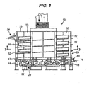
- a vibratory spiral conveyor 10 as set forth in claim 1 having a frame 12 supporting a spiral deck 16.
- the word spiral includes helix and helicoid shapes.
- the frame 12 is resiliently supported above the ground or mounting surface by isolation means, such as springs 18.
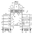
- An exciter mass 20 and vibration generators 22 are resiliently coupled to the trough frame 12, such as by springs 25 ( FIG. 2 ). Any generally known vibration generators may be used, such as motors having rotating shafts carrying eccentric weights.
- a housing 15 is provided for enclosing the spiral deck 16 and defining a conveyor chamber 17.
- the spiral deck includes an inner edge 19 and an outer edge 21.
- the housing 15 has a cylindrical inner wall 38 coupled to the spiral deck inner edge 19 and a cylindrical outer wall 50 coupled to the spiral deck outer edge 21.
- the housing 15 may also include a top wall 23 ( FIG. 2 ), so that the housing 15 completely encloses the spiral deck 16 but for a housing inlet 24 and outlet 26. Accordingly, the housing 15 and spiral deck 16 define the conveyor chamber 17, which has a spiral configuration in the illustrated embodiment.
- a plurality of access doors 52 ( FIG. 1 ) may be formed in the housing outer wall 50 for accessing the conveyor chamber 17 and deck 16.
- the spiral deck 16 is oriented to vertically elevate work pieces, such as hot castings, from the inlet 24 to the outlet 26.
- the work pieces may be transferred from an origination point, such as a molding line, to the inlet 24 by any conveying means, such as by a linear vibratory or other type of conveyor (not shown).
- the spiral deck 16 is formed in a helical pattern so that, as the work pieces move circumferentially around the deck, they are also elevated in the vertical direction.
- the work piece may be deposited onto an outlet transport (not shown), which may also be a conveyor. While the conveyor 10 is described herein as conveying the work pieces vertically upward, the inlet and outlet may be reversed so that the work pieces are conveyed vertically downward along the spiral deck 16.
- the spiral deck 16 When viewed in elevational cross-section, as shown in FIG. 2 , the spiral deck 16 defines a plurality of stacked tier segments 14.
- the tier segments 14 are vertically aligned so that adjacent tier segments 14 define upper and lower boundaries of a cross-sectional area of the conveyor chamber 17.
- the vibration generators 22 may be controlled in any known fashion to produce the desired vibrational motion of the trough frame 12 and coupled spiral deck 16 to advance the work pieces along the deck 16.
- the motors may be rotated in opposite directions (i.e., counter-rotated) and controlled to maintain a desired phase angle between the eccentric weights. While the illustrated embodiment is a two mass system, it will be appreciated that the conveyor 10 may be provided as a single mass or brute force system.
- a plenum housing 29 defines an inlet air plenum 30 formed near a top of the spiral deck 16 and within a central chamber 56 defined by the housing inner wall 38.
- a pair of air inlet ducts 32 is connected to the plenum housing 29 by flexible joints 34.
- a single inlet duct 32 or more than two inlet ducts 32 may communicate with the inlet air plenum 30.
- Extending downwardly from the inlet air plenum 30 is a plurality of vertical air conduits 36.
- the housing inner wall 38 forms outer portions of each conduit 36, while concave chamber walls 40 form a remainder of each conduit 36.
- a plurality of air distribution chambers 42 is attached to a bottom side of the spiral deck 16 and communicates with each vertical air conduit 36.
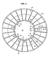
- the air distribution chambers may be oriented to extend generally horizontally and, as best shown in FIG. 3 , may be aligned generally radially between the housing inner wall 38 and housing outer wall 50.
- a pair of air distribution chambers 42 on each spiral deck tier portion 14 fluidly communicates with a respective vertical air conduit 36.
- each air conduit 36 may fluidly communicate with a single air distribution chamber 42 or more than two air distribution chambers 42 on each spiral deck tier portion 14. While FIG. 3 illustrates a single tier portion 14 of the spiral deck 16, it will be appreciated that similar sets of air distribution chambers 42 may be constructed on each of the spiral deck tier segments 14, so that each conduit 36 may communicate with multiple vertical levels of air distribution chambers 42.
- Each air distribution chamber 42 includes a plurality of spaced nozzles 44 oriented to direct air flow downwardly toward the next lower tier.
- the nozzles 44 may be apertures formed in a bottom of the air distribution chambers 42.
- the apertures are arranged across at least a portion of a lateral width "W" of the spiral deck 16 to form an air distribution pattern. In the illustrated embodiment, the apertures are generally equally spaced across the entire lateral width "W" of the spiral deck 16.
- the vertical air conduits 36 and horizontal air chambers 42 may be formed of structural steel members, such as channels and angles, to provide structural support to the spiral conveyor 10. In this case, the conduits 36 and chambers 42 provide the dual functions of air distribution and structural support.
- the vibratory conveyor 10 further provides for exhaust of air out of the conveyor chamber.
- a plurality of outlet openings 54 are formed in the housing inner wall 38, each opening 54 being positioned between adjacent vertical air conduits 36.
- the outlet openings 54 fluidly communicate with the central chamber 56 defined by the housing inner wall.
- An air exhaust outlet 58 fluidly communicates with the central chamber 56 and is coupled, such as by flexible joint 60, to exhaust duct 62.
- the exhaust duct 62 may communicate with an air vacuum source 63 (schematically illustrated in FIG. 2 ), soch as ain exhaust fan, to create air flow through the air distribution system.
- the plenum housing 29 has a generally annular shape, so that an inner edge 31 of the plenum housing 29 defines the exhaust outlet 58.
- the air vacuum source pulls air through the inlet ducts 32 to the inlet air plenum 30.
- the air stream flows from the plenum through the air conduits 36 and air distribution chambers 42 for discharge through the nozzles 44, which evenly distribute air across the entire lateral width "W" of the spiral deck 16.
- the air vacuum source is preferably sized so that the air stream discharged from each nozzle 44 has a velocity sufficiently high to create non-laminar flow around the work pieces. By creating a non-laminar air flow, the heat transfer coefficient for the system is increased, thereby increasing heat transfer, which is beneficial for both heating and cooling applications.
- the air exits the conveyor chamber 17 through the outlet openings 54 and into the central chamber 56, where it is discharged through the exhaust outlet 58.
- the conveyor 10 may include a fines collection system for collecting any fines entrained in the air stream passing through the conveyor chamber 17.
- the objects or work pieces loaded into the conveyor 10 may include unwanted debris, such as sand, sprue, or other fines material.
- the fines collection system may include a catch floor 70 extending across a bottom of the central chamber 56 and coupled to the housing 15 below the lowest outlet opening 54.
- the catch floor includes a conical center portion 72 attached to a frusto-conical outer portion 74.
- a fines discharge opening 76 is formed at an outer periphery of the outer portion 74 and communicates with a fines discharge chute 78 ( FIG. 1 ).
- the discharge opening communicates with atmosphere via the chute 78, and therefore the negative pressure in the central chamber 56 creates a pressure differential that tends to hold the fines within the chamber 56.
- an air lock 80 may be provided in the chute 78 to allow and control discharge of fines through the chute.
- air is discharged from the nozzles 44 at a relatively high velocity, so that fines may become dislodged from the work pieces and entrained in the air stream.
- the air stream then passes through the outlet openings 54, which causes a pressure drop and associated reduction in velocity of the air stream as it enters the central chamber 56.
- the reduced velocity causes the fines entrained in the air stream to drop to the catch floor 70.
- the vibratory motion of the spiral deck 16 and attached catch floor 70 moves the particles toward an outer periphery of the catch floor outer portion 74.
- the circular component of the vibratory motion conveys the particles circumferentially about the floor periphery until the particles reach the discharge opening 76, at which point they travel down the discharge chute 78 and into the air lock 80.
- the air lock 80 may be operated to periodically interrupt fluid communication between the chute 78 and the central chamber 56, thereby to allow a batch of fines to be discharged from the chute 78 for collection.
- the fines collection system utilizes the existing internal structure of the spiral conveyor to collect and discharge particles entrained in the air stream. As a result, separate filter houses are not required and the space required for spiral conveyor apparatus is reduced.
Landscapes
- Engineering & Computer Science (AREA)
- Mechanical Engineering (AREA)
- General Engineering & Computer Science (AREA)
- Jigging Conveyors (AREA)
- Structure Of Belt Conveyors (AREA)
- Screw Conveyors (AREA)
- Belt Conveyors (AREA)
- Fish Paste Products (AREA)
Applications Claiming Priority (3)
| Application Number | Priority Date | Filing Date | Title |
|---|---|---|---|
| US43635202P | 2002-12-23 | 2002-12-23 | |
| US436352P | 2002-12-23 | ||
| PCT/US2003/041235 WO2004058602A2 (en) | 2002-12-23 | 2003-12-23 | Vibratory spiral conveyor |
Publications (2)
| Publication Number | Publication Date |
|---|---|
| EP1575725A2 EP1575725A2 (en) | 2005-09-21 |
| EP1575725B1 true EP1575725B1 (en) | 2009-12-16 |
Family
ID=32682381
Family Applications (1)
| Application Number | Title | Priority Date | Filing Date |
|---|---|---|---|
| EP03814379A Expired - Lifetime EP1575725B1 (en) | 2002-12-23 | 2003-12-23 | Vibratory spiral conveyor |
Country Status (10)
| Country | Link |
|---|---|
| US (3) | US7037048B2 (pl) |
| EP (1) | EP1575725B1 (pl) |
| JP (1) | JP4230459B2 (pl) |
| AT (1) | ATE451990T1 (pl) |
| AU (1) | AU2003297524B2 (pl) |
| BR (1) | BR0317620B1 (pl) |
| CA (1) | CA2511033A1 (pl) |
| DE (1) | DE60330597D1 (pl) |
| PL (1) | PL376069A1 (pl) |
| WO (1) | WO2004058602A2 (pl) |
Families Citing this family (15)
| Publication number | Priority date | Publication date | Assignee | Title |
|---|---|---|---|---|
| EP1575725B1 (en) * | 2002-12-23 | 2009-12-16 | General Kinematics Corporation | Vibratory spiral conveyor |
| US7487868B2 (en) * | 2003-12-23 | 2009-02-10 | General Kinematics Corporation | Vibratory conveyor deck with adjustable curvature |
| EP1902796A1 (en) * | 2004-08-25 | 2008-03-26 | General Kinematics Corporation | Vibratory spiral conveyor |
| US7296951B2 (en) * | 2004-08-25 | 2007-11-20 | General Kinematics Corporation | Vibratory spiral conveyor |
| DE102005013055B4 (de) * | 2005-03-18 | 2007-02-08 | Jöst GmbH + Co. KG | Wendelkühler |
| WO2011091111A1 (en) | 2010-01-22 | 2011-07-28 | The Iams Company | Process for making a pet food in the form of a coated kibble |
| MY180796A (en) * | 2011-09-02 | 2020-12-09 | First Solar Inc | Feeder system and method for a vapor transport deposition system |
| FR2983186B1 (fr) * | 2011-11-24 | 2014-01-17 | Technical Alliance | Dispositif de transport vibrant helicoidal |
| US9950870B2 (en) * | 2012-01-20 | 2018-04-24 | Mayfran International | Vertical spiral conveyor |
| CA2982836A1 (en) | 2015-04-28 | 2016-11-03 | Mars, Incorporated | Process of preparing a sterilized wet pet food product |
| AU2016289709B2 (en) | 2015-07-03 | 2019-10-31 | Dumbaugh, George D | Vibrating screening feeder and method of use |
| US9919882B2 (en) * | 2016-01-06 | 2018-03-20 | Oren Technologies, Llc | Conveyor with integrated dust collector system |
| US10046916B1 (en) | 2017-02-14 | 2018-08-14 | General Kinematics Corporation | Vibratory apparatus with structural resilient member |
| WO2020236821A1 (en) * | 2019-05-20 | 2020-11-26 | General Kinematics Corporation | Vibratory drum with circular motion |
| RU2736389C1 (ru) * | 2020-01-10 | 2020-11-16 | Акционерное общество "Научно-производственный центр "ВНИИ комбикормовой промышленности" (АО "НПЦ "ВНИИКП") | Сушилка |
Citations (1)
| Publication number | Priority date | Publication date | Assignee | Title |
|---|---|---|---|---|
| JPH10339571A (ja) * | 1997-06-09 | 1998-12-22 | Mitsubishi Heavy Ind Ltd | 乾燥装置 |
Family Cites Families (23)
| Publication number | Priority date | Publication date | Assignee | Title |
|---|---|---|---|---|
| US2927683A (en) | 1957-12-26 | 1960-03-08 | Carrier Conveyor Corp | Drive for a helical vibratory conveyor |
| US3664487A (en) * | 1969-05-23 | 1972-05-23 | Carl H Ballenger | Endless helical conveyer and belt |
| US3850288A (en) | 1969-07-22 | 1974-11-26 | Gen Kinematics Corp | Vertical lift conveyor |
| DE2037371C3 (de) | 1969-07-22 | 1975-05-28 | General Kinematics Corp., Barrington, Ill. (V.St.A.) | Vertikalschwingförderer zum Befördern eines stückigen oder körnigen Materials |
| US3789977A (en) | 1972-01-14 | 1974-02-05 | Gen Kinematics Corp | Vibratory vertical lift conveyor |
| US4140215A (en) | 1974-08-05 | 1979-02-20 | General Kinematics Corporation | Method of achieving vertical lift of particulate material |
| US4140288A (en) * | 1978-05-10 | 1979-02-20 | Champion International Corporation | Method for splicing plastic sheet materials |
| US4775288A (en) * | 1986-10-03 | 1988-10-04 | Dynamic Industries, Inc. | High-lift loader |
| US4775284A (en) | 1986-12-02 | 1988-10-04 | General Kinematics Corporation | Vertical mass flow conveyor |
| EP0287860A3 (en) * | 1987-03-31 | 1989-06-07 | Asmo Co., Ltd. | Mechanism converting rotary motion into reciprocating motion |
| US5024320A (en) | 1987-05-08 | 1991-06-18 | General Kinematics Corporation | Vibratory spiral elevator |
| US4875343A (en) * | 1988-03-14 | 1989-10-24 | Jeppsson E Hakan O | Climate chamber with conveyor |
| US4953365A (en) * | 1989-06-28 | 1990-09-04 | Liquid Carbonic Corporation | Helical conveyor freezer |
| GB2235756A (en) | 1989-09-05 | 1991-03-13 | Star Refrigeration | Helical refrigeration apparatus |
| DE4106712C1 (en) * | 1991-03-02 | 1992-06-25 | Joest Gmbh + Co Kg, 4408 Duelmen, De | Spiral conveyor with vibration drive - has tubular guide above conveyed material, whose gas outlets forming slit, pointing downwards to material |
| US5413213A (en) * | 1992-07-25 | 1995-05-09 | Korber Ag | Apparatus for transporting mass flows of articles |
| DE4228543C1 (de) * | 1992-08-27 | 1993-11-25 | Joest Gmbh & Co Kg | Mittels eines Schwingantriebes angetriebener Wendelförderer |
| US6418834B1 (en) * | 1999-07-26 | 2002-07-16 | Paul M. Perrine | Apparatus for treating an item during travel of the item along a treating trough |
| US6948611B2 (en) * | 1999-07-30 | 2005-09-27 | Kinergy Corporation | Vibratory conveying apparatus adapted to be driven by accumulatively phased rotating eccentric weights |
| EP1575725B1 (en) * | 2002-12-23 | 2009-12-16 | General Kinematics Corporation | Vibratory spiral conveyor |
| US6827201B1 (en) * | 2003-06-12 | 2004-12-07 | General Kinematics Corporation | Vibratory feeder for transporting objects in a curved path |
| US7296951B2 (en) * | 2004-08-25 | 2007-11-20 | General Kinematics Corporation | Vibratory spiral conveyor |
| DE102005062715B4 (de) * | 2005-12-28 | 2008-02-14 | Fette Gmbh | Vorrichtung zum Befüllen von Aufnahmebehältern mit den Produkten einer Rundläuferpresse |
-
2003
- 2003-12-23 EP EP03814379A patent/EP1575725B1/en not_active Expired - Lifetime
- 2003-12-23 PL PL03376069A patent/PL376069A1/pl unknown
- 2003-12-23 DE DE60330597T patent/DE60330597D1/de not_active Expired - Lifetime
- 2003-12-23 US US10/745,228 patent/US7037048B2/en not_active Expired - Lifetime
- 2003-12-23 CA CA002511033A patent/CA2511033A1/en not_active Abandoned
- 2003-12-23 JP JP2004564042A patent/JP4230459B2/ja not_active Expired - Fee Related
- 2003-12-23 WO PCT/US2003/041235 patent/WO2004058602A2/en not_active Ceased
- 2003-12-23 AT AT03814379T patent/ATE451990T1/de not_active IP Right Cessation
- 2003-12-23 AU AU2003297524A patent/AU2003297524B2/en not_active Expired
- 2003-12-23 BR BRPI0317620-7A patent/BR0317620B1/pt active IP Right Grant
-
2006
- 2006-03-01 US US11/365,362 patent/US7377728B2/en not_active Expired - Lifetime
-
2008
- 2008-05-27 US US12/127,549 patent/US7540694B2/en not_active Expired - Lifetime
Patent Citations (1)
| Publication number | Priority date | Publication date | Assignee | Title |
|---|---|---|---|---|
| JPH10339571A (ja) * | 1997-06-09 | 1998-12-22 | Mitsubishi Heavy Ind Ltd | 乾燥装置 |
Also Published As
| Publication number | Publication date |
|---|---|
| CA2511033A1 (en) | 2004-07-15 |
| US20040168889A1 (en) | 2004-09-02 |
| US20080226400A1 (en) | 2008-09-18 |
| DE60330597D1 (de) | 2010-01-28 |
| US7037048B2 (en) | 2006-05-02 |
| JP4230459B2 (ja) | 2009-02-25 |
| AU2003297524A1 (en) | 2004-07-22 |
| JP2006511414A (ja) | 2006-04-06 |
| ATE451990T1 (de) | 2010-01-15 |
| US7377728B2 (en) | 2008-05-27 |
| WO2004058602A3 (en) | 2004-08-26 |
| US20060147277A1 (en) | 2006-07-06 |
| BR0317620A (pt) | 2005-11-29 |
| EP1575725A2 (en) | 2005-09-21 |
| PL376069A1 (pl) | 2005-12-12 |
| AU2003297524B2 (en) | 2008-08-14 |
| WO2004058602A2 (en) | 2004-07-15 |
| BR0317620B1 (pt) | 2011-10-18 |
| US7540694B2 (en) | 2009-06-02 |
Similar Documents
| Publication | Publication Date | Title |
|---|---|---|
| US7540694B2 (en) | Vibratory conveyor | |
| US20070297863A1 (en) | Vibratory spiral conveyor | |
| TWI794258B (zh) | 振動烘乾裝置 | |
| CN101606035B (zh) | 用于排除流体和/或固体的设备 | |
| US8813966B2 (en) | Pneumatic vacuum separation plant for bulk materials | |
| JP7746027B2 (ja) | 粉末をスクリーニングするための装置及び方法 | |
| JPH05506808A (ja) | 中間段分離器 | |
| US5406718A (en) | Method and apparatus for drying particulate material | |
| US5243767A (en) | Method and apparatus for processing particulate material | |
| JP4330204B2 (ja) | 原料加熱装置 | |
| EP0383896B1 (en) | Apparatus for pneumatic transportation of particulate material such as tobacco | |
| JP6821278B1 (ja) | 分離装置 | |
| JP3420099B2 (ja) | 廃棄物選別装置 | |
| CN214638132U (zh) | 一种具有多级回收的谷糙分离设备 | |
| EP1902796A1 (en) | Vibratory spiral conveyor | |
| EP0031379A1 (en) | Dehydration equipment | |
| JPH1133384A (ja) | 連続造粒・コーティング方法及びその装置 | |
| US4432412A (en) | Cooling device | |
| RU2408440C1 (ru) | Устройство для разделения порошкообразных материалов по крупности | |
| US916757A (en) | Centrifugal grain-cleaner. | |
| SU1491573A1 (ru) | Вибрационна мельница | |
| WO2021152663A1 (ja) | 砂製造装置、砂研磨装置、及び砂分級装置 | |
| JPH0560575U (ja) | 粉粒体分離器 | |
| KR20170121634A (ko) | 재순환 주물사의 냉각장치 |
Legal Events
| Date | Code | Title | Description |
|---|---|---|---|
| PUAI | Public reference made under article 153(3) epc to a published international application that has entered the european phase |
Free format text: ORIGINAL CODE: 0009012 |
|
| 17P | Request for examination filed |
Effective date: 20050610 |
|
| AK | Designated contracting states |
Kind code of ref document: A2 Designated state(s): AT BE BG CH CY CZ DE DK EE ES FI FR GB GR HU IE IT LI LU MC NL PT RO SE SI SK TR |
|
| AX | Request for extension of the european patent |
Extension state: AL LT LV MK |
|
| DAX | Request for extension of the european patent (deleted) | ||
| 17Q | First examination report despatched |
Effective date: 20070115 |
|
| R17C | First examination report despatched (corrected) |
Effective date: 20070115 |
|
| GRAP | Despatch of communication of intention to grant a patent |
Free format text: ORIGINAL CODE: EPIDOSNIGR1 |
|
| GRAS | Grant fee paid |
Free format text: ORIGINAL CODE: EPIDOSNIGR3 |
|
| GRAJ | Information related to disapproval of communication of intention to grant by the applicant or resumption of examination proceedings by the epo deleted |
Free format text: ORIGINAL CODE: EPIDOSDIGR1 |
|
| GRAP | Despatch of communication of intention to grant a patent |
Free format text: ORIGINAL CODE: EPIDOSNIGR1 |
|
| GRAS | Grant fee paid |
Free format text: ORIGINAL CODE: EPIDOSNIGR3 |
|
| GRAA | (expected) grant |
Free format text: ORIGINAL CODE: 0009210 |
|
| AK | Designated contracting states |
Kind code of ref document: B1 Designated state(s): AT BE BG CH CY CZ DE DK EE ES FI FR GB GR HU IE IT LI LU MC NL PT RO SE SI SK TR |
|
| REG | Reference to a national code |
Ref country code: GB Ref legal event code: FG4D |
|
| REG | Reference to a national code |
Ref country code: CH Ref legal event code: EP |
|
| REG | Reference to a national code |
Ref country code: IE Ref legal event code: FG4D |
|
| REF | Corresponds to: |
Ref document number: 60330597 Country of ref document: DE Date of ref document: 20100128 Kind code of ref document: P |
|
| REG | Reference to a national code |
Ref country code: CH Ref legal event code: NV Representative=s name: HEPP WENGER RYFFEL AG |
|
| REG | Reference to a national code |
Ref country code: NL Ref legal event code: VDEP Effective date: 20091216 |
|
| PG25 | Lapsed in a contracting state [announced via postgrant information from national office to epo] |
Ref country code: FI Free format text: LAPSE BECAUSE OF FAILURE TO SUBMIT A TRANSLATION OF THE DESCRIPTION OR TO PAY THE FEE WITHIN THE PRESCRIBED TIME-LIMIT Effective date: 20091216 Ref country code: SE Free format text: LAPSE BECAUSE OF FAILURE TO SUBMIT A TRANSLATION OF THE DESCRIPTION OR TO PAY THE FEE WITHIN THE PRESCRIBED TIME-LIMIT Effective date: 20091216 |
|
| PG25 | Lapsed in a contracting state [announced via postgrant information from national office to epo] |
Ref country code: SI Free format text: LAPSE BECAUSE OF FAILURE TO SUBMIT A TRANSLATION OF THE DESCRIPTION OR TO PAY THE FEE WITHIN THE PRESCRIBED TIME-LIMIT Effective date: 20091216 |
|
| PG25 | Lapsed in a contracting state [announced via postgrant information from national office to epo] |
Ref country code: AT Free format text: LAPSE BECAUSE OF FAILURE TO SUBMIT A TRANSLATION OF THE DESCRIPTION OR TO PAY THE FEE WITHIN THE PRESCRIBED TIME-LIMIT Effective date: 20091216 |
|
| PG25 | Lapsed in a contracting state [announced via postgrant information from national office to epo] |
Ref country code: BG Free format text: LAPSE BECAUSE OF FAILURE TO SUBMIT A TRANSLATION OF THE DESCRIPTION OR TO PAY THE FEE WITHIN THE PRESCRIBED TIME-LIMIT Effective date: 20100316 Ref country code: NL Free format text: LAPSE BECAUSE OF FAILURE TO SUBMIT A TRANSLATION OF THE DESCRIPTION OR TO PAY THE FEE WITHIN THE PRESCRIBED TIME-LIMIT Effective date: 20091216 Ref country code: RO Free format text: LAPSE BECAUSE OF FAILURE TO SUBMIT A TRANSLATION OF THE DESCRIPTION OR TO PAY THE FEE WITHIN THE PRESCRIBED TIME-LIMIT Effective date: 20091216 Ref country code: PT Free format text: LAPSE BECAUSE OF FAILURE TO SUBMIT A TRANSLATION OF THE DESCRIPTION OR TO PAY THE FEE WITHIN THE PRESCRIBED TIME-LIMIT Effective date: 20100416 Ref country code: ES Free format text: LAPSE BECAUSE OF FAILURE TO SUBMIT A TRANSLATION OF THE DESCRIPTION OR TO PAY THE FEE WITHIN THE PRESCRIBED TIME-LIMIT Effective date: 20100327 Ref country code: MC Free format text: LAPSE BECAUSE OF NON-PAYMENT OF DUE FEES Effective date: 20100701 Ref country code: EE Free format text: LAPSE BECAUSE OF FAILURE TO SUBMIT A TRANSLATION OF THE DESCRIPTION OR TO PAY THE FEE WITHIN THE PRESCRIBED TIME-LIMIT Effective date: 20091216 |
|
| PG25 | Lapsed in a contracting state [announced via postgrant information from national office to epo] |
Ref country code: BE Free format text: LAPSE BECAUSE OF FAILURE TO SUBMIT A TRANSLATION OF THE DESCRIPTION OR TO PAY THE FEE WITHIN THE PRESCRIBED TIME-LIMIT Effective date: 20091216 Ref country code: SK Free format text: LAPSE BECAUSE OF FAILURE TO SUBMIT A TRANSLATION OF THE DESCRIPTION OR TO PAY THE FEE WITHIN THE PRESCRIBED TIME-LIMIT Effective date: 20091216 Ref country code: CZ Free format text: LAPSE BECAUSE OF FAILURE TO SUBMIT A TRANSLATION OF THE DESCRIPTION OR TO PAY THE FEE WITHIN THE PRESCRIBED TIME-LIMIT Effective date: 20091216 |
|
| PLBE | No opposition filed within time limit |
Free format text: ORIGINAL CODE: 0009261 |
|
| STAA | Information on the status of an ep patent application or granted ep patent |
Free format text: STATUS: NO OPPOSITION FILED WITHIN TIME LIMIT |
|
| PG25 | Lapsed in a contracting state [announced via postgrant information from national office to epo] |
Ref country code: GR Free format text: LAPSE BECAUSE OF FAILURE TO SUBMIT A TRANSLATION OF THE DESCRIPTION OR TO PAY THE FEE WITHIN THE PRESCRIBED TIME-LIMIT Effective date: 20100317 Ref country code: IE Free format text: LAPSE BECAUSE OF NON-PAYMENT OF DUE FEES Effective date: 20091223 Ref country code: CY Free format text: LAPSE BECAUSE OF FAILURE TO SUBMIT A TRANSLATION OF THE DESCRIPTION OR TO PAY THE FEE WITHIN THE PRESCRIBED TIME-LIMIT Effective date: 20091216 |
|
| 26N | No opposition filed |
Effective date: 20100917 |
|
| PG25 | Lapsed in a contracting state [announced via postgrant information from national office to epo] |
Ref country code: DK Free format text: LAPSE BECAUSE OF FAILURE TO SUBMIT A TRANSLATION OF THE DESCRIPTION OR TO PAY THE FEE WITHIN THE PRESCRIBED TIME-LIMIT Effective date: 20091216 |
|
| PG25 | Lapsed in a contracting state [announced via postgrant information from national office to epo] |
Ref country code: LU Free format text: LAPSE BECAUSE OF NON-PAYMENT OF DUE FEES Effective date: 20091223 |
|
| PG25 | Lapsed in a contracting state [announced via postgrant information from national office to epo] |
Ref country code: HU Free format text: LAPSE BECAUSE OF FAILURE TO SUBMIT A TRANSLATION OF THE DESCRIPTION OR TO PAY THE FEE WITHIN THE PRESCRIBED TIME-LIMIT Effective date: 20100617 |
|
| PG25 | Lapsed in a contracting state [announced via postgrant information from national office to epo] |
Ref country code: TR Free format text: LAPSE BECAUSE OF FAILURE TO SUBMIT A TRANSLATION OF THE DESCRIPTION OR TO PAY THE FEE WITHIN THE PRESCRIBED TIME-LIMIT Effective date: 20091216 |
|
| REG | Reference to a national code |
Ref country code: FR Ref legal event code: PLFP Year of fee payment: 13 |
|
| REG | Reference to a national code |
Ref country code: FR Ref legal event code: PLFP Year of fee payment: 14 |
|
| REG | Reference to a national code |
Ref country code: FR Ref legal event code: PLFP Year of fee payment: 15 |
|
| PGFP | Annual fee paid to national office [announced via postgrant information from national office to epo] |
Ref country code: GB Payment date: 20221222 Year of fee payment: 20 Ref country code: FR Payment date: 20221222 Year of fee payment: 20 Ref country code: DE Payment date: 20221213 Year of fee payment: 20 |
|
| PGFP | Annual fee paid to national office [announced via postgrant information from national office to epo] |
Ref country code: CH Payment date: 20230103 Year of fee payment: 20 |
|
| PGFP | Annual fee paid to national office [announced via postgrant information from national office to epo] |
Ref country code: IT Payment date: 20221228 Year of fee payment: 20 |
|
| P01 | Opt-out of the competence of the unified patent court (upc) registered |
Effective date: 20230411 |
|
| REG | Reference to a national code |
Ref country code: DE Ref legal event code: R071 Ref document number: 60330597 Country of ref document: DE |
|
| REG | Reference to a national code |
Ref country code: CH Ref legal event code: PL |
|
| REG | Reference to a national code |
Ref country code: GB Ref legal event code: PE20 Expiry date: 20231222 |
|
| PG25 | Lapsed in a contracting state [announced via postgrant information from national office to epo] |
Ref country code: GB Free format text: LAPSE BECAUSE OF EXPIRATION OF PROTECTION Effective date: 20231222 |
|
| PG25 | Lapsed in a contracting state [announced via postgrant information from national office to epo] |
Ref country code: GB Free format text: LAPSE BECAUSE OF EXPIRATION OF PROTECTION Effective date: 20231222 |