EP1575698B1 - Method for generation of a synthesis gas mixture co/h sb 2 /sb under pressure by catalytic partial oxidation with minimisation of the formation of soot - Google Patents
Method for generation of a synthesis gas mixture co/h sb 2 /sb under pressure by catalytic partial oxidation with minimisation of the formation of soot Download PDFInfo
- Publication number
- EP1575698B1 EP1575698B1 EP03812078A EP03812078A EP1575698B1 EP 1575698 B1 EP1575698 B1 EP 1575698B1 EP 03812078 A EP03812078 A EP 03812078A EP 03812078 A EP03812078 A EP 03812078A EP 1575698 B1 EP1575698 B1 EP 1575698B1
- Authority
- EP
- European Patent Office
- Prior art keywords
- hydrogen
- cooling
- gas
- gas mixture
- carried out
- Prior art date
- Legal status (The legal status is an assumption and is not a legal conclusion. Google has not performed a legal analysis and makes no representation as to the accuracy of the status listed.)
- Expired - Lifetime
Links
- 239000000203 mixture Substances 0.000 title claims abstract description 60
- 238000000034 method Methods 0.000 title claims abstract description 49
- 238000007254 oxidation reaction Methods 0.000 title claims abstract description 21
- 230000003197 catalytic effect Effects 0.000 title claims abstract description 19
- 230000003647 oxidation Effects 0.000 title claims abstract description 13
- 239000004071 soot Substances 0.000 title claims description 6
- 230000015572 biosynthetic process Effects 0.000 title description 9
- 238000003786 synthesis reaction Methods 0.000 title description 5
- 239000001257 hydrogen Substances 0.000 claims abstract description 69
- 229910052739 hydrogen Inorganic materials 0.000 claims abstract description 69
- 239000007789 gas Substances 0.000 claims abstract description 61
- UFHFLCQGNIYNRP-UHFFFAOYSA-N Hydrogen Chemical compound [H][H] UFHFLCQGNIYNRP-UHFFFAOYSA-N 0.000 claims abstract description 48
- 238000001816 cooling Methods 0.000 claims abstract description 36
- XLYOFNOQVPJJNP-UHFFFAOYSA-N water Substances O XLYOFNOQVPJJNP-UHFFFAOYSA-N 0.000 claims abstract description 36
- UGFAIRIUMAVXCW-UHFFFAOYSA-N Carbon monoxide Chemical compound [O+]#[C-] UGFAIRIUMAVXCW-UHFFFAOYSA-N 0.000 claims abstract description 26
- 229910002091 carbon monoxide Inorganic materials 0.000 claims abstract description 25
- 229930195733 hydrocarbon Natural products 0.000 claims abstract description 22
- 150000002430 hydrocarbons Chemical class 0.000 claims abstract description 22
- 238000006243 chemical reaction Methods 0.000 claims abstract description 18
- 239000004215 Carbon black (E152) Substances 0.000 claims abstract description 17
- 238000009434 installation Methods 0.000 claims abstract description 16
- 238000004519 manufacturing process Methods 0.000 claims description 35
- VNWKTOKETHGBQD-UHFFFAOYSA-N methane Chemical compound C VNWKTOKETHGBQD-UHFFFAOYSA-N 0.000 claims description 35
- IJGRMHOSHXDMSA-UHFFFAOYSA-N Atomic nitrogen Chemical compound N#N IJGRMHOSHXDMSA-UHFFFAOYSA-N 0.000 claims description 23
- 150000002431 hydrogen Chemical class 0.000 claims description 21
- QVGXLLKOCUKJST-UHFFFAOYSA-N atomic oxygen Chemical compound [O] QVGXLLKOCUKJST-UHFFFAOYSA-N 0.000 claims description 16
- 239000001301 oxygen Substances 0.000 claims description 16
- 229910052760 oxygen Inorganic materials 0.000 claims description 16
- 238000000926 separation method Methods 0.000 claims description 13
- CURLTUGMZLYLDI-UHFFFAOYSA-N Carbon dioxide Chemical compound O=C=O CURLTUGMZLYLDI-UHFFFAOYSA-N 0.000 claims description 11
- 229910052751 metal Inorganic materials 0.000 claims description 10
- 239000002184 metal Substances 0.000 claims description 10
- 239000003054 catalyst Substances 0.000 claims description 9
- OTMSDBZUPAUEDD-UHFFFAOYSA-N Ethane Chemical compound CC OTMSDBZUPAUEDD-UHFFFAOYSA-N 0.000 claims description 8
- ATUOYWHBWRKTHZ-UHFFFAOYSA-N Propane Chemical compound CCC ATUOYWHBWRKTHZ-UHFFFAOYSA-N 0.000 claims description 8
- 229910002092 carbon dioxide Inorganic materials 0.000 claims description 8
- 239000012528 membrane Substances 0.000 claims description 8
- 239000003345 natural gas Substances 0.000 claims description 8
- 229910052757 nitrogen Inorganic materials 0.000 claims description 8
- 239000002699 waste material Substances 0.000 claims description 8
- PXHVJJICTQNCMI-UHFFFAOYSA-N Nickel Chemical compound [Ni] PXHVJJICTQNCMI-UHFFFAOYSA-N 0.000 claims description 6
- KDLHZDBZIXYQEI-UHFFFAOYSA-N Palladium Chemical compound [Pd] KDLHZDBZIXYQEI-UHFFFAOYSA-N 0.000 claims description 6
- 238000006555 catalytic reaction Methods 0.000 claims description 6
- 239000000498 cooling water Substances 0.000 claims description 6
- 239000012535 impurity Substances 0.000 claims description 6
- 230000001133 acceleration Effects 0.000 claims description 5
- BASFCYQUMIYNBI-UHFFFAOYSA-N platinum Chemical compound [Pt] BASFCYQUMIYNBI-UHFFFAOYSA-N 0.000 claims description 5
- 239000001273 butane Substances 0.000 claims description 4
- 238000001914 filtration Methods 0.000 claims description 4
- IJDNQMDRQITEOD-UHFFFAOYSA-N n-butane Chemical compound CCCC IJDNQMDRQITEOD-UHFFFAOYSA-N 0.000 claims description 4
- OFBQJSOFQDEBGM-UHFFFAOYSA-N n-pentane Natural products CCCCC OFBQJSOFQDEBGM-UHFFFAOYSA-N 0.000 claims description 4
- 239000001294 propane Substances 0.000 claims description 4
- 230000005611 electricity Effects 0.000 claims description 3
- 150000002739 metals Chemical class 0.000 claims description 3
- 229910052759 nickel Inorganic materials 0.000 claims description 3
- 230000001590 oxidative effect Effects 0.000 claims description 3
- 229910052763 palladium Inorganic materials 0.000 claims description 3
- 229910052703 rhodium Inorganic materials 0.000 claims description 3
- 239000010948 rhodium Substances 0.000 claims description 3
- MHOVAHRLVXNVSD-UHFFFAOYSA-N rhodium atom Chemical compound [Rh] MHOVAHRLVXNVSD-UHFFFAOYSA-N 0.000 claims description 3
- 239000000956 alloy Substances 0.000 claims description 2
- 229910045601 alloy Inorganic materials 0.000 claims description 2
- 239000001569 carbon dioxide Substances 0.000 claims description 2
- MWUXSHHQAYIFBG-UHFFFAOYSA-N nitrogen oxide Inorganic materials O=[N] MWUXSHHQAYIFBG-UHFFFAOYSA-N 0.000 claims description 2
- 239000002245 particle Substances 0.000 claims description 2
- 238000005371 permeation separation Methods 0.000 claims description 2
- 229910052697 platinum Inorganic materials 0.000 claims description 2
- 230000008929 regeneration Effects 0.000 claims description 2
- 238000011069 regeneration method Methods 0.000 claims description 2
- 239000002912 waste gas Substances 0.000 claims 3
- QJGQUHMNIGDVPM-UHFFFAOYSA-N nitrogen group Chemical group [N] QJGQUHMNIGDVPM-UHFFFAOYSA-N 0.000 claims 2
- 230000003134 recirculating effect Effects 0.000 claims 1
- 239000007787 solid Substances 0.000 claims 1
- 239000008246 gaseous mixture Substances 0.000 abstract description 19
- 238000010791 quenching Methods 0.000 abstract description 8
- 230000000171 quenching effect Effects 0.000 abstract description 7
- 238000011084 recovery Methods 0.000 abstract description 2
- 230000000694 effects Effects 0.000 abstract 1
- 238000002360 preparation method Methods 0.000 abstract 1
- OKKJLVBELUTLKV-UHFFFAOYSA-N Methanol Chemical compound OC OKKJLVBELUTLKV-UHFFFAOYSA-N 0.000 description 12
- 230000004907 flux Effects 0.000 description 9
- FAPWRFPIFSIZLT-UHFFFAOYSA-M Sodium chloride Chemical compound [Na+].[Cl-] FAPWRFPIFSIZLT-UHFFFAOYSA-M 0.000 description 7
- QGZKDVFQNNGYKY-UHFFFAOYSA-N Ammonia Chemical compound N QGZKDVFQNNGYKY-UHFFFAOYSA-N 0.000 description 6
- 239000000047 product Substances 0.000 description 6
- 238000002485 combustion reaction Methods 0.000 description 5
- 229910052799 carbon Inorganic materials 0.000 description 4
- 229910021529 ammonia Inorganic materials 0.000 description 3
- 229940059082 douche Drugs 0.000 description 3
- 238000002407 reforming Methods 0.000 description 3
- 239000011780 sodium chloride Substances 0.000 description 3
- 239000000243 solution Substances 0.000 description 3
- 238000000629 steam reforming Methods 0.000 description 3
- 238000010744 Boudouard reaction Methods 0.000 description 2
- XEEYBQQBJWHFJM-UHFFFAOYSA-N Iron Chemical compound [Fe] XEEYBQQBJWHFJM-UHFFFAOYSA-N 0.000 description 2
- 241001080024 Telles Species 0.000 description 2
- 230000015556 catabolic process Effects 0.000 description 2
- 239000003153 chemical reaction reagent Substances 0.000 description 2
- 239000000571 coke Substances 0.000 description 2
- 238000006731 degradation reaction Methods 0.000 description 2
- 238000005868 electrolysis reaction Methods 0.000 description 2
- 238000002347 injection Methods 0.000 description 2
- 239000007924 injection Substances 0.000 description 2
- 238000012423 maintenance Methods 0.000 description 2
- 239000000376 reactant Substances 0.000 description 2
- 238000007670 refining Methods 0.000 description 2
- 238000001179 sorption measurement Methods 0.000 description 2
- 229910000831 Steel Inorganic materials 0.000 description 1
- 240000008042 Zea mays Species 0.000 description 1
- 230000003466 anti-cipated effect Effects 0.000 description 1
- 238000013459 approach Methods 0.000 description 1
- 238000004523 catalytic cracking Methods 0.000 description 1
- 238000001833 catalytic reforming Methods 0.000 description 1
- 238000000354 decomposition reaction Methods 0.000 description 1
- 238000006356 dehydrogenation reaction Methods 0.000 description 1
- 238000006477 desulfuration reaction Methods 0.000 description 1
- 230000023556 desulfurization Effects 0.000 description 1
- 238000009826 distribution Methods 0.000 description 1
- 238000010410 dusting Methods 0.000 description 1
- 230000005592 electrolytic dissociation Effects 0.000 description 1
- 229940082150 encore Drugs 0.000 description 1
- 238000005516 engineering process Methods 0.000 description 1
- 230000007613 environmental effect Effects 0.000 description 1
- 239000003344 environmental pollutant Substances 0.000 description 1
- 239000000446 fuel Substances 0.000 description 1
- 125000004435 hydrogen atom Chemical group [H]* 0.000 description 1
- 238000005984 hydrogenation reaction Methods 0.000 description 1
- 239000011810 insulating material Substances 0.000 description 1
- 229910052742 iron Inorganic materials 0.000 description 1
- 239000012263 liquid product Substances 0.000 description 1
- 238000005272 metallurgy Methods 0.000 description 1
- 229910000510 noble metal Inorganic materials 0.000 description 1
- VIKNJXKGJWUCNN-XGXHKTLJSA-N norethisterone Chemical compound O=C1CC[C@@H]2[C@H]3CC[C@](C)([C@](CC4)(O)C#C)[C@@H]4[C@@H]3CCC2=C1 VIKNJXKGJWUCNN-XGXHKTLJSA-N 0.000 description 1
- 239000003208 petroleum Substances 0.000 description 1
- 235000012830 plain croissants Nutrition 0.000 description 1
- 231100000719 pollutant Toxicity 0.000 description 1
- 238000010944 pre-mature reactiony Methods 0.000 description 1
- 238000000746 purification Methods 0.000 description 1
- 238000004064 recycling Methods 0.000 description 1
- 238000005507 spraying Methods 0.000 description 1
- 239000010959 steel Substances 0.000 description 1
- 238000003860 storage Methods 0.000 description 1
- 238000004227 thermal cracking Methods 0.000 description 1
- 238000007669 thermal treatment Methods 0.000 description 1
- 230000001988 toxicity Effects 0.000 description 1
- 231100000419 toxicity Toxicity 0.000 description 1
Images
Classifications
-
- B—PERFORMING OPERATIONS; TRANSPORTING
- B01—PHYSICAL OR CHEMICAL PROCESSES OR APPARATUS IN GENERAL
- B01J—CHEMICAL OR PHYSICAL PROCESSES, e.g. CATALYSIS OR COLLOID CHEMISTRY; THEIR RELEVANT APPARATUS
- B01J8/00—Chemical or physical processes in general, conducted in the presence of fluids and solid particles; Apparatus for such processes
- B01J8/02—Chemical or physical processes in general, conducted in the presence of fluids and solid particles; Apparatus for such processes with stationary particles, e.g. in fixed beds
- B01J8/04—Chemical or physical processes in general, conducted in the presence of fluids and solid particles; Apparatus for such processes with stationary particles, e.g. in fixed beds the fluid passing successively through two or more beds
- B01J8/0446—Chemical or physical processes in general, conducted in the presence of fluids and solid particles; Apparatus for such processes with stationary particles, e.g. in fixed beds the fluid passing successively through two or more beds the flow within the beds being predominantly vertical
- B01J8/0449—Chemical or physical processes in general, conducted in the presence of fluids and solid particles; Apparatus for such processes with stationary particles, e.g. in fixed beds the fluid passing successively through two or more beds the flow within the beds being predominantly vertical in two or more cylindrical beds
- B01J8/0453—Chemical or physical processes in general, conducted in the presence of fluids and solid particles; Apparatus for such processes with stationary particles, e.g. in fixed beds the fluid passing successively through two or more beds the flow within the beds being predominantly vertical in two or more cylindrical beds the beds being superimposed one above the other
-
- B—PERFORMING OPERATIONS; TRANSPORTING
- B01—PHYSICAL OR CHEMICAL PROCESSES OR APPARATUS IN GENERAL
- B01J—CHEMICAL OR PHYSICAL PROCESSES, e.g. CATALYSIS OR COLLOID CHEMISTRY; THEIR RELEVANT APPARATUS
- B01J8/00—Chemical or physical processes in general, conducted in the presence of fluids and solid particles; Apparatus for such processes
- B01J8/008—Details of the reactor or of the particulate material; Processes to increase or to retard the rate of reaction
-
- C—CHEMISTRY; METALLURGY
- C01—INORGANIC CHEMISTRY
- C01B—NON-METALLIC ELEMENTS; COMPOUNDS THEREOF; METALLOIDS OR COMPOUNDS THEREOF NOT COVERED BY SUBCLASS C01C
- C01B3/00—Hydrogen; Gaseous mixtures containing hydrogen; Separation of hydrogen from mixtures containing it; Purification of hydrogen
- C01B3/02—Production of hydrogen or of gaseous mixtures containing a substantial proportion of hydrogen
- C01B3/32—Production of hydrogen or of gaseous mixtures containing a substantial proportion of hydrogen by reaction of gaseous or liquid organic compounds with gasifying agents, e.g. water, carbon dioxide, air
- C01B3/34—Production of hydrogen or of gaseous mixtures containing a substantial proportion of hydrogen by reaction of gaseous or liquid organic compounds with gasifying agents, e.g. water, carbon dioxide, air by reaction of hydrocarbons with gasifying agents
- C01B3/38—Production of hydrogen or of gaseous mixtures containing a substantial proportion of hydrogen by reaction of gaseous or liquid organic compounds with gasifying agents, e.g. water, carbon dioxide, air by reaction of hydrocarbons with gasifying agents using catalysts
- C01B3/386—Catalytic partial combustion
-
- B—PERFORMING OPERATIONS; TRANSPORTING
- B01—PHYSICAL OR CHEMICAL PROCESSES OR APPARATUS IN GENERAL
- B01J—CHEMICAL OR PHYSICAL PROCESSES, e.g. CATALYSIS OR COLLOID CHEMISTRY; THEIR RELEVANT APPARATUS
- B01J2208/00—Processes carried out in the presence of solid particles; Reactors therefor
- B01J2208/00008—Controlling the process
- B01J2208/00017—Controlling the temperature
- B01J2208/00327—Controlling the temperature by direct heat exchange
- B01J2208/00336—Controlling the temperature by direct heat exchange adding a temperature modifying medium to the reactants
- B01J2208/00353—Non-cryogenic fluids
- B01J2208/00362—Liquid
-
- B—PERFORMING OPERATIONS; TRANSPORTING
- B01—PHYSICAL OR CHEMICAL PROCESSES OR APPARATUS IN GENERAL
- B01J—CHEMICAL OR PHYSICAL PROCESSES, e.g. CATALYSIS OR COLLOID CHEMISTRY; THEIR RELEVANT APPARATUS
- B01J2208/00—Processes carried out in the presence of solid particles; Reactors therefor
- B01J2208/00008—Controlling the process
- B01J2208/00017—Controlling the temperature
- B01J2208/00477—Controlling the temperature by thermal insulation means
- B01J2208/00495—Controlling the temperature by thermal insulation means using insulating materials or refractories
-
- C—CHEMISTRY; METALLURGY
- C01—INORGANIC CHEMISTRY
- C01B—NON-METALLIC ELEMENTS; COMPOUNDS THEREOF; METALLOIDS OR COMPOUNDS THEREOF NOT COVERED BY SUBCLASS C01C
- C01B2203/00—Integrated processes for the production of hydrogen or synthesis gas
- C01B2203/02—Processes for making hydrogen or synthesis gas
- C01B2203/025—Processes for making hydrogen or synthesis gas containing a partial oxidation step
- C01B2203/0261—Processes for making hydrogen or synthesis gas containing a partial oxidation step containing a catalytic partial oxidation step [CPO]
-
- C—CHEMISTRY; METALLURGY
- C01—INORGANIC CHEMISTRY
- C01B—NON-METALLIC ELEMENTS; COMPOUNDS THEREOF; METALLOIDS OR COMPOUNDS THEREOF NOT COVERED BY SUBCLASS C01C
- C01B2203/00—Integrated processes for the production of hydrogen or synthesis gas
- C01B2203/02—Processes for making hydrogen or synthesis gas
- C01B2203/0266—Processes for making hydrogen or synthesis gas containing a decomposition step
- C01B2203/0277—Processes for making hydrogen or synthesis gas containing a decomposition step containing a catalytic decomposition step
-
- C—CHEMISTRY; METALLURGY
- C01—INORGANIC CHEMISTRY
- C01B—NON-METALLIC ELEMENTS; COMPOUNDS THEREOF; METALLOIDS OR COMPOUNDS THEREOF NOT COVERED BY SUBCLASS C01C
- C01B2203/00—Integrated processes for the production of hydrogen or synthesis gas
- C01B2203/04—Integrated processes for the production of hydrogen or synthesis gas containing a purification step for the hydrogen or the synthesis gas
- C01B2203/0405—Purification by membrane separation
-
- C—CHEMISTRY; METALLURGY
- C01—INORGANIC CHEMISTRY
- C01B—NON-METALLIC ELEMENTS; COMPOUNDS THEREOF; METALLOIDS OR COMPOUNDS THEREOF NOT COVERED BY SUBCLASS C01C
- C01B2203/00—Integrated processes for the production of hydrogen or synthesis gas
- C01B2203/08—Methods of heating or cooling
- C01B2203/0872—Methods of cooling
- C01B2203/0877—Methods of cooling by direct injection of fluid
-
- C—CHEMISTRY; METALLURGY
- C01—INORGANIC CHEMISTRY
- C01B—NON-METALLIC ELEMENTS; COMPOUNDS THEREOF; METALLOIDS OR COMPOUNDS THEREOF NOT COVERED BY SUBCLASS C01C
- C01B2203/00—Integrated processes for the production of hydrogen or synthesis gas
- C01B2203/12—Feeding the process for making hydrogen or synthesis gas
- C01B2203/1205—Composition of the feed
- C01B2203/1211—Organic compounds or organic mixtures used in the process for making hydrogen or synthesis gas
- C01B2203/1235—Hydrocarbons
- C01B2203/1241—Natural gas or methane
-
- C—CHEMISTRY; METALLURGY
- C01—INORGANIC CHEMISTRY
- C01B—NON-METALLIC ELEMENTS; COMPOUNDS THEREOF; METALLOIDS OR COMPOUNDS THEREOF NOT COVERED BY SUBCLASS C01C
- C01B2203/00—Integrated processes for the production of hydrogen or synthesis gas
- C01B2203/80—Aspect of integrated processes for the production of hydrogen or synthesis gas not covered by groups C01B2203/02 - C01B2203/1695
- C01B2203/84—Energy production
Definitions
- the present invention relates to the field of processes for producing a gaseous mixture containing at least hydrogen (H 2 ) and carbon monoxide (CO) from at least one hydrocarbon, in which catalytic oxidation is carried out portion of at least one hydrocarbon in the presence of oxygen or an oxygen-containing gas to produce a mixture of hydrogen and carbon monoxide.
- H 2 hydrogen
- CO carbon monoxide
- Hydrogen is a gas widely used especially in the field of chemistry.
- the global annual production of hydrogen is of the order of 50 billion m 3, of which 95% is used in refining, in petrochemistry, for the synthesis of methanol (MeOH) or for the production of ammonia (NH 3 ).
- PSA Pressure Swing Adsorption
- the energy efficiency of such a process is excellent, that is to say up to 85% for large installations by valuing the fatal vapor.
- ammonia (NH 3 ) is a harmful pollutant for the environment (toxicity, odor, ...) and regulations on this product are becoming more severe.
- the technical solution proposed according to the present invention then consists in carrying out the partial oxidation reaction and the quenching of the product gas (in this case a direct quenching with water) in a single enclosure, by carrying out a transport time.
- gas between the two zones which is extremely low, ie less than a few tens of milliseconds, typically less than 50 ms.
- This rapid quenching (we can say instantaneous or almost instantaneous) will make it possible to instantly freeze the composition of the gas and limit the Boudouard reaction (2 CO ⁇ C + CO 2 ) and thus the generation of soot harmful to the process.
- said cooling means comprise a shower of water in which passes the mixture to be cooled.
- the installation comprises a deflector system, located downstream of the cooling means, adapted to separate the drops of water to prevent them from being entrained by the cooled gas.
- the installation comprises a device for supplying and re-circulating the cooling water under pressure, preferably equipped with a cooling water filtration system. under pressure.
- the installation comprises an inverted cone system located between the two zones of catalytic and cooling reaction, able to allow the acceleration of the gaseous mixture obtained at the outlet of the reactor between said two reaction and cooling zones.
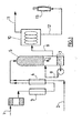
- FIG. 1 shows a catalytic reactor 5 supplied with air 1 (preheated through a heater 3 and with natural gas 2, the mixture being produced at the mixer 4.
- the partial catalytic oxidation (5) is carried out at a temperature below 1200 ° C., at a pressure of 3 to 20 bars, and a gaseous mixture containing hydrogen (H 2 ) and hydrogen is recovered at 6. carbon monoxide (CO).
- This gas mixture is subjected in 7 to quenching with water to a temperature between -20 ° C and + 80 ° C.
- the mixture thus cooled is then subjected to a "PSA" type separation step in order to produce a hydrogen-rich gas stream at a pressure in the range of 3 to 20 bars.
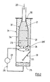
- the mixture 20 of hydrocarbon and oxidizing gas encounters for the embodiment represented here, successively, within a refractory casing 32, a zone of inert balls 21 , a catalyst zone 22, then another inert zone 23.
- the mixture thus obtained (as comprising hydrogen and CO) immediately approaches a cooling zone here consisting of a shower (spraying) of water 24.
- the reactor 32 and the cooling means are located in a single enclosure 31 (metal shell), so as to achieve a gas transport time between the two zones of catalytic reaction and cooling which either very low, in this case less than a few tens of milliseconds.
- the reactor is isolated therefrom by the presence of a thermal insulating material 34.
Abstract
Description
La présente invention concerne le domaine des procédés de production d'un mélange gazeux contenant au moins de l'hydrogène (H2) et du monoxyde de carbone (CO) à partir d'au moins un hydrocarbure, dans lequel on opère une oxydation catalytique partielle d'au moins un hydrocarbure, en présence d'oxygène ou d'un gaz contenant de l'oxygène, pour produire un mélange d'hydrogène et du monoxyde de carbone.The present invention relates to the field of processes for producing a gaseous mixture containing at least hydrogen (H 2 ) and carbon monoxide (CO) from at least one hydrocarbon, in which catalytic oxidation is carried out portion of at least one hydrocarbon in the presence of oxygen or an oxygen-containing gas to produce a mixture of hydrogen and carbon monoxide.
L'hydrogène est un gaz largement utilisé notamment dans le domaine de la chimie.Hydrogen is a gas widely used especially in the field of chemistry.
Ainsi, la production annuelle globale d'hydrogène est de l'ordre de 50 milliards de m3 dont 95 % sont utilisés en raffinage, en pétrochimie, pour la synthèse de méthanol (MeOH) ou encore pour la production d'ammoniac (NH3).Thus, the global annual production of hydrogen is of the order of 50 billion m 3, of which 95% is used in refining, in petrochemistry, for the synthesis of methanol (MeOH) or for the production of ammonia (NH 3 ).
L'hydrogène marchand, c'est-à-dire la production non captive, ne représente donc que quelques pour cents de cette production globale.Merchantable hydrogen, that is to say, non-captive production, represents only a few percent of this total production.
Or, compte tenu des besoins croissants en hydrogène marchand, de l'ordre d'environ + 10 % par an, et des futurs besoins pressentis dans l'industrie en général, notamment en chimie, en pétrochimie, en métallurgie, en électronique, en chimie fine, dans la production d'énergie décentralisée, des transports propres et non polluants, en utilisant les piles à combustible, et compte tenu des problèmes soulevés par l'infrastructure de distribution de ce produit, en particulier son transport, son stockage et les problèmes de sécurité qui y sont liés, il apparaît de plus en plus nécessaire de disposer de sources de production directement sur le site ("on site") d'utilisation.However, in view of the growing needs for merchantable hydrogen, of the order of about + 10% per year, and of the anticipated future needs in the industry in general, in particular in chemistry, petrochemistry, metallurgy, electronics, fine chemistry, in the production of decentralized energy, clean and non-polluting transport, using fuel cells, and taking into account the problems raised by the distribution infrastructure of this product, in particular its transport, its storage and the related security problems, it is increasingly necessary to have production sources directly on the site ("on site") of use.
La production d'hydrogène en grande quantité se fait principalement chez les raffineurs et les grands chimistes par différentes méthodes connues, à savoir :
- --> par reformage à la vapeur d'eau des hydrocarbures d'origine pétrolière (naphta) ou du gaz naturel. C'est une réaction très endothermique, effectuée entre 800°C et 900°C avec un ou des catalyseurs et à haute pression, par exemple de l'ordre de 15 bars à 35 bars. Les brûleurs sont situés à l'extérieur des lits catalytiques et le mélange hydrocarbures/vapeur est préchauffé grâce à des échangeurs de chaleur qui utilisent les gaz chauds de combustion. Ce procédé permet d'atteindre des rapports de production H2/CO entre 3 et 4 suivant le débit de vapeur.
- ---> par reformage mixte : c'est un procédé auto-thermique où l'énergie thermique nécessaire au reformage à la vapeur sur catalyseur est par exemple apportée par la combustion partielle de CH4 en CO2 et H2O. Par contre, le rapport H2/CO est plus faible que lors d'une production par reformage à la vapeur d'eau, c'est-à-dire de l'ordre de 2.2 à 2.5.
- ---> par oxydation partielle d'hydrocarbures. Ce procédé ne nécessite pas de catalyseur. La réaction est effectuée entre 1300°C et 1400°C avec peu ou sans vapeur. Ce procédé est exothermique mais produit moins d'hydrogène que les procédés précédents. C'est pourquoi il est nécessaire de favoriser au maximum la réaction de production d'hydrogène par conversion du CO en présence de vapeur d'eau et sur catalyseur, selon la réaction (1) suivante (dite « réaction du gaz à l'eau ») :
CO + H2O → CO2 + H2 (1)
- -> by steam reforming hydrocarbons of petroleum origin (naphtha) or natural gas. It is a very endothermic reaction carried out between 800 ° C. and 900 ° C. with one or more catalysts and at high pressure, for example of the order of 15 bars to 35 bars. The burners are located outside the catalytic beds and the hydrocarbon / steam mixture is preheated by means of heat exchangers that use the hot gas combustion. This process makes it possible to reach H 2 / CO production ratios between 3 and 4 depending on the steam flow rate.
- ---> by mixed reforming: it is an auto-thermal process where the thermal energy required for reforming with steam on catalyst is for example provided by the partial combustion of CH 4 in CO 2 and H 2 O. By cons , the H 2 / CO ratio is lower than during steam reforming production, that is to say of the order of 2.2 to 2.5.
- ---> by partial oxidation of hydrocarbons. This process does not require a catalyst. The reaction is carried out between 1300 ° C and 1400 ° C with little or no steam. This process is exothermic but produces less hydrogen than the previous processes. Therefore it is necessary to maximize the hydrogen production reaction by conversion of CO in the presence of steam and catalyst, according to the reaction (1) below (called "reaction of gas to water"). »):
CO + H 2 O → CO 2 + H 2 (1)
De là, pour une production uniquement d'hydrogène, le reformage à la vapeur est le meilleur procédé actuel, en particulier lorsqu'il est associé à la réaction de conversion de gaz à l'eau et à un procédé PSA (Pressure Swing Adsorption = Adsorption à pression modulée) pour la purification de l'hydrogène ainsi produit.Hence, for hydrogen-only production, steam reforming is the best current process, particularly when combined with the gas-to-water conversion reaction and a PSA (Pressure Swing Adsorption =) process. Modulated pressure adsorption) for the purification of hydrogen thus produced.
Le rendement énergétique d'un tel procédé est excellent, c'est-à-dire jusqu'à 85% pour de grosses installations en valorisant la vapeur fatale.The energy efficiency of such a process is excellent, that is to say up to 85% for large installations by valuing the fatal vapor.
Outre les unités de production spécifique, l'hydrogène marchand provient également d'autres sources, à savoir :
- ---> de la récupération de l'hydrogène produit dans des opérations de déshydrogénation en chimie et raffinage, par exemple par reformage et craquage catalytique ;
- ---> du détournement d'une partie de l'hydrogène produit chez les producteurs captifs quand il est en excès. Cependant, cette source tend à se tarir compte tenu des besoins croissants en hydrogène, d'une part, pour la désulfuration des charges pour satisfaire aux normes environnementales qui se mettent en place et, d'autre part, pour le traitement hydrogénant de charges de plus en plus lourdes.
- ---> de la production du coke en sidérurgie.
- ---> de l'électrolyse du chlorure de sodium (NaCl) où l'hydrogène est coproduit en même temps que le Cl2.
- from the recovery of the hydrogen produced in dehydrogenation operations in chemistry and refining, for example by reforming and catalytic cracking;
- ---> the diversion of some of the hydrogen produced in captive producers when it is in excess. However, this source tends to dry up in view of the growing need for hydrogen, on the one hand, for the desulfurization of the charges to meet the environmental standards that are being set up and, on the other hand, for the hydrogenation treatment of feedstocks. more and more heavy.
- ---> the production of coke in the iron and steel industry.
- ---> the electrolysis of sodium chloride (NaCl) where hydrogen is co-produced at the same time as Cl 2 .
Par ailleurs, il existe aussi de petites unités de production d'hydrogène faisant appel à la décomposition de molécules riches en atomes d'hydrogène, notamment par craquage thermique de NH3, par reformage catalytique de CH3OH ou par dissociation électrolytique de H2O.In addition, there are also small hydrogen production units using the decomposition of molecules rich in hydrogen atoms, in particular by thermal cracking of NH 3 , by catalytic reforming of CH 3 OH or by electrolytic dissociation of H 2 O.
Cependant, la production d'hydrogène à partir d'ammoniac ou de méthanol nécessite toujours une logistique de livraison de ces produits liquides.However, the production of hydrogen from ammonia or methanol still requires a logistics of delivery of these liquid products.
De plus, l'ammoniac (NH3) est un polluant néfaste pour l'environnement (toxicité, odeur, ...) et les réglementations sur ce produit deviennent de plus en plus sévères.In addition, ammonia (NH 3 ) is a harmful pollutant for the environment (toxicity, odor, ...) and regulations on this product are becoming more severe.
En outre, le prix d'achat de ces produits connaît des variations importantes qui tendent à pénaliser la rentabilité globale des procédés, en particulier dans le cas du méthanol.In addition, the purchase price of these products varies widely, tending to penalize the overall profitability of the processes, particularly in the case of methanol.
Par ailleurs, la production d'hydrogène par électrolyse consomme beaucoup d'énergie (de l'ordre de 5 kWh/ Nm3 d'hydrogène produit) et dans les pays où le prix de l'électricité est élevé, cette solution n'est pas adaptée pour des débits supérieurs à environ 50 Nm3/h.In addition, the production of hydrogen by electrolysis consumes a lot of energy (of the order of 5 kWh / Nm 3 of hydrogen produced) and in the countries where the price of electricity is high, this solution is not not suitable for flow rates greater than about 50 Nm 3 / h.
Ces différents procédés de production d'hydrogène présentent donc de nombreux désavantages et aucun procédé de production actuel ne peut être considéré comme totalement satisfaisant du point de vue industriel.These different hydrogen production processes thus have many disadvantages and no current production process can be considered totally satisfactory from an industrial point of view.
Dans des travaux antérieurs, la Demanderesse s'était alors attachée à proposer un procédé de production d'hydrogène amélioré par rapport à ces procédés connus, c'est-à-dire qui soit de maintenance et de mise en oeuvre aisées, d'investissement faible, qui utilise du gaz naturel ou du GPL pour la production d'hydrogène, et qui nécessite peu d'utilités telles eau, vapeur.....In previous work, the Applicant was then committed to providing an improved hydrogen production process compared to these known methods, that is to say that is maintenance and easy implementation, investment low, which uses natural gas or LPG for the production of hydrogen, and which requires few utilities such water, steam .....
En d'autres termes, ces travaux antérieurs (tels que décrits dans le document WO 01/62662) visaient à proposer un procédé de production d'hydrogène gazeux :
- qui soit peu consommateur d'énergie pour entretenir la réaction de production d'hydrogène, c'est-à-dire, si possible, mettant en oeuvre une réaction auto-thermique ;
- ayant un rendement suffisant de conversion de l'hydrocarbure en hydrogène ;
- qui soit compact, d'investissement réduit et de simplicité d'entretien et d'utilisation ;
- qui autorise un démarrage automatique et un fonctionnement en toute sécurité, de préférence sans personnel sur place ;
- permettant d'utiliser une source primaire d'hydrocarbures peu chère;
- qui soit adapté aux productions moyennes, c'est-à-dire de 50 Nm3/h à 300 Nm3/h.
- that consumes little energy to maintain the reaction of hydrogen production, that is to say, if possible, implementing an auto-thermal reaction;
- having a sufficient conversion yield of the hydrocarbon to hydrogen;
- compact, low investment and easy maintenance and use;
- which allows automatic start-up and safe operation, preferably without on-site personnel;
- allowing the use of an inexpensive primary source of hydrocarbons;
- which is adapted to average productions, that is to say from 50 Nm 3 / h to 300 Nm 3 / h.
La solution apportée par ces travaux antérieurs peut alors être résumée ainsi : un procédé d'élaboration d'une atmosphère gazeuse, ayant des teneurs contrôlées en hydrogène et en monoxyde de carbone, à partir d'au moins un hydrocarbure léger choisi dans le groupe formé par les C1 à C4 tels que le gaz naturel le méthane, l'éthane ou un mélange de méthane et d'éthane, ou un mélange de butane et de propane, dans lequel :
- (a) on opère une oxydation catalytique partielle d'au moins un hydrocarbure, à une température inférieure à 1200°C, à une pression de 3 à 20 bar, et en présence d'oxygène ou d'un gaz contenant de l'oxygène, pour produire de l'hydrogène (H2) et du monoxyde de carbone (CO) ;
- (b) on récupère un mélange gazeux contenant au moins de l'hydrogène. (H2) et du monoxyde de carbone (CO).
- (c) on soumet le mélange gazeux obtenu à l'étape (b) à un refroidissement instantané (brutal) jusqu'à une température comprise entre -20°C et +80°C ;
- (d) on soumet le mélange gazeux obtenu à l'étape (c) à une séparation de manière à produire un flux gazeux riche en hydrogène ;
- (a) partial catalytic oxidation of at least one hydrocarbon, at a temperature below 1200 ° C, at a pressure of 3 to 20 bar, and in the presence of oxygen or an oxygen-containing gas is carried out to produce hydrogen (H 2 ) and carbon monoxide (CO);
- (b) recovering a gaseous mixture containing at least hydrogen. (H 2 ) and carbon monoxide (CO).
- (c) subjecting the gaseous mixture obtained in step (b) to flash cooling (brutal) to a temperature between -20 ° C and + 80 ° C;
- (d) separating the gaseous mixture obtained in step (c) to produce a gaseous stream rich in hydrogen;
Dans ce procédé, seule la fraction d'hydrogène est valorisée. Le résiduaire est en revanche éliminé, par exemple par combustion dans une torchère.In this process, only the hydrogen fraction is recovered. The waste is however removed, for example by combustion in a flare.
On peut également citer les travaux de la Demanderesse tels que rapportés dans le document postérieur FR- 0116581 déposé le 20 décembre 2001, concernant la mise en place, en tête de réacteur, d'un nouvel arrangement permettant de réaliser un pre-mélange homogène des réactifs entrants en toute sécurité.We can also mention the work of the Applicant as reported in the subsequent document FR-0116581 filed December 20, 2001, concerning the establishment, at the head of the reactor, a new arrangement allowing a homogeneous premixing of the incoming reagents in complete safety.
Il est alors apparu que ces résultats antérieurs de la Demanderesse devaient être encore améliorés, notamment quant à la question du refroidissement (trempe) du gaz de synthèse ainsi produit et des risques de formation de suie induits, pour proposer une technologie améliorée car plus compacte, apte à produire un gaz de synthèse sensiblement à température ambiante.It then became apparent that these previous results of the Applicant had to be further improved, in particular as regards the cooling (quenching) of the synthesis gas thus produced and the risks of soot formation induced, to propose an improved technology because it is more compact, capable of producing a synthesis gas substantially at room temperature.
La solution technique proposée selon la présente invention consiste alors à effectuer la réaction d'oxydation partielle et la trempe du gaz produit (en l'occurrence une trempe directe à l'eau) dans une seule et même enceinte, en réalisant un temps de transport du gaz entre les deux zones (zone réactionnelle et zone de trempe) qui soit extrêmement faible i.e inférieur à quelques dizaines de milli-secondes, typiquement inférieur à 50 ms. Cette trempe rapide (on peut dire instantanée ou quasi instantanée) va permettre de figer instantanément la composition du gaz et limiter la réaction de Boudouard (2 CO → C + CO2) et donc la génération de suie néfaste pour le procédé. De plus la chaudronnerie du réacteur qui est mise au contact de cette atmosphère corrosive n'est plus exposée dans la plage de température critique (750°C - 450 °C), propice à sa dégradation due au phénomène bien connu dans la littérature dit de « metal dusting ».The technical solution proposed according to the present invention then consists in carrying out the partial oxidation reaction and the quenching of the product gas (in this case a direct quenching with water) in a single enclosure, by carrying out a transport time. gas between the two zones (reaction zone and quench zone) which is extremely low, ie less than a few tens of milliseconds, typically less than 50 ms. This rapid quenching (we can say instantaneous or almost instantaneous) will make it possible to instantly freeze the composition of the gas and limit the Boudouard reaction (2 CO → C + CO 2 ) and thus the generation of soot harmful to the process. In addition, the boilermaking of the reactor which is brought into contact with this corrosive atmosphere is no longer exposed to the critical temperature range (750 ° C. to 450 ° C.), which is conducive to its degradation due to the phenomenon well known in the literature known as "Metal dusting".
L'invention concerne alors un procédé d'élaboration d'une atmosphère gazeuse ayant des teneurs contrôlées en hydrogène et en monoxyde de carbone, dans lequel :
- (a) on opère une oxydation catalytique partielle d'au moins un hydrocarbure, à une température inférieure à 1200°C, à une pression de 3 à 20 bar, et en présence d'oxygène ou d'un gaz contenant de l'oxygène, pour produire de l'hydrogène (H2) et du monoxyde de carbone (CO) ;
- (b) on récupère un mélange gazeux contenant au moins de l'hydrogène (H2) et du monoxyde de carbone (CO) ;
- (c) on soumet le mélange gazeux obtenu à l'étape (b) à un refroidissement par contact direct avec de l'eau sous pression jusqu'à une température comprise entre -20°C et +80°C;
et se caractérisant en ce que l'on effectue ladite réaction d'oxydation catalytique ainsi que l'étape (c) de refroidissement dans une seule et même enceinte, en réalisant un temps de transport du gaz entre les deux zones de réaction catalytique et de refroidissement qui soit inférieur à quelques dizaines de milli-secondes, préférentiellement inférieur à 50 ms.The invention thus relates to a method for producing a gaseous atmosphere having controlled contents of hydrogen and carbon monoxide, in which:
- (a) partial catalytic oxidation of at least one hydrocarbon, at a temperature below 1200 ° C, at a pressure of 3 to 20 bar, and in the presence of oxygen or an oxygen-containing gas is carried out to produce hydrogen (H 2 ) and carbon monoxide (CO);
- (b) recovering a gaseous mixture containing at least hydrogen (H 2 ) and carbon monoxide (CO);
- (c) subjecting the gas mixture obtained in step (b) to cooling by direct contact with pressurized water to a temperature between -20 ° C and + 80 ° C;
and characterized in that said catalytic oxidation reaction and the cooling step (c) are carried out in a single chamber, by carrying out a gas transport time between the two zones of catalytic reaction and of cooling which is less than a few tens of milliseconds, preferably less than 50 ms.
Le procédé selon l'invention pourra par ailleurs adopter l'une ou plusieurs des caractéristiques techniques suivantes :
- on soumet le mélange gazeux obtenu à l'issue de l'étape (c) à une étape (d) de séparation de manière à produire un flux gazeux riche en hydrogène ;
- à l'étape (c), le refroidissement est opéré par passage du mélange à refroidir dans une douche d'eau sous pression.
- l'hydrocarbure est choisi dans le groupe des hydrocarbures légers (C1-C4) formé par le gaz naturel, le méthane, l'éthane ou un mélange de méthane et d'éthane, ou un mélange de butane et de propane.
- l'hydrocarbure est le méthane ou le gaz naturel, le rapport de débits volumique CH4/O2 étant de préférence compris entre 1.2 et 2.1 .
- le mélange gazeux obtenu à l'étape (b) et/ou à l'étape (c) est à une pression de 4 à 20 bars.
- l'étape (a) est opérée à une pression de 6 à 12 bars.
- le gaz contenant de l'oxygène est un mélange gazeux contenant de l'azote et de l'oxygène, de préférence de l'air.
- le catalyseur est formé d'au moins un métal déposé sur un support inerte, de préférence le métal est le nickel, le rhodium, le platine et/ou le palladium ou un alliage contenant au moins un de ces métaux.
- le mélange gazeux obtenu à l'étape (b) contient approximativement 30 à 40% (en vol. ) d'hydrogène, 15 à 20% de CO et le reste étant de l'azote et éventuellement des traces de CO2, H2O ou d'autres impuretés inévitables telles qu'un résiduel de CnHm, de préférence le mélange gazeux obtenu à l'étape (b) contient approximativement 31 à 34% (en vol. ) d'hydrogène, 17 à 19% de CO et le reste étant de l'azote et éventuellement des traces de CO2, H2O ou d'autres impuretés inévitables telles qu'un résiduel de CnHm.
- l'étape (a) est opérée à une température comprise entre 600°C et 1090°C, de préférence de 850 à 1000°C.
- à l'étape (d), la séparation permet de produire un flux gazeux riche en hydrogène contenant au moins 80% d'hydrogène, de préférence de 99.9 % à 99.99999 % en volume d'hydrogène.
- la séparation opérée à l'étape (d) est réalisée par mise en oeuvre d'un procédé PSA, d'un procédé TSA ou d'une séparation par perméation membranaire utilisant un ou plusieurs modules membranaire générant, d'une part, ledit flux gazeux riche en hydrogène et, d'autre part, un flux de gaz-déchet, le flux de gaz-déchet étant avantageusement envoyé vers une unité de cogénération servant à produire de l'électricité, de préférence vers une chaudière.
- le procédé comporte l'étape supplémentaire de :
- (e) soumettre le mélange gazeux obtenu à l'étape (b) à une séparation de manière à éliminer au moins une partie des impuretés dioxyde de carbone et/ou vapeur d'eau éventuellement présentes, et produire ainsi une atmosphère gazeuse ayant des teneurs contrôlées en hydrogène, en monoxyde de carbone et en azote.
- la séparation opérée à l'étape (d) est réalisée par mise en oeuvre d'un procédé PSA ou d'un procédé TSA mettant en oeuvre au moins deux adsorbeurs fonctionnant en alternance, au moins l'un des adsorbeurs étant en phase de régénération pendant qu'au moins un autre des adsorbeurs est en phase de production dudit flux gazeux riche en hydrogène.
- la séparation opérée à l'étape (d) est réalisée par perméation membranaire utilisant un ou plusieurs modules membranaire générant, d'une part, ledit flux gazeux riche en hydrogène et, d'autre part, un flux de gaz-déchet contenant principalement de l'azote et du monoxyde de carbone, et éventuellement de l'hydrogène résiduaire.
- on dispose de moyens aptes à permettre l'accélération du mélange gazeux obtenu en sortie de réacteur entre lesdites deux zones de réaction et de refroidissement.
- the gaseous mixture obtained at the end of step (c) is subjected to a separation step (d) so as to produce a gas stream rich in hydrogen;
- in step (c), the cooling is carried out by passing the mixture to be cooled in a shower of pressurized water.
- the hydrocarbon is selected from the group of light hydrocarbons (C1-C4) formed by natural gas, methane, ethane or a mixture of methane and ethane, or a mixture of butane and propane.
- the hydrocarbon is methane or natural gas, the volume flow ratio CH 4 / O 2 being preferably between 1.2 and 2.1.
- the gaseous mixture obtained in step (b) and / or in step (c) is at a pressure of 4 to 20 bar.
- step (a) is operated at a pressure of 6 to 12 bar.
- the gas containing oxygen is a gaseous mixture containing nitrogen and oxygen, preferably air.
- the catalyst is formed of at least one metal deposited on an inert support, preferably the metal is nickel, rhodium, platinum and / or palladium or an alloy containing at least one of these metals.
- the gaseous mixture obtained in step (b) contains approximately 30 to 40% (in vol) of hydrogen, 15 to 20% of CO and the balance being nitrogen and possibly traces of CO 2 , H 2 O or other unavoidable impurities such as a residue of CnHm, preferably the gaseous mixture obtained in step (b) contains approximately 31 to 34% (in vol.) Of hydrogen, 17 to 19% of CO and the rest being nitrogen and possibly traces of CO 2 , H 2 O or other unavoidable impurities such as residual CnHm.
- step (a) is carried out at a temperature between 600 ° C and 1090 ° C, preferably 850 to 1000 ° C.
- in step (d), the separation produces a hydrogen-rich gas stream containing at least 80% hydrogen, preferably 99.9% to 99.99999% by volume of hydrogen.
- the separation carried out in step (d) is carried out by using a PSA method, a TSA method or a membrane permeation separation using one or more membrane modules generating, on the one hand, said flow hydrogen-rich gas and, secondly, a gas-waste stream, the gas-waste stream being advantageously sent to a cogeneration unit for producing electricity, preferably to a boiler.
- the method comprises the additional step of:
- (e) subjecting the gaseous mixture obtained in step (b) to separation so as to remove at least a portion of the carbon dioxide and / or water vapor impurities possibly present, and thus produce a gaseous atmosphere having contents controlled in hydrogen, carbon monoxide and nitrogen.
- the separation carried out in step (d) is carried out using a PSA method or a TSA method using at least two adsorbers operating alternately, at least one of the adsorbers being in the regeneration phase while at least one other adsorber is in the production phase of said gaseous stream rich in hydrogen.
- the separation carried out in step (d) is carried out by membrane permeation using one or more membrane modules generating, on the one hand, said hydrogen-rich gas stream and, on the other hand, a gas-waste stream containing mainly nitrogen and carbon monoxide, and possibly waste hydrogen.
- there are means capable of allowing the acceleration of the gaseous mixture obtained at the outlet of the reactor between said two zones of reaction and cooling.
L'invention concerne également une installation d'élaboration d'une atmosphère gazeuse ayant des teneurs contrôlées en hydrogène et en monoxyde de carbone, comprenant :
- un réacteur d'oxydation catalytique partielle apte à oxyder au moins un hydrocarbure, à une température inférieure à 1200°C, à une pression de 3 à 20 bars, et en présence d'oxygène ou d'un gaz contenant de l'oxygène, pour produire de l'hydrogène (H2) et du monoxyde de carbone (CO) ;
- des moyens de refroidissement du mélange gazeux obtenu en sortie du dit réacteur, par contact direct avec de l'eau sous pression, jusqu'à une température comprise entre -20°C et +80°C;
- a partial catalytic oxidation reactor capable of oxidizing at least one hydrocarbon, at a temperature below 1200 ° C, at a pressure of 3 to 20 bar, and in the presence of oxygen or an oxygen-containing gas, to produce hydrogen (H 2 ) and carbon monoxide (CO);
- cooling means of the gaseous mixture obtained at the outlet of said reactor, by direct contact with pressurized water, up to a temperature between -20 ° C and + 80 ° C;
Préférentiellement, lesdits moyens de refroidissement comprennent une douche d'eau au sein de laquelle passe le mélange à refroidir.Preferably, said cooling means comprise a shower of water in which passes the mixture to be cooled.
Selon un des modes de réalisation de l'invention, l'installation comprend un système déflecteur, situé en aval des moyens de refroidissement, apte à séparer les gouttes d'eau afin d'éviter qu'elles ne soient entraînées par le gaz refroidi.According to one embodiment of the invention, the installation comprises a deflector system, located downstream of the cooling means, adapted to separate the drops of water to prevent them from being entrained by the cooled gas.
Selon un des modes de réalisation avantageux de l'invention, l'installation comprend un dispositif assurant l'alimentation et la re-circulation de l'eau de refroidissement sous pression, préférentiellement muni d'un système de filtration de l'eau de refroidissement sous pression.According to one of the advantageous embodiments of the invention, the installation comprises a device for supplying and re-circulating the cooling water under pressure, preferably equipped with a cooling water filtration system. under pressure.
Selon un autre des modes de réalisation avantageux de l'invention, l'installation comprend un système de cône inversé situé entre les deux zones de réaction catalytique et de refroidissement, apte à permettre l'accélération du mélange gazeux obtenu en sortie de réacteur entre lesdites deux zones de réaction et de refroidissement.According to another advantageous embodiment of the invention, the installation comprises an inverted cone system located between the two zones of catalytic and cooling reaction, able to allow the acceleration of the gaseous mixture obtained at the outlet of the reactor between said two reaction and cooling zones.
On conçoit alors que les avantages d'un tel arrangement sont notamment les suivants :
- ■ la composition du gaz est figée presque immédiatement : elle ne peut pas se dégrader puisque le procédé est sous contrôle thermodynamique (cette dégradation serait observée lors d'un abaissement de température lent où la thermodynamique du système fait évoluer négativement la composition du gaz de synthèse produit).
- ■ le risque de formation de suie est supprimé : en quelles secondes (préférentiellement en moins de deux secondes selon la présente invention) la température du gaz passe en dessous de 450°C, la réaction dite de Boudouard ne peut s'effectuer.
- ■ the composition of the gas is frozen almost immediately: it can not be degraded since the process is under thermodynamic control (this degradation would be observed during a slow temperature drop where the thermodynamics of the system negatively changes the composition of the synthesis gas product).
- ■ the risk of soot formation is suppressed: in what seconds (preferably in less than two seconds according to the present invention) the temperature of the gas passes below 450 ° C, the so-called Boudouard reaction can not take place.
Dans ce domaine de la recherche de compacité, on pourra également se reporter aux travaux de la société PRAXAIR tels que rapportés dans le document EP-931 842 qui concerne un réacteur de production d'une atmosphère CO/H2 réalisée sensiblement à pression atmosphérique pour le traitement thermique de métaux, par oxydation catalytique sur métal noble, avec trempe du mélange produit par échange thermique gaz/gaz (échange entre le gaz produit chaud et les réactifs entrants dans des systèmes tubulaires situés au sein d'une même enceinte), l'auteur s'attachant ici plutôt à réaliser un temps de parcours faible des réactifs entrants entre l'échangeur ayant servi à leur préchauffe et leur entrée dans le réacteur catalytique, ceci afin de limiter les pertes de chaleur mais aussi les risques de réactions prématurées entre les réactifs entrants avant que ceux-ci n'entrent en contact avec le catalyseur.In this field of compactness research, reference may also be made to the work of the company PRAXAIR as reported in the document EP-931 842 which relates to a reactor for producing a CO / H 2 atmosphere produced substantially at atmospheric pressure for the thermal treatment of metals, by catalytic oxidation on noble metal, with quenching of the mixture produced by gas / gas heat exchange (exchange between the hot product gas and the incoming reactants in tubular systems located within the same enclosure), l author here focusing rather on achieving a short travel time of the incoming reactants between the exchanger used for their preheating and their entry into the catalytic reactor, this in order to limit heat loss but also the risk of premature reactions between incoming reagents before they come into contact with the catalyst.
L'invention sera mieux comprise à la lecture de la description qui suit, faisant référence aux figures annexées suivantes :
- la figure 1 qui montre, vue en coupe transversale, une installation de production d'hydrogène selon les travaux antérieurs de la Demanderesse ;
- la figure 2 qui montre, vue en coupe transversale, une installation permettant la mise en oeuvre de la présente invention.
- Figure 1 which shows, cross-sectional view, a hydrogen production plant according to the previous work of the Applicant;
- Figure 2 which shows, in cross section, an installation for implementing the present invention.
On reconnaît sur la figure 1 un réacteur catalytique 5, alimenté en air 1 (préchauffé au travers d'un réchauffeur 3 et en gaz naturel 2, le mélange étant réalisé au niveau du mélangeur 4.FIG. 1 shows a
L' oxydation catalytique partielle (5) s'effectue à une température inférieure à 1200°C, à une pression de 3 à 20 bars, et l'on récupère en 6 un mélange gazeux contenant de l'hydrogène (H2) et du monoxyde de carbone (CO).The partial catalytic oxidation (5) is carried out at a temperature below 1200 ° C., at a pressure of 3 to 20 bars, and a gaseous mixture containing hydrogen (H 2 ) and hydrogen is recovered at 6. carbon monoxide (CO).
Ce mélange gazeux est soumis en 7 à une trempe à l'eau jusqu'à une température comprise entre -20°C et +80°C . On note le système 8 de recyclage de l'eau de refroidissement.This gas mixture is subjected in 7 to quenching with water to a temperature between -20 ° C and + 80 ° C. There is the system 8 for recycling the cooling water.
Le mélange ainsi refroidi est alors soumis en 10 à une étape de séparation de type « PSA », de manière à produire en 11 un flux gazeux riche en hydrogène à une pression située dans la gamme de 3 à 20 bars.The mixture thus cooled is then subjected to a "PSA" type separation step in order to produce a hydrogen-rich gas stream at a pressure in the range of 3 to 20 bars.
A noter que le résiduaire 12 est en revanche éliminé sur une torchère 13.Note that the waste 12 is however eliminated on a
Dans la figure 2, illustrant une installation conforme à l'invention, le mélange 20 d'hydrocarbure et de gaz comburant rencontre pour le mode de réalisation représenté ici, successivement, au sein d'une enveloppe réfractaire 32, une zone de billes inertes 21, une zone de catalyseur 22, puis une autre zone inerte 23.In FIG. 2, illustrating an installation according to the invention, the
En sortie de réacteur catalytique, le mélange ainsi obtenu (tel que comportant de l'hydrogène et du CO) aborde immédiatement une zone de refroidissement ici constituée d'une douche (pulvérisation) d'eau 24.On leaving the catalytic reactor, the mixture thus obtained (as comprising hydrogen and CO) immediately approaches a cooling zone here consisting of a shower (spraying) of
On visualise ici parfaitement le fait que le réacteur 32 et les moyens de refroidissement sont situés dans une seule et même enceinte 31 (enveloppe métallique), de manière à réaliser un temps de transport du gaz entre les deux zones de réaction catalytique et de refroidissement qui soit très faible, en l'occurrence inférieur à quelques dizaines de milli-secondes.Here it is perfectly clear that the
Le réacteur y est isolé par la présence d'un matériau isolant thermique 34.The reactor is isolated therefrom by the presence of a thermal insulating
On note sur cette figure la présence de trois éléments tout particulièrement avantageux caractérisant des modes de réalisations de l'invention :
- le système déflecteur 33, situé en aval des moyens de refroidissement, et apte à séparer les gouttes d'eau afin d'éviter qu'elles ne soient entraînées par le gaz refroidi.
- un système de cône inversé 35 qui permet très avantageusement de réduire encore le temps de transport du gaz entre le réacteur et la zone de refroidissement : par sa mise en place entre le réacteur catalytique et les moyens de refroidissement il permet d'une part l'accélération du mélange gazeux produit, d'autre part son injection substantiellement au centre des moyens de refroidissement (ici la douche d'eau) pour une efficacité améliorée, et enfin en limitant ainsi le contact entre ce gaz chaud et le métal de l'enveloppe extérieure.
- une boucle (26, 27) assurant l'alimentation et la re-circulation de l'eau de refroidissement sous pression entre le bas de l'enceinte et les moyens de douche. Cette boucle est également avantageusement équipée d'un système de filtration apte à piéger les éventuelles particules de suie et/ou de fines de catalyseur issues du procédé.
- the
deflector system 33, located downstream of the cooling means, and adapted to separate the drops of water to prevent them from being entrained by the cooled gas. - an
inverted cone system 35 which very advantageously makes it possible to further reduce the gas transport time between the reactor and the cooling zone: by placing it between the catalytic reactor and the cooling means, it allows on the one hand the acceleration of the gaseous mixture produced, on the other hand its injection substantially in the center of the cooling means (here the water shower) for improved efficiency, and finally thus limiting the contact between this hot gas and the metal of the envelope exterior. - a loop (26, 27) for supplying and re-circulating the pressurized cooling water between the bottom of the enclosure and the means for shower. This loop is also advantageously equipped with a filtration system capable of trapping any soot particles and / or catalyst fines resulting from the process.
Claims (25)
- Method for preparing a gaseous atmosphere having controlled hydrogen and carbon monoxide contents, in which:(a)a partial catalytic oxidation (22) of at least one hydrocarbon is carried out at a temperature below 1200°C, a pressure of 3 to 20 bar and in the presence of oxygen or of a gas comprising oxygen, to produce hydrogen (H2) and carbon monoxide (CO);(b)a gas mixture is recovered from step (a), comprising at least hydrogen (H2) and carbon monoxide (CO);(c)the gas mixture obtained in step (b) is subjected to cooling by direct contact with pressurized water (24), to a temperature of between -20°C and +80°C;and in which, in step (b) and/or in step (c), a gas mixture is obtained at a pressure of 3 to 20 bar;
characterized in that said catalytic oxidation reaction and the cooling step (c) are carried out in one and the same vessel (31), the gas mixture obtained after step (b) immediately entering the cooling zone so as to have a gas transport time between the two zones of catalytic reaction and cooling that is shorter than a few tens of milliseconds, and preferably shorter than 50 ms. - Method according to Claim 1, characterized in that the gas mixture obtained from step (c) is subjected to a separation step (d) to produce a hydrogen-rich gas stream.
- Method according to either of Claims 1 and 2, characterized in that in step (c), the cooling is carried out by passage of the mixture to be cooled in a shower of pressurized water.
- Method according to one of the preceding claims, characterized in that the hydrocarbon is selected from the group of light hydrocarbons such as natural gas, methane, ethane or a mixture of methane and ethane, or a mixture of butane and propane.
- Method according to one of the preceding claims, characterized in that the hydrocarbon is methane or natural gas, the CH4/O2 volumetric flow rate ratio being preferably between 1.2 and 2.1.
- Method according to one of the preceding claims, characterized in that the gas mixture obtained in step (b) and/or in step (c) is at a pressure of 4 to 20 bar.
- Method according to one of the preceding claims, characterized in that step (a) is carried out at a pressure of 6 to 12 bar.
- Method according to one of the preceding claims, characterized in that the gas comprising oxygen is a gas mixture comprising nitrogen and oxygen, preferably air.
- Method according to one of the preceding claims, characterized in that the catalyst is formed of at least one metal deposited on an inert support, the metal preferably being nickel, rhodium, platinum and/or palladium, or an alloy containing at least one of these metals.
- Method according to one of the preceding claims, characterized in that the gas mixture obtained in step (b) contains approximately 30 to 40% (by volume) of hydrogen, 15 to 20% of CO, and the rest is nitrogen and possibly traces of CO2, H2O or other unavoidable impurities such as CnHm waste, and preferably the gas mixture obtained in step (b) contains approximately 31 to 34% (by volume) of hydrogen, 17 to 19% of CO and the rest is nitrogen and possibly traces of CO2, H2O or other unavoidable impurities such as CnHm waste.
- Method according to one of the preceding claims, characterized in that step (a) is carried out at a temperature of between 600°C and 1090°C, and preferably between 850 and 1000°C.
- Method according to one of the preceding claims, characterized in that in step (d), the separation serves to produce a hydrogen-rich gas stream containing at least 80% of hydrogen, preferably 99.9% to 99.99999% by volume of hydrogen.
- Method according to one of the preceding claims in their dependence on Claim 2, characterized in that the separation carried out in step (d) is carried out by means of a PSA method, of a TSA method or of a membrane permeation separation using one or more membrane modules, generating, on the one hand, said hydrogen-rich gas stream and, on the other, a waste gas stream.
- Method according to Claim 13, characterized in that the waste gas stream is sent to a cogeneration unit for generating electricity, preferably to a boiler.
- Method according to one of the preceding claims, characterized in that it comprises the supplementary step of:(e)subjecting the gas mixture obtained in step (b) to a separation in order to remove at least a portion of the carbon dioxide and/or steam impurities that may be present, and thereby to produce a gaseous atmosphere having controlled contents of hydrogen, carbon monoxide and nitrogen.
- Method according to either of Claims 13 and 14, characterized in that the separation carried out in step (d) is carried out by means of a PSA method or a TSA method employing at least two adsorbers operating alternately, at least one of the adsorbers being in a regeneration phase while at least another of the adsorbers is in a phase of production of said hydrogen-rich gas stream.
- Method according to either of Claims 13 and 14, characterized in that the separation carried out in step (d) is carried out by membrane permeation using one or more membrane modules generating, on the one hand, said hydrogen-rich gas stream and, on the other, a waste gas stream mainly containing nitrogen and carbon monoxide, and possibly residual hydrogen.
- Method according to one of the preceding claims, characterized in that the gas mixture obtained from step (c) is free of soot.
- Method according to one of the preceding claims, characterized in that means (35) are available for accelerating the gas mixture obtained at the reactor outlet between said two zones of reaction and cooling.
- Installation for preparing a gaseous atmosphere having controlled hydrogen and carbon monoxide contents, comprising:- a partial catalytic oxidation reactor (22) suitable for oxidizing at least one hydrocarbon, at a temperature below 1200°C, a pressure of 3 to 20 bar and in the presence of oxygen or of a gas comprising oxygen, to produce hydrogen (H2) and carbon monoxide (CO);- means (24) for cooling the gas mixture obtained at the outlet of said reactor, by direct contact with pressurized water, to a temperature of between -20°C and +80°C;characterized in that said reactor and said cooling means are located in one and the same vessel (31) and in that it comprises means (35), located between the two zones of catalytic reaction and cooling, suitable for permitting the acceleration of the gas mixture obtained at the reactor outlet between said two zones of reaction and of cooling, so as to have a gas transport time between the two zones of catalytic reaction and cooling that is shorter than a few tens of milliseconds, and preferably shorter than 50 ms.
- Installation according to Claim 20, characterized in that said cooling means comprise a shower of pressurized water through which the mixture to be cooled passes.
- Installation according to either of Claims 20 and 21, characterized in that it comprises a deflector system, located downstream of the cooling means, suitable for separating the drops of water in order to prevent them from being entrained by the cooled gas.
- Installation according to one of Claims 20 to 22, characterized in that it comprises a device (26, 27) for supplying and recirculating pressurized cooling water.
- Installation according to Claim 23, characterized in that said supply and recirculation device (26, 27) comprises a cooling water filtration system, able to trap the solid particles issuing from the method.
- Installation according to one of Claims 20 to 24, characterized in that said acceleration means (35) consist of an inverted cone system.
Applications Claiming Priority (3)
| Application Number | Priority Date | Filing Date | Title |
|---|---|---|---|
| FR0216015 | 2002-12-17 | ||
| FR0216015A FR2848548B1 (en) | 2002-12-17 | 2002-12-17 | PROCESS FOR GENERATING A PRESSURIZED CO-H2 SYNTHESIS MIXTURE BY CATALYTIC PARTIAL OXIDATION BY MINIMIZING SOOT FORMATION |
| PCT/FR2003/050168 WO2004058924A2 (en) | 2002-12-17 | 2003-12-15 | Method for the generation of synthesis gas by catalytic partial oxidation |
Publications (2)
| Publication Number | Publication Date |
|---|---|
| EP1575698A2 EP1575698A2 (en) | 2005-09-21 |
| EP1575698B1 true EP1575698B1 (en) | 2006-10-11 |
Family
ID=32338899
Family Applications (1)
| Application Number | Title | Priority Date | Filing Date |
|---|---|---|---|
| EP03812078A Expired - Lifetime EP1575698B1 (en) | 2002-12-17 | 2003-12-15 | Method for generation of a synthesis gas mixture co/h sb 2 /sb under pressure by catalytic partial oxidation with minimisation of the formation of soot |
Country Status (9)
| Country | Link |
|---|---|
| US (1) | US20060064931A1 (en) |
| EP (1) | EP1575698B1 (en) |
| JP (1) | JP2006510565A (en) |
| CN (1) | CN1320951C (en) |
| AT (1) | ATE342123T1 (en) |
| AU (1) | AU2003302759A1 (en) |
| DE (1) | DE60309071T2 (en) |
| FR (1) | FR2848548B1 (en) |
| WO (1) | WO2004058924A2 (en) |
Families Citing this family (7)
| Publication number | Priority date | Publication date | Assignee | Title |
|---|---|---|---|---|
| US8124289B2 (en) * | 2007-01-22 | 2012-02-28 | Rolls-Royce Fuel Cell Systems (Us) Inc. | Multistage combustor and method for starting a fuel cell system |
| CN101913558A (en) * | 2010-08-02 | 2010-12-15 | 黑龙江建龙钢铁有限公司 | Method for preparing methanol synthesis gas from hydrogen extracted from methanol releasing gas and coke oven gas and converter gas |
| ITMI20102115A1 (en) * | 2010-11-15 | 2012-05-16 | Eni Spa | CATALYTIC PARTIAL OXIDATION PROCEDURE FROM ORGANIC MATERIALS CONTAINING MICRO-ALGES |
| WO2012177136A1 (en) * | 2011-06-23 | 2012-12-27 | Stamicarbon B.V. Acting Under The Name Of Mt Innovation Center | Process for producing a syngas intermediate suitable for the production of hydrogen |
| CN107158894A (en) * | 2017-07-11 | 2017-09-15 | 南通协鑫热熔胶有限公司 | A kind of organic gas processing unit of polyester product production discharge |
| FR3069787B1 (en) * | 2017-08-03 | 2019-08-09 | L'air Liquide, Societe Anonyme Pour L'etude Et L'exploitation Des Procedes Georges Claude | PROCESS FOR THE CONTINUOUS PRODUCTION OF A GASEOUS FLOW OF HYDROGEN |
| CN111686573B (en) * | 2020-05-28 | 2021-08-10 | 华南理工大学 | Device and method for removing nitric oxide by using sediment microbial fuel cell |
Family Cites Families (12)
| Publication number | Priority date | Publication date | Assignee | Title |
|---|---|---|---|---|
| US3163498A (en) * | 1961-10-06 | 1964-12-29 | Foster Wheeler Corp | Quench apparatus for reactor tube exits |
| US4466810A (en) * | 1982-11-29 | 1984-08-21 | Texaco Inc. | Partial oxidation process |
| US5112527A (en) * | 1991-04-02 | 1992-05-12 | Amoco Corporation | Process for converting natural gas to synthesis gas |
| US5358696A (en) * | 1993-12-01 | 1994-10-25 | Texaco Inc. | Production of H2 -rich gas |
| EP0842894B1 (en) * | 1996-11-15 | 2001-02-28 | Haldor Topsoe A/S | Process for catalytic partial oxidation of a hydrocarbon |
| DE19714376C1 (en) * | 1997-04-08 | 1999-01-21 | Gutehoffnungshuette Man | Synthesis gas generator with combustion and quench chamber |
| US5980840A (en) * | 1997-04-25 | 1999-11-09 | Bp Amoco Corporation | Autothermic reactor and process using oxygen ion--conducting dense ceramic membrane |
| EP1066103B1 (en) * | 1997-06-06 | 2007-06-13 | Texaco Development Corporation | System for quenching and scrubbing and cooling and washing hot partial oxidation gas |
| FR2805531B1 (en) * | 2000-02-24 | 2003-02-21 | Air Liquide | PROCESS FOR THE PRODUCTION OF HYDROGEN BY PARTIAL OXIDATION OF HYDROCARBONS |
| FR2811977A1 (en) * | 2000-07-19 | 2002-01-25 | Air Liquide | PROCESS FOR PRODUCTION OF A CO / H2 / N2 ATMOSPHERE BY OXIDATION OF A GASEOUS HYDROCARBON, AND INSTALLATION FOR ITS IMPLEMENTATION |
| DE10060371A1 (en) * | 2000-12-05 | 2002-06-20 | Emitec Emissionstechnologie | Partial oxidation reactor |
| FR2833863B1 (en) * | 2001-12-20 | 2004-08-20 | Air Liquide | CATALYTIC REACTOR, CORRESPONDING INSTALLATION AND REACTION METHOD |
-
2002
- 2002-12-17 FR FR0216015A patent/FR2848548B1/en not_active Expired - Fee Related
-
2003
- 2003-12-15 AU AU2003302759A patent/AU2003302759A1/en not_active Abandoned
- 2003-12-15 WO PCT/FR2003/050168 patent/WO2004058924A2/en active IP Right Grant
- 2003-12-15 US US10/539,909 patent/US20060064931A1/en not_active Abandoned
- 2003-12-15 CN CNB2003801065272A patent/CN1320951C/en not_active Expired - Fee Related
- 2003-12-15 AT AT03812078T patent/ATE342123T1/en not_active IP Right Cessation
- 2003-12-15 DE DE60309071T patent/DE60309071T2/en not_active Expired - Lifetime
- 2003-12-15 JP JP2004563316A patent/JP2006510565A/en active Pending
- 2003-12-15 EP EP03812078A patent/EP1575698B1/en not_active Expired - Lifetime
Also Published As
| Publication number | Publication date |
|---|---|
| US20060064931A1 (en) | 2006-03-30 |
| CN1320951C (en) | 2007-06-13 |
| AU2003302759A1 (en) | 2004-07-22 |
| EP1575698A2 (en) | 2005-09-21 |
| JP2006510565A (en) | 2006-03-30 |
| WO2004058924A3 (en) | 2004-09-30 |
| ATE342123T1 (en) | 2006-11-15 |
| WO2004058924A2 (en) | 2004-07-15 |
| FR2848548A1 (en) | 2004-06-18 |
| CN1726077A (en) | 2006-01-25 |
| DE60309071T2 (en) | 2007-05-16 |
| AU2003302759A8 (en) | 2004-07-22 |
| FR2848548B1 (en) | 2005-12-23 |
| DE60309071D1 (en) | 2006-11-23 |
Similar Documents
| Publication | Publication Date | Title |
|---|---|---|
| FR2805531A1 (en) | PROCESS FOR THE PRODUCTION OF HYDROGEN BY PARTIAL OXIDATION OF HYDROCARBONS | |
| EP2391695B1 (en) | Integrated oxidation, reduction, and gasification method for producing a synthetic gas and energy in a chemical loop | |
| Ledjeff-Hey et al. | Compact hydrogen production systems for solid polymer fuel cells | |
| EP2392545A1 (en) | Method and facility for producing oxygen by a chemical loop in a fluidised bed | |
| AU2011247103B2 (en) | Gas-to-liquid technology | |
| EP2359059A1 (en) | METHOD FOR PRODUCING ENERGY AND CAPTURING CO2& xA; | |
| WO2001000320A1 (en) | Catalyst and method for reforming ethanol and fuel cell system using same | |
| FR2825995A1 (en) | An installation for the production of synthesis gas comprises a vapor reforming reactor and a carbon dioxide conversion reactor, each heated by a hot gas current | |
| EP1575698B1 (en) | Method for generation of a synthesis gas mixture co/h sb 2 /sb under pressure by catalytic partial oxidation with minimisation of the formation of soot | |
| EP1146010B1 (en) | Process for the production of a mixture comprising hydrogen and carbon monoxide | |
| EP2539273A1 (en) | Method for producing synthesis gases | |
| WO2006109294A1 (en) | Systems and methods for the production of hydrogen | |
| WO2011148066A2 (en) | Anaerobic hydrogen production method | |
| CA2316730C (en) | Installation and process for the production of synthetic gas including at least one gas turbine | |
| US20090114881A1 (en) | Process for Conversion of Natural Gas to Syngas Using a Solid Oxidizing Agent | |
| JP2004220802A (en) | Hydrogen standard infrastructure system | |
| WO2004046029A2 (en) | Enrichment of oxygen for the production of hydrogen from hydrocarbons with co2 capture | |
| EP0318342B1 (en) | Process for reforming impure methanol and device for its application | |
| WO2002085782A1 (en) | Method for partial catalytic oxidation of hydrocarbons for producing synthetic gas with low h2/co ratio | |
| FR2820416A1 (en) | METHOD AND DEVICE FOR THE PRODUCTION OF HYDROGEN BY PARTIAL OXIDATION OF HYDROCARBON FUELS | |
| FR2995600A1 (en) | PROCESS FOR REDUCING CARBON DIOXIDE OF CARBON MONOXIDE BY VANADIUM OXIDES | |
| CA2861050A1 (en) | Integrated method for the chemical-looping gasification and indirect combustion of solid hydrocarbon feedstocks | |
| FR3102764A1 (en) | HYDROGEN PRODUCTION DEVICE BY CHEMICAL LOOP WITH A PEROVSKITE TYPE OXYGEN CARRIER MATERIAL | |
| Basini | Industrial Perspectives in H2 generation through short contact time-catalytic partial oxidation technologies | |
| FR2937404A1 (en) | Boiler e.g. industrial boiler, burner operating method for producing heat energy, involves supplying main fuel and additional fuel that is obtained by reacting carbon dioxide with portion of main fuel on heated catalytic mass, to burner |
Legal Events
| Date | Code | Title | Description |
|---|---|---|---|
| PUAI | Public reference made under article 153(3) epc to a published international application that has entered the european phase |
Free format text: ORIGINAL CODE: 0009012 |
|
| 17P | Request for examination filed |
Effective date: 20050718 |
|
| AK | Designated contracting states |
Kind code of ref document: A2 Designated state(s): AT BE BG CH CY CZ DE DK EE ES FI FR GB GR HU IE IT LI LU MC NL PT RO SE SI SK TR |
|
| AX | Request for extension of the european patent |
Extension state: AL LT LV MK |
|
| GRAP | Despatch of communication of intention to grant a patent |
Free format text: ORIGINAL CODE: EPIDOSNIGR1 |
|
| DAX | Request for extension of the european patent (deleted) | ||
| GRAS | Grant fee paid |
Free format text: ORIGINAL CODE: EPIDOSNIGR3 |
|
| GRAA | (expected) grant |
Free format text: ORIGINAL CODE: 0009210 |
|
| AK | Designated contracting states |
Kind code of ref document: B1 Designated state(s): AT BE BG CH CY CZ DE DK EE ES FI FR GB GR HU IE IT LI LU MC NL PT RO SE SI SK TR |
|
| PG25 | Lapsed in a contracting state [announced via postgrant information from national office to epo] |
Ref country code: IT Free format text: LAPSE BECAUSE OF FAILURE TO SUBMIT A TRANSLATION OF THE DESCRIPTION OR TO PAY THE FEE WITHIN THE PRESCRIBED TIME-LIMIT;WARNING: LAPSES OF ITALIAN PATENTS WITH EFFECTIVE DATE BEFORE 2007 MAY HAVE OCCURRED AT ANY TIME BEFORE 2007. THE CORRECT EFFECTIVE DATE MAY BE DIFFERENT FROM THE ONE RECORDED. Effective date: 20061011 Ref country code: AT Free format text: LAPSE BECAUSE OF FAILURE TO SUBMIT A TRANSLATION OF THE DESCRIPTION OR TO PAY THE FEE WITHIN THE PRESCRIBED TIME-LIMIT Effective date: 20061011 Ref country code: RO Free format text: LAPSE BECAUSE OF FAILURE TO SUBMIT A TRANSLATION OF THE DESCRIPTION OR TO PAY THE FEE WITHIN THE PRESCRIBED TIME-LIMIT Effective date: 20061011 Ref country code: IE Free format text: LAPSE BECAUSE OF FAILURE TO SUBMIT A TRANSLATION OF THE DESCRIPTION OR TO PAY THE FEE WITHIN THE PRESCRIBED TIME-LIMIT Effective date: 20061011 Ref country code: CZ Free format text: LAPSE BECAUSE OF FAILURE TO SUBMIT A TRANSLATION OF THE DESCRIPTION OR TO PAY THE FEE WITHIN THE PRESCRIBED TIME-LIMIT Effective date: 20061011 Ref country code: NL Free format text: LAPSE BECAUSE OF FAILURE TO SUBMIT A TRANSLATION OF THE DESCRIPTION OR TO PAY THE FEE WITHIN THE PRESCRIBED TIME-LIMIT Effective date: 20061011 Ref country code: SK Free format text: LAPSE BECAUSE OF FAILURE TO SUBMIT A TRANSLATION OF THE DESCRIPTION OR TO PAY THE FEE WITHIN THE PRESCRIBED TIME-LIMIT Effective date: 20061011 Ref country code: FI Free format text: LAPSE BECAUSE OF FAILURE TO SUBMIT A TRANSLATION OF THE DESCRIPTION OR TO PAY THE FEE WITHIN THE PRESCRIBED TIME-LIMIT Effective date: 20061011 Ref country code: SI Free format text: LAPSE BECAUSE OF FAILURE TO SUBMIT A TRANSLATION OF THE DESCRIPTION OR TO PAY THE FEE WITHIN THE PRESCRIBED TIME-LIMIT Effective date: 20061011 |
|
| REG | Reference to a national code |
Ref country code: GB Ref legal event code: FG4D Free format text: NOT ENGLISH |
|
| REG | Reference to a national code |
Ref country code: CH Ref legal event code: EP |
|
| REG | Reference to a national code |
Ref country code: IE Ref legal event code: FG4D Free format text: LANGUAGE OF EP DOCUMENT: FRENCH |
|
| REF | Corresponds to: |
Ref document number: 60309071 Country of ref document: DE Date of ref document: 20061123 Kind code of ref document: P |
|
| PG25 | Lapsed in a contracting state [announced via postgrant information from national office to epo] |
Ref country code: BE Free format text: LAPSE BECAUSE OF NON-PAYMENT OF DUE FEES Effective date: 20061231 Ref country code: MC Free format text: LAPSE BECAUSE OF NON-PAYMENT OF DUE FEES Effective date: 20061231 |
|
| PG25 | Lapsed in a contracting state [announced via postgrant information from national office to epo] |
Ref country code: BG Free format text: LAPSE BECAUSE OF FAILURE TO SUBMIT A TRANSLATION OF THE DESCRIPTION OR TO PAY THE FEE WITHIN THE PRESCRIBED TIME-LIMIT Effective date: 20070111 Ref country code: SE Free format text: LAPSE BECAUSE OF FAILURE TO SUBMIT A TRANSLATION OF THE DESCRIPTION OR TO PAY THE FEE WITHIN THE PRESCRIBED TIME-LIMIT Effective date: 20070111 Ref country code: DK Free format text: LAPSE BECAUSE OF FAILURE TO SUBMIT A TRANSLATION OF THE DESCRIPTION OR TO PAY THE FEE WITHIN THE PRESCRIBED TIME-LIMIT Effective date: 20070111 |
|
| PG25 | Lapsed in a contracting state [announced via postgrant information from national office to epo] |
Ref country code: ES Free format text: LAPSE BECAUSE OF FAILURE TO SUBMIT A TRANSLATION OF THE DESCRIPTION OR TO PAY THE FEE WITHIN THE PRESCRIBED TIME-LIMIT Effective date: 20070122 |
|
| PG25 | Lapsed in a contracting state [announced via postgrant information from national office to epo] |
Ref country code: PT Free format text: LAPSE BECAUSE OF FAILURE TO SUBMIT A TRANSLATION OF THE DESCRIPTION OR TO PAY THE FEE WITHIN THE PRESCRIBED TIME-LIMIT Effective date: 20070319 |
|
| NLV1 | Nl: lapsed or annulled due to failure to fulfill the requirements of art. 29p and 29m of the patents act | ||
| RAP2 | Party data changed (patent owner data changed or rights of a patent transferred) |
Owner name: L'AIR LIQUIDE, SOCIETE ANONYME POUR L'ETUDE ET L'E |
|
| GBV | Gb: ep patent (uk) treated as always having been void in accordance with gb section 77(7)/1977 [no translation filed] |
Effective date: 20061011 |
|
| REG | Reference to a national code |
Ref country code: IE Ref legal event code: FD4D |
|
| RAP2 | Party data changed (patent owner data changed or rights of a patent transferred) |
Owner name: L'AIR LIQUIDE, SOCIETE ANONYME POUR L'ETUDE ET L'E |
|
| PLBE | No opposition filed within time limit |
Free format text: ORIGINAL CODE: 0009261 |
|
| STAA | Information on the status of an ep patent application or granted ep patent |
Free format text: STATUS: NO OPPOSITION FILED WITHIN TIME LIMIT |
|
| 26N | No opposition filed |
Effective date: 20070712 |
|
| PG25 | Lapsed in a contracting state [announced via postgrant information from national office to epo] |
Ref country code: GB Free format text: LAPSE BECAUSE OF FAILURE TO SUBMIT A TRANSLATION OF THE DESCRIPTION OR TO PAY THE FEE WITHIN THE PRESCRIBED TIME-LIMIT Effective date: 20061011 |
|
| BERE | Be: lapsed |
Owner name: L'AIR LIQUIDE S. A. A DIRECTOIRE ET CONSEIL DE SU Effective date: 20061231 |
|
| PG25 | Lapsed in a contracting state [announced via postgrant information from national office to epo] |
Ref country code: GR Free format text: LAPSE BECAUSE OF FAILURE TO SUBMIT A TRANSLATION OF THE DESCRIPTION OR TO PAY THE FEE WITHIN THE PRESCRIBED TIME-LIMIT Effective date: 20070112 |
|
| PG25 | Lapsed in a contracting state [announced via postgrant information from national office to epo] |
Ref country code: EE Free format text: LAPSE BECAUSE OF FAILURE TO SUBMIT A TRANSLATION OF THE DESCRIPTION OR TO PAY THE FEE WITHIN THE PRESCRIBED TIME-LIMIT Effective date: 20061011 |
|
| PG25 | Lapsed in a contracting state [announced via postgrant information from national office to epo] |
Ref country code: HU Free format text: LAPSE BECAUSE OF FAILURE TO SUBMIT A TRANSLATION OF THE DESCRIPTION OR TO PAY THE FEE WITHIN THE PRESCRIBED TIME-LIMIT Effective date: 20070412 Ref country code: LU Free format text: LAPSE BECAUSE OF NON-PAYMENT OF DUE FEES Effective date: 20061215 Ref country code: TR Free format text: LAPSE BECAUSE OF FAILURE TO SUBMIT A TRANSLATION OF THE DESCRIPTION OR TO PAY THE FEE WITHIN THE PRESCRIBED TIME-LIMIT Effective date: 20061011 |
|
| REG | Reference to a national code |
Ref country code: CH Ref legal event code: PL |
|
| PG25 | Lapsed in a contracting state [announced via postgrant information from national office to epo] |
Ref country code: LI Free format text: LAPSE BECAUSE OF NON-PAYMENT OF DUE FEES Effective date: 20071231 Ref country code: CH Free format text: LAPSE BECAUSE OF NON-PAYMENT OF DUE FEES Effective date: 20071231 |
|
| PG25 | Lapsed in a contracting state [announced via postgrant information from national office to epo] |
Ref country code: CY Free format text: LAPSE BECAUSE OF FAILURE TO SUBMIT A TRANSLATION OF THE DESCRIPTION OR TO PAY THE FEE WITHIN THE PRESCRIBED TIME-LIMIT Effective date: 20061011 |
|
| REG | Reference to a national code |
Ref country code: FR Ref legal event code: PLFP Year of fee payment: 13 |
|
| REG | Reference to a national code |
Ref country code: FR Ref legal event code: PLFP Year of fee payment: 14 |
|
| REG | Reference to a national code |
Ref country code: FR Ref legal event code: PLFP Year of fee payment: 15 |
|
| PGFP | Annual fee paid to national office [announced via postgrant information from national office to epo] |
Ref country code: DE Payment date: 20181210 Year of fee payment: 16 |
|
| PGFP | Annual fee paid to national office [announced via postgrant information from national office to epo] |
Ref country code: FR Payment date: 20181219 Year of fee payment: 16 |
|
| REG | Reference to a national code |
Ref country code: DE Ref legal event code: R119 Ref document number: 60309071 Country of ref document: DE |
|
| PG25 | Lapsed in a contracting state [announced via postgrant information from national office to epo] |
Ref country code: FR Free format text: LAPSE BECAUSE OF NON-PAYMENT OF DUE FEES Effective date: 20191231 Ref country code: DE Free format text: LAPSE BECAUSE OF NON-PAYMENT OF DUE FEES Effective date: 20200701 |