EP1575690B1 - Appareil et procede renifleur deshydrateur - Google Patents
Appareil et procede renifleur deshydrateur Download PDFInfo
- Publication number
- EP1575690B1 EP1575690B1 EP03749416.8A EP03749416A EP1575690B1 EP 1575690 B1 EP1575690 B1 EP 1575690B1 EP 03749416 A EP03749416 A EP 03749416A EP 1575690 B1 EP1575690 B1 EP 1575690B1
- Authority
- EP
- European Patent Office
- Prior art keywords
- desiccant
- vessel
- valve housing
- breather apparatus
- vent assembly
- Prior art date
- Legal status (The legal status is an assumption and is not a legal conclusion. Google has not performed a legal analysis and makes no representation as to the accuracy of the status listed.)
- Expired - Lifetime
Links
- 238000000034 method Methods 0.000 title claims description 4
- 239000002274 desiccant Substances 0.000 claims description 62
- 230000007246 mechanism Effects 0.000 claims description 13
- 239000002245 particle Substances 0.000 claims description 13
- 229910000906 Bronze Inorganic materials 0.000 claims description 3
- 239000010974 bronze Substances 0.000 claims description 3
- KUNSUQLRTQLHQQ-UHFFFAOYSA-N copper tin Chemical compound [Cu].[Sn] KUNSUQLRTQLHQQ-UHFFFAOYSA-N 0.000 claims description 3
- 238000007667 floating Methods 0.000 claims description 3
- 239000011152 fibreglass Substances 0.000 claims description 2
- 230000001105 regulatory effect Effects 0.000 claims description 2
- 230000001276 controlling effect Effects 0.000 claims 1
- 239000000463 material Substances 0.000 description 6
- 230000002452 interceptive effect Effects 0.000 description 3
- XLYOFNOQVPJJNP-UHFFFAOYSA-N water Substances O XLYOFNOQVPJJNP-UHFFFAOYSA-N 0.000 description 3
- 238000009833 condensation Methods 0.000 description 2
- 230000005494 condensation Effects 0.000 description 2
- 230000007423 decrease Effects 0.000 description 2
- 238000001035 drying Methods 0.000 description 2
- 229920003023 plastic Polymers 0.000 description 2
- VYPSYNLAJGMNEJ-UHFFFAOYSA-N Silicium dioxide Chemical compound O=[Si]=O VYPSYNLAJGMNEJ-UHFFFAOYSA-N 0.000 description 1
- 239000004020 conductor Substances 0.000 description 1
- 238000010276 construction Methods 0.000 description 1
- 230000001419 dependent effect Effects 0.000 description 1
- 238000005516 engineering process Methods 0.000 description 1
- 239000011521 glass Substances 0.000 description 1
- 239000007788 liquid Substances 0.000 description 1
- 239000004033 plastic Substances 0.000 description 1
- 239000004417 polycarbonate Substances 0.000 description 1
- 229920000515 polycarbonate Polymers 0.000 description 1
- 239000000741 silica gel Substances 0.000 description 1
- 229910002027 silica gel Inorganic materials 0.000 description 1
- 229910001220 stainless steel Inorganic materials 0.000 description 1
- 239000010935 stainless steel Substances 0.000 description 1
- 239000000126 substance Substances 0.000 description 1
Images


Classifications
-
- B—PERFORMING OPERATIONS; TRANSPORTING
- B01—PHYSICAL OR CHEMICAL PROCESSES OR APPARATUS IN GENERAL
- B01D—SEPARATION
- B01D53/00—Separation of gases or vapours; Recovering vapours of volatile solvents from gases; Chemical or biological purification of waste gases, e.g. engine exhaust gases, smoke, fumes, flue gases, aerosols
- B01D53/26—Drying gases or vapours
- B01D53/261—Drying gases or vapours by adsorption
-
- B—PERFORMING OPERATIONS; TRANSPORTING
- B01—PHYSICAL OR CHEMICAL PROCESSES OR APPARATUS IN GENERAL
- B01D—SEPARATION
- B01D53/00—Separation of gases or vapours; Recovering vapours of volatile solvents from gases; Chemical or biological purification of waste gases, e.g. engine exhaust gases, smoke, fumes, flue gases, aerosols
- B01D53/02—Separation of gases or vapours; Recovering vapours of volatile solvents from gases; Chemical or biological purification of waste gases, e.g. engine exhaust gases, smoke, fumes, flue gases, aerosols by adsorption, e.g. preparative gas chromatography
- B01D53/04—Separation of gases or vapours; Recovering vapours of volatile solvents from gases; Chemical or biological purification of waste gases, e.g. engine exhaust gases, smoke, fumes, flue gases, aerosols by adsorption, e.g. preparative gas chromatography with stationary adsorbents
- B01D53/0407—Constructional details of adsorbing systems
-
- B—PERFORMING OPERATIONS; TRANSPORTING
- B01—PHYSICAL OR CHEMICAL PROCESSES OR APPARATUS IN GENERAL
- B01D—SEPARATION
- B01D2253/00—Adsorbents used in seperation treatment of gases and vapours
- B01D2253/25—Coated, impregnated or composite adsorbents
-
- B—PERFORMING OPERATIONS; TRANSPORTING
- B01—PHYSICAL OR CHEMICAL PROCESSES OR APPARATUS IN GENERAL
- B01D—SEPARATION
- B01D2257/00—Components to be removed
- B01D2257/80—Water
-
- B—PERFORMING OPERATIONS; TRANSPORTING
- B01—PHYSICAL OR CHEMICAL PROCESSES OR APPARATUS IN GENERAL
- B01D—SEPARATION
- B01D53/00—Separation of gases or vapours; Recovering vapours of volatile solvents from gases; Chemical or biological purification of waste gases, e.g. engine exhaust gases, smoke, fumes, flue gases, aerosols
- B01D53/02—Separation of gases or vapours; Recovering vapours of volatile solvents from gases; Chemical or biological purification of waste gases, e.g. engine exhaust gases, smoke, fumes, flue gases, aerosols by adsorption, e.g. preparative gas chromatography
- B01D53/04—Separation of gases or vapours; Recovering vapours of volatile solvents from gases; Chemical or biological purification of waste gases, e.g. engine exhaust gases, smoke, fumes, flue gases, aerosols by adsorption, e.g. preparative gas chromatography with stationary adsorbents
- B01D53/0454—Controlling adsorption
-
- H—ELECTRICITY
- H01—ELECTRIC ELEMENTS
- H01F—MAGNETS; INDUCTANCES; TRANSFORMERS; SELECTION OF MATERIALS FOR THEIR MAGNETIC PROPERTIES
- H01F27/00—Details of transformers or inductances, in general
- H01F27/08—Cooling; Ventilating
- H01F27/10—Liquid cooling
- H01F27/12—Oil cooling
- H01F27/14—Expansion chambers; Oil conservators; Gas cushions; Arrangements for purifying, drying, or filling
-
- Y—GENERAL TAGGING OF NEW TECHNOLOGICAL DEVELOPMENTS; GENERAL TAGGING OF CROSS-SECTIONAL TECHNOLOGIES SPANNING OVER SEVERAL SECTIONS OF THE IPC; TECHNICAL SUBJECTS COVERED BY FORMER USPC CROSS-REFERENCE ART COLLECTIONS [XRACs] AND DIGESTS
- Y10—TECHNICAL SUBJECTS COVERED BY FORMER USPC
- Y10T—TECHNICAL SUBJECTS COVERED BY FORMER US CLASSIFICATION
- Y10T137/00—Fluid handling
- Y10T137/794—With means for separating solid material from the fluid
- Y10T137/7976—Plural separating elements
Definitions
- This invention pertains generally to dehydrators for removing moisture from air. More particularly, the present invention is directed to a dehydrating breather apparatus for power devices.
- Such a dehydrating breather apparatus is known from prior art document US 5,902,381 A .
- Dehydrating apparatuses of different designs are further known from US 5,427,609 A , US 3,572,008 A and US 2,083,732 A .
- High power electrical equipment such as large electrical transformers, load tap changers, and circuit breakers, are typically immersed in oil, which is utilized to insulate and cool the power devices. Because the oil expands and contracts with temperature changes, such equipment is provided with a head space above the oil that is vented to the atmosphere to control pressure in, for example, a transformer tank. The pressure in the tank has to be maintained such that air bubbles, which can decrease the dielectric strength of the oil, are inhibited from developing in the oil.
- a dehydrator breather is conventionally utilized to regulate airflow into and out of the tank.
- a vent is provided between the vessel and the outside air.
- a valve is positioned between the vent and dehydrator breather container that controls the pressure in the tank by opening and closing, as necessary, to control air flow into and out of the tank.
- the dehydrator breather includes a desiccant material, such as a silica gel, to remove any moisture from the air before it is allowed into the tank.
- a desiccant material such as a silica gel
- the desiccant escapes the desiccant container.
- the desiccant may break into fine pieces that escape the desiccant container.
- desiccant particles may pass through the valve with air that is exiting the dehydrator breather, and become trapped in the valve and/or trapped on top of the vent.
- moisture which evaporates from the drying of the desiccant, often forms condensation on the walls of the dehydrator breather.
- the condensation returns to a liquid state, it flows through the valve and out to the atmosphere via the holes in the vent.
- the desiccant particles are trapped in the valve or clogging the vent, the moisture may become trapped in the vessel and the desiccant may be unable to dry out completely. As a result, the dehydrating breather will not be able to perform its drying functions.
- the object of the invention is achieved with a dehydrating breather apparatus and a method of operating a dehydrator breather apparatus in accordance with one of the independent claims.
- Advantageous embodiments are specified in the dependent claims.
- a dehydrator breather in one aspect of the present invention, includes a vessel, a valve housing coupled to the vessel, and a vent assembly coupled to the valve housing.
- the vent assembly includes a vent assembly body, and at least one screened port. The screened port is disposed along a vertical axis of the vent assembly body.
- a method for operating a dehydrator breather includes regulating air through the dehydrator breather utilizing a valve housing, removing moisture from the air utilizing a desiccant, retaining the desiccant in a desiccant container and capturing any desiccant that passes through the desiccant container utilizing a vent assembly.
- the vent assembly includes a vent body, and at least one screened port positioned on a surface of the vent body.
- a dehydrating breather in yet another aspect of the present invention, includes a vessel, a valve housing coupled to the vessel.
- the valve housing includes a valve seat formed integrally with the valve housing.
- the dehydrating breather 10 includes a vessel 12 that, in an exemplary embodiment of the present invention, is formed of a glass or a transparent plastic, such as polycarbonate.
- the vessel 12 is cylindrical in shape.
- a container 14 is mounted within the interior of the vessel 12 and is utilized to contain desiccant.
- a heater 15 is positioned within the desiccant container 14, and is utilized to drive moisture from the desiccant.
- mounting mechanisms 16,18 for example, threaded screws and locking devices 20,22, such as bolts, secure the heater 15 to the desiccant container 14.
- the desiccant container 14 is made from a screen material providing openings in the desiccant container 14.
- the desiccant is coated with an indicating substance that causes the color of the desiccant to change according to the degree of moisture that it is retaining.
- the openings in the desiccant container 14 allow the desiccant to be viewed from outside of the desiccant container 14, and thus, allow the condition of the desiccant to be ascertained.
- the openings in the desiccant container 14 also allow moisture to escape the desiccant container.
- valve housing 24 Coupled to the bottom of the vessel 12 is a valve housing 24.
- the valve housing 24 includes a floating ball 26.
- the ball 26 fits within the valve housing 24 and controls air flow into and out of the vessel 12, according to a differential in air pressure between the vessel 12 and, for example, a transformer tank 27.
- the ball 26 moves upward, so that air can be expelled from the head space 29, through the vessel 12, and out of the housing 24.
- the ball 26 moves upward to allow air to flow into the housing 24 and/or vent assembly 34, through the vessel 12, and into the head space 29 of the transformer tank 27.
- the ball 26 blocks the admission of air into the vessel 12 to prevent unnecessary admittance of air, which may be moisture-laden, into the dehydrator breather 10 and transformer tank 27.
- a seal 28 for example, a gasket, is provided between the vessel 12 and the housing 24 to prevent moisture from entering the dehydrator breather 10 at the location where the vessel 12 meets the housing 24.
- the mounting mechanisms 16,18 and locking mechanisms 30,32 are utilized to secure the housing 24 to the vessel 12.
- a vent assembly includes sintered bronze vents.
- the vent assembly 34 for example a muffler, is coupled to the valve housing 24.
- the muffler 34 of the present invention improves the operation of the breather because the sintered bronze vents have fine openings that may trap dessicant particles that escape the dessicant container 14.
- the muffler 34 and the valve housing 24, in an exemplary embodiment of the present invention have threaded portions, such that the muffler 34 is threadably attached to the valve housing 24, and can be.easily unscrewed from the valve housing 24.
- the muffler 34 has openings, for example, vertically disposed ports 36-42.
- the ports 36-42 are covered with screen material 44-50.
- the screened ports 36-42 allow air to flow into and out of the vessel 12.
- the screened ports 36-42 also serve to filter particles from the air being drawn into the muffler 34. It should be understood that the number of screens utilized to fully cover the ports 36-42 may vary.
- the vent assembly 34 may also be utilized to capture any desiccant particles that may escape the desiccant container 14 and pass through the valve housing 24.
- the screen ports 36-42 are disposed along a vertical axis of the vent assembly 34. Thus, if any desiccant particles happen to block one of the screened ports, for example, screened port 36, a screen port positioned above the blocked screen port, such as screened port 38, will still allow air to enter and exit the valve housing 24.
- vent assembly 34 When the vent assembly 34 no longer has the ability to accommodate any additional desiccant particles, the vent assembly 34 can be unscrewed from the valve housing 24, so that the desiccant particles can be emptied. In addition, the vent assembly 34 allows any water that passes through the valve housing to escape through the screened openings. Accordingly, the design of a dehydrator breather in accordance with the present invention prevents desiccant particles from interfering with the flow of air into and out of the valve housing 24.
- the body/vent housing of the vent assembly 34 is made from a plastic material.
- the vent assembly is a high flow muffler, manufactured by Adsens Technology of City of Industry, CA.
- a filter 52 is positioned within the vessel 12.
- the filter 52 is made from a fiberglass paper.
- supports 54,56 are utilized to secure the filter 52 within the vessel 12.
- the mounting mechanisms 16, 18, are utilized to secure the filter 52 and support screens 54,56 within the vessel.
- Securing mechanisms, such as bolts 58-64, are utilized to secure the supports 54,56 to the filter 52.
- the filter 52 prevents desiccant particulate that escapes the desiccant container 14 from entering the valve housing 24.
- the filter 52 prevents loose desiccant particulate from plugging the valve housing 24.
- moisture which seeks to exit the vessel 12 through the valve housing 24 is prevented from accumulating in the valve housing, and not allowing the desiccant to dry.
- a cap 66 is provided to seal the desiccant container.
- Mounting mechanisms 68, 70 and locking mechanisms 72,74 are utilized to secure the cap 66 to the vessel 12 via the heater 15.
- a connector 73 is provided for connecting the breather 10 to, for example, an auxiliary electrical box to control operations of the heater 15.
- a port 75 is provided for connecting the dehydrator breather 10 to, for example, the air head space 29 of the transformer tank 27.
- FIG. 2 Shown in FIG. 2 is a filter support 76 and filter 78 in accordance with the present invention. Ports 80 and 82 may be provided in the filter support 76 that align with ports 84,86 of the filter 78.
- the filter 78 and filter support 76 are cylindrical in shape.
- the filter support 76 is made from a screen material.
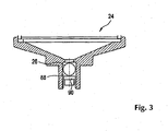
- FIG. 3 Shown in FIG. 3 is a cross-sectional view of a valve housing 24 in accordance with the present invention. As shown in FIG. 3 , a valve 88 is formed with the valve housing 24. In an exemplary embodiment of the present invention, the valve 88 is a floating ball valve where a ball 26 is positioned at valve seat 90.
- the dehydrator breather 10 of the present invention prevents desiccant particulate from interfering with airflow into and out of the dehydrating breather.
- the dehydrating breather of the present invention prevents desiccant particles from interfering with the flow of water, which may accumulate within the vessel 12, out of the dehydrator breather 10.
Landscapes
- Chemical & Material Sciences (AREA)
- Engineering & Computer Science (AREA)
- Analytical Chemistry (AREA)
- General Chemical & Material Sciences (AREA)
- Oil, Petroleum & Natural Gas (AREA)
- Chemical Kinetics & Catalysis (AREA)
- Drying Of Gases (AREA)
- Separation Of Gases By Adsorption (AREA)
- Filtering Of Dispersed Particles In Gases (AREA)
- Self-Closing Valves And Venting Or Aerating Valves (AREA)
Claims (11)
- Dispositif de reniflard déshydratant (10), comprenant:un réservoir (12), dans lequel un bac de dessiccateur (14), englobant un bouchon (66) pour assurer l'étanchéité du bac de dessiccateur (14), et le bouchon (66) comprenant un orifice (75) pour un raccordement à une cuve de transformateur (27), dans lequel le bouchon (66) est fixé au réservoir (12), via un réchauffeur (15), en utilisant des mécanismes de montage (68, 70) et des mécanismes de verrouillage (72, 74), dans lequel le bac de dessiccateur (14) est utilisé pour contenir du dessiccateur, dans lequel le bac de dessiccateur (14) est monté à l'intérieur dudit réservoir (12) et le réchauffeur (15) dans le bac de dessiccateur (14) est utilisé pour extraire l'humidité du dessiccateur; et dans lequel le réchauffeur (15) est positionné dans le bac de dessiccateur (14) et le réchauffeur (15) est fixé au bac de dessiccateur (14) en utilisant des mécanismes de montage (16, 18) et des mécanismes de verrouillage (20, 22), le dispositif (10) comprenant en outre un connecteur (73) pour contrôler le fonctionnement du réchauffeur (15); etun corps (24) de vanne associé au fond du réservoir (12), dans lequel ledit corps (24) de vanne est associé au réservoir (12) et est fixé au réservoir (12) au moyen de mécanismes de montage (16, 18) et de mécanismes de verrouillage (30, 32); etcomprenant en outre un ensemble d'évents (34), dans lequel ledit ensemble d'évents (34) est couplé au corps (24) de vanne, et comprenant:un corps d'ensemble d'évents; etau moins un orifice protégé (36-42), dans lequel ledit orifice protégé (36-42) est disposé le long d'un axe vertical du corps de l'ensemble d'évents.
- Dispositif de reniflard déshydratant (10) selon la revendication 1,
caractérisé en ce que
ledit au moins un orifice protégé (36-42) est une pluralité d'orifices protégés (36-42) alignés sur un axe vertical du corps de l'ensemble d'évents, ce qui fait que, si des particules de dessiccateur venaient à bloquer l'un des orifices protégés (36-42), un orifice protégé situé au-dessus de l'orifice protégé bloqué permettrait encore à l'air d'entrer et de sortir du corps (24) de vanne. - Dispositif de reniflard déshydratant (10) selon la revendication 1,
caractérisé en ce que
l'ensemble d'évents (34) présente des portions filetées et le corps (24) de vanne est associé par filetage à l'ensemble d'évents (34). - Dispositif de reniflard déshydratant (10) selon la revendication 1,
caractérisé en ce que
un joint d'étanchéité (28) est présent entre le réservoir (12) et le corps (24) de vanne. - Dispositif de reniflard déshydratant (10) selon la revendication 1,
caractérisé en ce que
le corps (24) de vanne comprend une bille flottante (26) qui s'ajuste dans le corps (24) de vanne et commande le flux d'air vers et hors du réservoir (12) en fonction d'une différence de pression d'air entre le réservoir (12) et la cuve (27) de transformateur. - Dispositif de reniflard déshydratant (10) selon la revendication 1,
caractérisé en ce que
il comprend en outre un filtre (52), ledit filtre (52) étant positionné dans le réservoir et empêchant des particules de dessiccateur qui s'échappent du bac de dessiccateur de pénétrer dans le corps (24) de vanne. - Dispositif de reniflard déshydratant (10) selon la revendication 6,
caractérisé en ce que
le filtre est fait d'un papier en fibres de verre. - Dispositif de reniflard déshydratant (10) selon la revendication 6,
caractérisé en ce que
il comprend en outre des supports (54, 56) qui sont utilisés pour assujettir le filtre (52) à l'intérieur du réservoir (12). - Procédé d'utilisation d'un dispositif de reniflard déshydratant (10) selon l'une quelconque des revendications 1 à 5, comprenant:la régulation d'air traversant le dispositif de reniflard déshydratant (10) en utilisant le corps de vanne (24);l'extraction de l'humidité de l'air en utilisant le dessiccateur;la conservation du dessiccateur dans le bac (14) de dessiccateur; etla capture de tout dessiccateur qui traverse le bac (14) de dessiccateur avec ledit au moins un orifice protégé (36-42) positionné sur une surface du corps de l'ensemble d'évents.
- Dispositif de reniflard déshydratant (10) selon la revendication 1,
caractérisé en ce que
ledit ensemble d'évents (34) est un silencieux. - Dispositif de reniflard déshydratant (10) selon la revendication 10,
caractérisé en ce que
ledit orifice protégé (36-42) comprend des évents en bronze fritté qui ont de fines ouvertures qui peuvent piéger les particules de dessiccateur qui s'échappent du bac de dessiccateur (14).
Applications Claiming Priority (3)
| Application Number | Priority Date | Filing Date | Title |
|---|---|---|---|
| US235795 | 2002-09-06 | ||
| US10/235,795 US6797037B2 (en) | 2002-09-06 | 2002-09-06 | Dehydrating breather apparatus and method |
| PCT/US2003/027731 WO2004022204A1 (fr) | 2002-09-06 | 2003-09-05 | Appareil et procede renifleur deshydrateur |
Publications (3)
| Publication Number | Publication Date |
|---|---|
| EP1575690A1 EP1575690A1 (fr) | 2005-09-21 |
| EP1575690A4 EP1575690A4 (fr) | 2007-02-28 |
| EP1575690B1 true EP1575690B1 (fr) | 2015-11-04 |
Family
ID=31977579
Family Applications (1)
| Application Number | Title | Priority Date | Filing Date |
|---|---|---|---|
| EP03749416.8A Expired - Lifetime EP1575690B1 (fr) | 2002-09-06 | 2003-09-05 | Appareil et procede renifleur deshydrateur |
Country Status (9)
| Country | Link |
|---|---|
| US (3) | US6797037B2 (fr) |
| EP (1) | EP1575690B1 (fr) |
| CN (1) | CN100381194C (fr) |
| AU (1) | AU2003268451A1 (fr) |
| BR (1) | BR0314467B1 (fr) |
| CA (1) | CA2497852C (fr) |
| HU (1) | HUE026678T2 (fr) |
| MX (1) | MXPA05002502A (fr) |
| WO (1) | WO2004022204A1 (fr) |
Families Citing this family (22)
| Publication number | Priority date | Publication date | Assignee | Title |
|---|---|---|---|---|
| US6846454B2 (en) * | 2001-12-24 | 2005-01-25 | Agilent Technologies, Inc. | Fluid exit in reaction chambers |
| US6797037B2 (en) * | 2002-09-06 | 2004-09-28 | Waukesha Electric Systems, Incorporated | Dehydrating breather apparatus and method |
| US7332015B2 (en) * | 2002-09-06 | 2008-02-19 | Waukesha Electric Systems, Inc | Automatic dehydrating breather apparatus and method |
| US7462222B2 (en) * | 2004-10-05 | 2008-12-09 | Caterpillar Inc. | Filter service system |
| US7419532B2 (en) * | 2004-10-05 | 2008-09-02 | Caterpillar Inc. | Deposition system and method |
| US7384455B2 (en) * | 2004-10-05 | 2008-06-10 | Caterpillar Inc. | Filter service system and method |
| US7410529B2 (en) * | 2004-10-05 | 2008-08-12 | Caterpillar Inc. | Filter service system and method |
| US7566358B2 (en) * | 2005-10-05 | 2009-07-28 | Veeder-Root Company | Fuel storage tank pressure management system and method employing a carbon canister |
| MX2009006800A (es) * | 2006-12-21 | 2009-07-02 | Procter & Gamble | Dispositivo y metodo para medir el suministro. |
| US8499788B2 (en) * | 2008-06-03 | 2013-08-06 | Richard J. RAYMO, SR. | Dry air fuel vent breather |
| CN101496982B (zh) * | 2009-01-16 | 2012-04-18 | 尹智鸿 | 抽湿设备和抽湿系统 |
| CN102350092B (zh) * | 2011-07-27 | 2013-08-14 | 许盛英 | 醇基杀菌保鲜液脱水装置 |
| USD698653S1 (en) | 2012-10-01 | 2014-02-04 | Daniel R. Schumaier | Desiccant container |
| US9114353B2 (en) | 2012-12-18 | 2015-08-25 | Waukesha Electric Systems, Inc. | Dehumidifier and breather configured for operation during regeneration |
| US8871005B2 (en) * | 2012-12-31 | 2014-10-28 | Qualitrol Company, Llc | Methods of regenerating desiccant in a breathing apparatus |
| CN104036926A (zh) * | 2014-07-01 | 2014-09-10 | 国家电网公司 | 一种具有在线再生功能的主变呼吸器及使用方法 |
| CN105674725A (zh) * | 2016-04-01 | 2016-06-15 | 安庆市德创机电产品设计有限公司 | 反冲洗过滤器电控装置干燥维护组件 |
| CN107342156A (zh) * | 2017-07-04 | 2017-11-10 | 广东电网有限责任公司惠州供电局 | 一种新型主变压器本体呼吸器装置 |
| CN107240483B (zh) * | 2017-07-31 | 2023-06-02 | 国网新疆电力公司巴州供电公司 | 变压器呼吸器 |
| US10427081B1 (en) * | 2017-08-11 | 2019-10-01 | Newman IP LLC | Drum vent filter with pressure indicator/stop assembly |
| DE112019004535A5 (de) * | 2018-09-11 | 2021-06-02 | Mann+Hummel Gmbh | Trocknungssystem, trocknerkartusche und verwendung einer trocknerkartusche |
| CN111540566A (zh) * | 2020-05-13 | 2020-08-14 | 蔡金明 | 一种防漏油变压器 |
Family Cites Families (26)
| Publication number | Priority date | Publication date | Assignee | Title |
|---|---|---|---|---|
| US2083732A (en) * | 1932-11-22 | 1937-06-15 | Pittsburgh Res Corp | Adsorbent apparatus |
| US2505581A (en) * | 1945-03-26 | 1950-04-25 | Gen Electric | Means for drying gas in electrical apparatus |
| US2669320A (en) * | 1949-08-26 | 1954-02-16 | Paul B Shaw | Water separator and filter for air pressure lines |
| GB1199941A (en) | 1967-04-19 | 1970-07-22 | Grace W R & Co | A Gas Breather Assembly |
| US3572008A (en) * | 1968-10-25 | 1971-03-23 | Hankison Corp | Methods and means for cleaning and drying compressed fluid systems |
| US3731678A (en) * | 1971-03-05 | 1973-05-08 | Phyllis Pyzel | Smoke inhalation protector |
| US3815752A (en) * | 1972-03-02 | 1974-06-11 | Sporlan Valve Co | Refrigerant filter-drier |
| US4127395A (en) | 1976-10-18 | 1978-11-28 | Pall Corporation | Adsorbent fractionator with fail-safe automatic cycle control and process |
| US4322223A (en) | 1979-03-30 | 1982-03-30 | Pall Corporation | Adsorbent fractionators with electronic sequence timer cycle control and process |
| IT1121117B (it) | 1979-06-06 | 1986-03-26 | Lattuada Sergio | Metodo per automatizzare ed ottimizzare il ciclo operativo di impianti di disidratazione ad adsorbimento |
| CA1158991A (fr) * | 1980-05-02 | 1983-12-20 | Barton A. Gravatt | Systeme de fractionnement pour adsorbant avec commande automatique du cycle |
| JPS579319U (fr) * | 1980-06-14 | 1982-01-18 | ||
| US4543446A (en) * | 1981-02-09 | 1985-09-24 | General Electric Company | Vaporization-cooled transformer havig provisions for replenishment of molecular sieve material |
| US4546442A (en) | 1982-11-24 | 1985-10-08 | Pall Corporation | Microcomputer control system for desiccant dryer |
| US4504286A (en) | 1984-04-25 | 1985-03-12 | Phillips Petroleum Company | Automatic drying tower switching system |
| JPS61174707A (ja) * | 1985-01-30 | 1986-08-06 | Toshiba Corp | ガス絶縁変圧器 |
| US4677929A (en) * | 1986-02-28 | 1987-07-07 | Harris William B | Desiccant cartridge for fuel tank vent line |
| US5427609A (en) * | 1993-09-14 | 1995-06-27 | Horton Industries, Inc. | Device for cleaning and drying compressed gas |
| US6235192B1 (en) * | 1997-03-20 | 2001-05-22 | Parker-Hannifin Corporation | Biflow drier with improved filtration |
| US5902381A (en) * | 1997-05-30 | 1999-05-11 | General Signal Corporation | Dehydrating breather apparatus |
| US6071321A (en) * | 1997-11-26 | 2000-06-06 | Westinghouse Air Brake Company | E-1 air dryer liquid separator with baffle |
| DE20104259U1 (de) | 2001-03-01 | 2001-06-07 | Siemens AG, 80333 München | Luftentfeuchter für ölisolierte Transformatoren oder Induktivitäten |
| PT1313112E (pt) * | 2001-11-13 | 2004-06-30 | Reinhausen Maschf Scheubeck | Desumificador para transformadores bobinas de reactancia bem como comutadores escalonados isolados a oleo |
| US6835235B2 (en) * | 2002-01-25 | 2004-12-28 | Sporlan Valve Company | Molded core filter drier with filter media molded to core for use in heat pump systems |
| US6797037B2 (en) * | 2002-09-06 | 2004-09-28 | Waukesha Electric Systems, Incorporated | Dehydrating breather apparatus and method |
| DE10315719B3 (de) * | 2003-04-04 | 2004-12-23 | Maschinenfabrik Reinhausen Gmbh | Luftentfeuchter für ölisolierte Transformatoren, Drosselspulen sowie Stufenschalter |
-
2002
- 2002-09-06 US US10/235,795 patent/US6797037B2/en not_active Expired - Lifetime
-
2003
- 2003-09-05 AU AU2003268451A patent/AU2003268451A1/en not_active Abandoned
- 2003-09-05 MX MXPA05002502A patent/MXPA05002502A/es active IP Right Grant
- 2003-09-05 CA CA 2497852 patent/CA2497852C/fr not_active Expired - Lifetime
- 2003-09-05 EP EP03749416.8A patent/EP1575690B1/fr not_active Expired - Lifetime
- 2003-09-05 HU HUE03749416A patent/HUE026678T2/en unknown
- 2003-09-05 BR BR0314467A patent/BR0314467B1/pt not_active IP Right Cessation
- 2003-09-05 CN CNB038211629A patent/CN100381194C/zh not_active Expired - Fee Related
- 2003-09-05 WO PCT/US2003/027731 patent/WO2004022204A1/fr not_active Ceased
-
2004
- 2004-07-23 US US10/896,989 patent/US7285150B2/en not_active Expired - Lifetime
-
2010
- 2010-02-19 US US12/708,730 patent/USRE42058E1/en not_active Expired - Lifetime
Also Published As
| Publication number | Publication date |
|---|---|
| US7285150B2 (en) | 2007-10-23 |
| CN1681575A (zh) | 2005-10-12 |
| US20040045435A1 (en) | 2004-03-11 |
| EP1575690A1 (fr) | 2005-09-21 |
| MXPA05002502A (es) | 2005-11-17 |
| BR0314467B1 (pt) | 2013-09-10 |
| BR0314467A (pt) | 2005-08-16 |
| WO2004022204A1 (fr) | 2004-03-18 |
| EP1575690A4 (fr) | 2007-02-28 |
| HUE026678T2 (en) | 2016-06-28 |
| CA2497852C (fr) | 2011-03-22 |
| US20050000356A1 (en) | 2005-01-06 |
| AU2003268451A1 (en) | 2004-03-29 |
| USRE42058E1 (en) | 2011-01-25 |
| WO2004022204A9 (fr) | 2004-04-29 |
| CN100381194C (zh) | 2008-04-16 |
| CA2497852A1 (fr) | 2004-03-18 |
| US6797037B2 (en) | 2004-09-28 |
Similar Documents
| Publication | Publication Date | Title |
|---|---|---|
| EP1575690B1 (fr) | Appareil et procede renifleur deshydrateur | |
| CA2593528C (fr) | Appareil respiratoire deshydratant automatique et methode | |
| TW202219682A (zh) | 主動蒸氣管理的兩相浸沒式冷卻裝置 | |
| US7886546B2 (en) | Wind power installation | |
| US7563310B2 (en) | Air dehumidifier for oil-insulated transformers, choke coils and steps switches | |
| US5665146A (en) | Dehumidifier | |
| KR20180064030A (ko) | 태양광 발전용 접속반 | |
| KR101928990B1 (ko) | 다기능 에어브리더 | |
| US20070107647A1 (en) | Dehumidifying radome vent | |
| JP2003229680A (ja) | 屋外設置用電子機器筐体装置 | |
| EP3181211A1 (fr) | Déshumidificateur comprenant une purge conçu pour fonctionner pendant son régénération | |
| KR102025705B1 (ko) | 절연유 건조기능과 절연파괴 억제력이 향상된 전력용 변압기 | |
| HK1112528B (en) | Automatic dehydrating breather apparatus and dehydrating system | |
| WO2022239044A1 (fr) | Dispositif de filtration pour dispositif reniflard auto-régénérant | |
| HK1091026B (en) | Air de-humidifier for oil-insulated transformers, choke coils and step switches | |
| JPH06101862A (ja) | 除湿によって生じた除湿水の排水装置 | |
| MXPA97005852A (es) | Dispositivo de recuperacion de aceite con base deevaporador y filtro montado en el cabezal |
Legal Events
| Date | Code | Title | Description |
|---|---|---|---|
| PUAI | Public reference made under article 153(3) epc to a published international application that has entered the european phase |
Free format text: ORIGINAL CODE: 0009012 |
|
| 17P | Request for examination filed |
Effective date: 20050308 |
|
| AK | Designated contracting states |
Kind code of ref document: A1 Designated state(s): AT BE BG CH CY CZ DE DK EE ES FI FR GB GR HU IE IT LI LU MC NL PT RO SE SI SK TR |
|
| AX | Request for extension of the european patent |
Extension state: AL LT LV MK |
|
| DAX | Request for extension of the european patent (deleted) | ||
| A4 | Supplementary search report drawn up and despatched |
Effective date: 20070126 |
|
| 17Q | First examination report despatched |
Effective date: 20090223 |
|
| GRAP | Despatch of communication of intention to grant a patent |
Free format text: ORIGINAL CODE: EPIDOSNIGR1 |
|
| INTG | Intention to grant announced |
Effective date: 20150629 |
|
| GRAS | Grant fee paid |
Free format text: ORIGINAL CODE: EPIDOSNIGR3 |
|
| GRAA | (expected) grant |
Free format text: ORIGINAL CODE: 0009210 |
|
| AK | Designated contracting states |
Kind code of ref document: B1 Designated state(s): AT BE BG CH CY CZ DE DK EE ES FI FR GB GR HU IE IT LI LU MC NL PT RO SE SI SK TR |
|
| REG | Reference to a national code |
Ref country code: GB Ref legal event code: FG4D |
|
| REG | Reference to a national code |
Ref country code: CH Ref legal event code: EP |
|
| REG | Reference to a national code |
Ref country code: AT Ref legal event code: REF Ref document number: 758806 Country of ref document: AT Kind code of ref document: T Effective date: 20151115 |
|
| REG | Reference to a national code |
Ref country code: IE Ref legal event code: FG4D |
|
| REG | Reference to a national code |
Ref country code: DE Ref legal event code: R096 Ref document number: 60348215 Country of ref document: DE |
|
| REG | Reference to a national code |
Ref country code: NL Ref legal event code: MP Effective date: 20151104 |
|
| REG | Reference to a national code |
Ref country code: AT Ref legal event code: MK05 Ref document number: 758806 Country of ref document: AT Kind code of ref document: T Effective date: 20151104 |
|
| PG25 | Lapsed in a contracting state [announced via postgrant information from national office to epo] |
Ref country code: IT Free format text: LAPSE BECAUSE OF FAILURE TO SUBMIT A TRANSLATION OF THE DESCRIPTION OR TO PAY THE FEE WITHIN THE PRESCRIBED TIME-LIMIT Effective date: 20151104 Ref country code: ES Free format text: LAPSE BECAUSE OF FAILURE TO SUBMIT A TRANSLATION OF THE DESCRIPTION OR TO PAY THE FEE WITHIN THE PRESCRIBED TIME-LIMIT Effective date: 20151104 Ref country code: NL Free format text: LAPSE BECAUSE OF FAILURE TO SUBMIT A TRANSLATION OF THE DESCRIPTION OR TO PAY THE FEE WITHIN THE PRESCRIBED TIME-LIMIT Effective date: 20151104 |
|
| PG25 | Lapsed in a contracting state [announced via postgrant information from national office to epo] |
Ref country code: PT Free format text: LAPSE BECAUSE OF FAILURE TO SUBMIT A TRANSLATION OF THE DESCRIPTION OR TO PAY THE FEE WITHIN THE PRESCRIBED TIME-LIMIT Effective date: 20160304 Ref country code: AT Free format text: LAPSE BECAUSE OF FAILURE TO SUBMIT A TRANSLATION OF THE DESCRIPTION OR TO PAY THE FEE WITHIN THE PRESCRIBED TIME-LIMIT Effective date: 20151104 Ref country code: FI Free format text: LAPSE BECAUSE OF FAILURE TO SUBMIT A TRANSLATION OF THE DESCRIPTION OR TO PAY THE FEE WITHIN THE PRESCRIBED TIME-LIMIT Effective date: 20151104 Ref country code: GR Free format text: LAPSE BECAUSE OF FAILURE TO SUBMIT A TRANSLATION OF THE DESCRIPTION OR TO PAY THE FEE WITHIN THE PRESCRIBED TIME-LIMIT Effective date: 20160205 Ref country code: SE Free format text: LAPSE BECAUSE OF FAILURE TO SUBMIT A TRANSLATION OF THE DESCRIPTION OR TO PAY THE FEE WITHIN THE PRESCRIBED TIME-LIMIT Effective date: 20151104 |
|
| REG | Reference to a national code |
Ref country code: HU Ref legal event code: AG4A Ref document number: E026678 Country of ref document: HU |
|
| REG | Reference to a national code |
Ref country code: DE Ref legal event code: R097 Ref document number: 60348215 Country of ref document: DE |
|
| PG25 | Lapsed in a contracting state [announced via postgrant information from national office to epo] |
Ref country code: SK Free format text: LAPSE BECAUSE OF FAILURE TO SUBMIT A TRANSLATION OF THE DESCRIPTION OR TO PAY THE FEE WITHIN THE PRESCRIBED TIME-LIMIT Effective date: 20151104 Ref country code: DK Free format text: LAPSE BECAUSE OF FAILURE TO SUBMIT A TRANSLATION OF THE DESCRIPTION OR TO PAY THE FEE WITHIN THE PRESCRIBED TIME-LIMIT Effective date: 20151104 Ref country code: EE Free format text: LAPSE BECAUSE OF FAILURE TO SUBMIT A TRANSLATION OF THE DESCRIPTION OR TO PAY THE FEE WITHIN THE PRESCRIBED TIME-LIMIT Effective date: 20151104 Ref country code: RO Free format text: LAPSE BECAUSE OF FAILURE TO SUBMIT A TRANSLATION OF THE DESCRIPTION OR TO PAY THE FEE WITHIN THE PRESCRIBED TIME-LIMIT Effective date: 20151104 |
|
| PLBE | No opposition filed within time limit |
Free format text: ORIGINAL CODE: 0009261 |
|
| STAA | Information on the status of an ep patent application or granted ep patent |
Free format text: STATUS: NO OPPOSITION FILED WITHIN TIME LIMIT |
|
| 26N | No opposition filed |
Effective date: 20160805 |
|
| PG25 | Lapsed in a contracting state [announced via postgrant information from national office to epo] |
Ref country code: SI Free format text: LAPSE BECAUSE OF FAILURE TO SUBMIT A TRANSLATION OF THE DESCRIPTION OR TO PAY THE FEE WITHIN THE PRESCRIBED TIME-LIMIT Effective date: 20151104 |
|
| PG25 | Lapsed in a contracting state [announced via postgrant information from national office to epo] |
Ref country code: BE Free format text: LAPSE BECAUSE OF FAILURE TO SUBMIT A TRANSLATION OF THE DESCRIPTION OR TO PAY THE FEE WITHIN THE PRESCRIBED TIME-LIMIT Effective date: 20151104 |
|
| PG25 | Lapsed in a contracting state [announced via postgrant information from national office to epo] |
Ref country code: MC Free format text: LAPSE BECAUSE OF FAILURE TO SUBMIT A TRANSLATION OF THE DESCRIPTION OR TO PAY THE FEE WITHIN THE PRESCRIBED TIME-LIMIT Effective date: 20151104 |
|
| REG | Reference to a national code |
Ref country code: CH Ref legal event code: PL |
|
| GBPC | Gb: european patent ceased through non-payment of renewal fee |
Effective date: 20160905 |
|
| REG | Reference to a national code |
Ref country code: IE Ref legal event code: MM4A |
|
| REG | Reference to a national code |
Ref country code: FR Ref legal event code: ST Effective date: 20170531 |
|
| PG25 | Lapsed in a contracting state [announced via postgrant information from national office to epo] |
Ref country code: IE Free format text: LAPSE BECAUSE OF NON-PAYMENT OF DUE FEES Effective date: 20160905 Ref country code: FR Free format text: LAPSE BECAUSE OF NON-PAYMENT OF DUE FEES Effective date: 20160930 Ref country code: LI Free format text: LAPSE BECAUSE OF NON-PAYMENT OF DUE FEES Effective date: 20160930 Ref country code: GB Free format text: LAPSE BECAUSE OF NON-PAYMENT OF DUE FEES Effective date: 20160905 Ref country code: CH Free format text: LAPSE BECAUSE OF NON-PAYMENT OF DUE FEES Effective date: 20160930 |
|
| PG25 | Lapsed in a contracting state [announced via postgrant information from national office to epo] |
Ref country code: LU Free format text: LAPSE BECAUSE OF NON-PAYMENT OF DUE FEES Effective date: 20160905 |
|
| PG25 | Lapsed in a contracting state [announced via postgrant information from national office to epo] |
Ref country code: CY Free format text: LAPSE BECAUSE OF FAILURE TO SUBMIT A TRANSLATION OF THE DESCRIPTION OR TO PAY THE FEE WITHIN THE PRESCRIBED TIME-LIMIT Effective date: 20151104 |
|
| PG25 | Lapsed in a contracting state [announced via postgrant information from national office to epo] |
Ref country code: TR Free format text: LAPSE BECAUSE OF FAILURE TO SUBMIT A TRANSLATION OF THE DESCRIPTION OR TO PAY THE FEE WITHIN THE PRESCRIBED TIME-LIMIT Effective date: 20151104 |
|
| PG25 | Lapsed in a contracting state [announced via postgrant information from national office to epo] |
Ref country code: BG Free format text: LAPSE BECAUSE OF FAILURE TO SUBMIT A TRANSLATION OF THE DESCRIPTION OR TO PAY THE FEE WITHIN THE PRESCRIBED TIME-LIMIT Effective date: 20151104 |
|
| PGFP | Annual fee paid to national office [announced via postgrant information from national office to epo] |
Ref country code: DE Payment date: 20180927 Year of fee payment: 16 |
|
| PGFP | Annual fee paid to national office [announced via postgrant information from national office to epo] |
Ref country code: CZ Payment date: 20180829 Year of fee payment: 16 Ref country code: HU Payment date: 20180828 Year of fee payment: 16 |
|
| REG | Reference to a national code |
Ref country code: DE Ref legal event code: R119 Ref document number: 60348215 Country of ref document: DE |
|
| PG25 | Lapsed in a contracting state [announced via postgrant information from national office to epo] |
Ref country code: CZ Free format text: LAPSE BECAUSE OF NON-PAYMENT OF DUE FEES Effective date: 20190905 |
|
| PG25 | Lapsed in a contracting state [announced via postgrant information from national office to epo] |
Ref country code: DE Free format text: LAPSE BECAUSE OF NON-PAYMENT OF DUE FEES Effective date: 20200401 |
|
| PG25 | Lapsed in a contracting state [announced via postgrant information from national office to epo] |
Ref country code: HU Free format text: LAPSE BECAUSE OF NON-PAYMENT OF DUE FEES Effective date: 20190906 |