EP1575233B1 - Système et procédé pour transmettre une sous-voie dans des systèmes de communications à accès multiple par répartition orthogonale de fréquence (OFDMA) - Google Patents
Système et procédé pour transmettre une sous-voie dans des systèmes de communications à accès multiple par répartition orthogonale de fréquence (OFDMA) Download PDFInfo
- Publication number
- EP1575233B1 EP1575233B1 EP20050005512 EP05005512A EP1575233B1 EP 1575233 B1 EP1575233 B1 EP 1575233B1 EP 20050005512 EP20050005512 EP 20050005512 EP 05005512 A EP05005512 A EP 05005512A EP 1575233 B1 EP1575233 B1 EP 1575233B1
- Authority
- EP
- European Patent Office
- Prior art keywords
- sub
- carriers
- channel
- predetermined
- sequence
- Prior art date
- Legal status (The legal status is an assumption and is not a legal conclusion. Google has not performed a legal analysis and makes no representation as to the accuracy of the status listed.)
- Active
Links
Images

Classifications
-
- H—ELECTRICITY
- H04—ELECTRIC COMMUNICATION TECHNIQUE
- H04L—TRANSMISSION OF DIGITAL INFORMATION, e.g. TELEGRAPHIC COMMUNICATION
- H04L27/00—Modulated-carrier systems
- H04L27/26—Systems using multi-frequency codes
-
- H—ELECTRICITY
- H04—ELECTRIC COMMUNICATION TECHNIQUE
- H04L—TRANSMISSION OF DIGITAL INFORMATION, e.g. TELEGRAPHIC COMMUNICATION
- H04L5/00—Arrangements affording multiple use of the transmission path
- H04L5/003—Arrangements for allocating sub-channels of the transmission path
- H04L5/0037—Inter-user or inter-terminal allocation
-
- H—ELECTRICITY
- H04—ELECTRIC COMMUNICATION TECHNIQUE
- H04L—TRANSMISSION OF DIGITAL INFORMATION, e.g. TELEGRAPHIC COMMUNICATION
- H04L1/00—Arrangements for detecting or preventing errors in the information received
- H04L1/004—Arrangements for detecting or preventing errors in the information received by using forward error control
- H04L1/0056—Systems characterized by the type of code used
- H04L1/0061—Error detection codes
-
- H—ELECTRICITY
- H04—ELECTRIC COMMUNICATION TECHNIQUE
- H04L—TRANSMISSION OF DIGITAL INFORMATION, e.g. TELEGRAPHIC COMMUNICATION
- H04L1/00—Arrangements for detecting or preventing errors in the information received
- H04L1/004—Arrangements for detecting or preventing errors in the information received by using forward error control
- H04L1/0056—Systems characterized by the type of code used
- H04L1/0071—Use of interleaving
-
- H—ELECTRICITY
- H04—ELECTRIC COMMUNICATION TECHNIQUE
- H04L—TRANSMISSION OF DIGITAL INFORMATION, e.g. TELEGRAPHIC COMMUNICATION
- H04L5/00—Arrangements affording multiple use of the transmission path
- H04L5/003—Arrangements for allocating sub-channels of the transmission path
- H04L5/0044—Arrangements for allocating sub-channels of the transmission path allocation of payload
-
- H—ELECTRICITY
- H04—ELECTRIC COMMUNICATION TECHNIQUE
- H04W—WIRELESS COMMUNICATION NETWORKS
- H04W16/00—Network planning, e.g. coverage or traffic planning tools; Network deployment, e.g. resource partitioning or cells structures
- H04W16/02—Resource partitioning among network components, e.g. reuse partitioning
- H04W16/12—Fixed resource partitioning
-
- H—ELECTRICITY
- H04—ELECTRIC COMMUNICATION TECHNIQUE
- H04W—WIRELESS COMMUNICATION NETWORKS
- H04W28/00—Network traffic management; Network resource management
- H04W28/16—Central resource management; Negotiation of resources or communication parameters, e.g. negotiating bandwidth or QoS [Quality of Service]
-
- H—ELECTRICITY
- H04—ELECTRIC COMMUNICATION TECHNIQUE
- H04L—TRANSMISSION OF DIGITAL INFORMATION, e.g. TELEGRAPHIC COMMUNICATION
- H04L5/00—Arrangements affording multiple use of the transmission path
- H04L5/0001—Arrangements for dividing the transmission path
- H04L5/0003—Two-dimensional division
- H04L5/0005—Time-frequency
- H04L5/0007—Time-frequency the frequencies being orthogonal, e.g. OFDM(A), DMT
-
- H—ELECTRICITY
- H04—ELECTRIC COMMUNICATION TECHNIQUE
- H04L—TRANSMISSION OF DIGITAL INFORMATION, e.g. TELEGRAPHIC COMMUNICATION
- H04L5/00—Arrangements affording multiple use of the transmission path
- H04L5/0001—Arrangements for dividing the transmission path
- H04L5/0014—Three-dimensional division
- H04L5/0016—Time-frequency-code
-
- H—ELECTRICITY
- H04—ELECTRIC COMMUNICATION TECHNIQUE
- H04W—WIRELESS COMMUNICATION NETWORKS
- H04W74/00—Wireless channel access, e.g. scheduled or random access
Definitions
- the present invention relates generally to a communication system using an orthogonal frequency division multiple access (OFDMA) scheme. More particularly, the present invention relates to an apparatus and a method for transmitting a sub-channel signal while minimizing interference between adjacent cells.
- OFDMA orthogonal frequency division multiple access
- 4G 4 th generation
- QoS quality of service
- many studies are being performed with the 4G communication systems in order to provide subscribers with high speed services by ensuring mobility and QoS to wireless local area network (LAN) communication systems and wireless metropolitan area network (MAN) communication systems, which can provide services at a relatively high rate.
- LAN local area network
- MAN wireless metropolitan area network
- an institute of electrical and electronics engineers (IEEE) 802.16a communication system using an orthogonal frequency division multiplexing(OFDM) scheme and an OFDMA scheme has been suggested.
- the OFDM/OFDMA schemes are applied to the wireless MAN system to transmit a physical channel signal using a plurality of sub-carriers with a high transmission rate.
- the IEEE 802.16a communication system is based on a single cell structure without taking mobility of a subscriber station (SS) into consideration. Additionally, an IEEE 802.16e communication system, which takes mobility of the SS into consideration based on the IEEE 802.16a communication system, has been suggested.
- the IEEE 802.16e communication system considers the mobility of the SS under a multi-cell environment. In order to permit the mobility of the SS under the multi-cell environment, operational relationship between the SS and a base station (BS) must be changed. Accordingly, studies have been performed with a handover of the SS in order to support the mobility of the SS under a multi-cell structure.
- the SS having the mobility is called a mobile subscriber station (MSS).
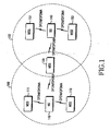
- FIG. 1 is a schematic view illustrating a conventional IEEE 802.16e communication system.
- the conventional IEEE 802.16e communication system has a multi-cell structure including a cell 100 and a cell 150.
- the conventional IEEE 802.16e communication system includes a BS 110 for managing the cell 100, a BS 140 for managing the cell 150, and a plurality of MSSs 111, 113, 130, 151, and 153.
- the BSs 110 and 140 communicate with the MSSs 111, 113, 130, 151, and 153 using the OFDM/OFDMA scheme.
- the conventional IEEE 802.16e communication system performs an inverse fast Fourier transform (IFFT).
- IFFT inverse fast Fourier transform
- the conventional IEEE 802.16e communication system uses 1702 sub-carriers.
- 166 sub-carriers are used as pilot sub-carriers and 1536 sub-carriers are used as data sub-carriers.
- the 1536 sub-carriers are divided into 32 sub-channels including 48 sub-carriers, respectively.
- the sub-channels are allocated to the MSSs according to the state of the system.
- the sub-channel signifies a channel including at least one sub-carrier.
- 48 sub-carriers may form one sub-channel.
- the sub-channel can be formed through two schemes in the conventional IEEE 802.16e communication system.
- the sub-carriers forming the sub-channels are dispersed over all frequency bands of the sub-carriers.
- sub-carriers are dispersed over the entire frequency band of the data sub-carriers, thereby obtaining a frequency diversity gain.
- the sub-carriers forming the sub-channels are aligned in the form of adjacent sub-carriers without being dispersed over all frequency bands of the sub-carriers.
- adjacent cells may use the same sub-channel in the same unit time slot.
- the same sub-channel signifies the sub-channels including the sub-carriers having the same frequency band. That is, as described with reference to FIG. 1 , two adjacent cells (cells 100 and 150) may use the same sub-channel in the same unit time slot.
- the MSS 130 which is located in a cell boundary area, can receive the signal from the BS 110, and also from the BS 140, if the signal has high strength. For example, if the signal has a high carrier to interference and noise ratio (CINR), the MSS 130 receives the signal and demodulates the signal into information data.
- MCS modulation and coding scheme
- the sub-channels of the cells forming the conventional IEEE 802.16e communication system have the same frequency band. If the same MCS is applied to the sub-channels of the cells, the MSS located in the cell boundary area can receive the sub-channel signals not only from the BS of the MSS, but also from other BS. As a result, the MSS may receive the sub-channel signal having the higher interference component. Accordingly, it is necessary to provide an apparatus and a method for transceiving the sub-channel signal, while minimizing interference between adjacent cells.
- OFDM Mode for the IEEE 802.16A PHY Draft Standard IEEE 802.16.3C-01/59R2, May 17, 2001, pages 1 to 59 , relates to OFDM mode for the IEEE 802.16A PHY draft standard.
- the symbol structure is made up of sub-channels.
- There are several methods of splitting the whole upstream OFDMA into sub-channels the first two methods are performed by first dividing the used carriers into basic groups (not including the DC carrier, which is not used) each containing a certain amount of carriers.
- the present invention has been designed to solve the above and other problems occurring in the prior art. It is the object of the present invention to provide an improved apparatus and method for transmitting a sub-channel signal in an OFDMA communication system.
- Another aspect of the present invention is to provide an apparatus and a method for interleaving a sub-channel signal in such a manner that sub-channels having adjacent sub-carriers can be differentiated from each other according to BSs thereof in an OFDMA communication system.
- BSs base stations
- the method comprises the steps of creating a basic orthogonal sequence having a length identical to a number of the sub-carriers forming the sub-channel; creating a plurality of sequences having lengths identical to the length of the basic orthogonal sequence by one of cyclic-shifting the basic orthogonal sequence a predetermined number of times and through performing a modulo operation based on a number of the sub-carriers forming the sub-channel, after adding a predetermined offset to the basic orthogonal sequence, which has been cyclic-shifted the predetermined number of times; selecting a predetermined number of sequences corresponding to a number of the BSs from among the plurality of sequences; and allocating the selected sequences as the sub-channel signal interleaving patterns for the BSs.
- BSs base stations
- a method of allocating sub-channel signal interleaving patterns to base stations (BSs) forming a wireless communication system capable of dividing a frequency band into a plurality of sub-carriers and including a plurality of sub-channels, which are a set of predetermined adjacent sub-carriers.
- the method comprises the steps of creating a basic orthogonal sequence having a length identical to a number of the sub-carriers forming the sub-channel; creating a plurality of sequences having lengths identical to the length of the basic orthogonal sequence by applying a predetermined offset to the basic orthogonal sequence, after cyclic-shifting the basic orthogonal sequence a predetermined number of times; selecting a predetermined number of sequences corresponding to a number of the BSs from among the plurality of sequences; and allocating the selected sequences as the sub-channel signal interleaving patterns for the BSs.
- a method of transmitting a sub-channel signal in a wireless communication system capable of dividing a frequency band into a plurality of sub-carriers and including a plurality of sub-channels, which are a set of predetermined adjacent sub-carriers.
- the method comprises the steps of creating coded bits by encoding information data to be transmitted through a predetermined coding scheme; creating a modulation symbol array by modulating the coded bits according to a predetermined modulation scheme; interleaving the modulation symbol array according to a predetermined sub-channel signal interleaving pattern; allocating the interleaved modulation symbol array to predetermined sub-channels; and transmitting the sub-channel signal, after performing an inverse fast Fourier transform (IFFT) process and an RF processing process with respect to the sub-channel signal.
- IFFT inverse fast Fourier transform
- an apparatus for transmitting a sub-channel signal in a wireless communication system capable of dividing a frequency band into a plurality of sub-carriers and including a plurality of sub-channels, which are a set of predetermined adjacent sub-carriers.
- the apparatus comprises an encoder for creating coded bits by encoding information data to be transmitted through a predetermined coding scheme; a symbol mapper for creating a modulation symbol array by modulating the coded bits according to a predetermined modulation scheme; a sub-channel allocator for interleaving the modulation symbol array according to a predetermined sub-channel signal interleaving pattern and for allocating the interleaved modulation symbol array to predetermined sub-channels; and a transmitter for transmitting the sub-channel signal, after performing an inverse fast Fourier transform (IFFT) process and an RF processing process with respect to the sub-channel signal.
- IFFT inverse fast Fourier transform
- the method comprises the steps of: creating a plurality of sub-channel signal interleaving patterns, which are different from each other and have a length identical to a number of sub-carriers forming the sub-channels; and allocating the interleaving patterns to the BSs such that the sub-channel signal is interleaved.
- a method of allocating sub-channel signal interleaving patterns to base stations (BSs) in a wireless communication system capable of dividing a frequency band into a plurality of sub-carriers and including a plurality of sub-channels, which are a set of predetermined adjacent sub-carriers.
- the method comprises the steps of: creating a plurality of sequences having length identical to the length of a basic sequence which has a length identical to a number of data sub-carriers forming a sub-channel by applying a predetermined offset to the basic sequence and cyclic-shifting the basic sequence a predetermined number of times; allocating the created a plurality of sequences as the sub-channel signal interleaving patterns for the BSs.
- the present invention is directed to an orthogonal frequency division multiple access(OFDMA) communication system. More specifically, the present invention suggests an interleaving scheme for a sub-channel signal capable of minimizing interference between adjacent cells in an institute of electrical and electronics engineers (IEEE) 802.16e communication system. That is, the present invention suggests an interleaving scheme for a sub-channel signal capable of minimizing interference between adjacent cells when the IEEE 802.16e communication system has a frequency reuse factor of 1, i.e., when cells forming the IEEE 802.16e communication system use the same frequency band.
- IEEE institute of electrical and electronics engineers
- the interleaving scheme for the sub-channel according to the present invention is applicable for other systems using the OFDMA scheme.
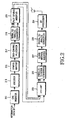
- FIG. 2 is a schematic view illustrating a transmitter for an IEEE 802.16e communication system according to an embodiment of the present invention.
- the transmitter includes a cyclic redundancy check (CRC) inserter 211, an encoder 213, a symbol mapper 215, a sub-channel allocator 217, a serial to parallel converter 219, a pilot symbol inserter 221, an inverse fast Fourier transform (IFFT) unit 223, a parallel to serial converter 225, a guard interval inserter 227, a digital to analog converter 229, and a radio frequency (RF) processor 231.
- CRC cyclic redundancy check
- IFFT inverse fast Fourier transform
- RF radio frequency
- the user data bits and control data bits are input into the CRC inserter 211.
- the user data bits and control data bits are called "information data bits”.
- the CRC inserter 211 inserts a CRC bit into the information data bits and outputs the information data bits to the encoder 213.
- the encoder 213 Upon receiving the signal from the CRC inserter 211, the encoder 213 codes the signal through a predetermined coding scheme and outputs the coded signal to the symbol mapper 215.
- the predetermined coding scheme includes a turbo coding scheme having a predetermined coding rate or a convolutional coding scheme.
- the symbol mapper 215 modulates the coded bits output from the encoder 213 through a predetermined modulation scheme, thereby forming a modulation symbol.
- the modulation symbol is output to the sub-channel allocator 217.
- the predetermined modulation scheme includes a quadrature phase shift keying (QPSK) scheme or a 16 quadrature amplitude modulation (QAM) scheme.
- the sub-channel allocator 217 receives the modulation symbols from the symbol mapper 215, allocates the modulation symbols to the sub-channels, and outputs the modulation symbols to the serial to parallel converter 219.
- the sub-channel allocator 217 allocates the sub-channels to the modulation symbols through a predetermined scheme. That is, because the IEEE 802.16e communication system has a frequency reuse factor of 1, the sub-channel allocator 217 allocates the sub-channels to the modulation symbols, after interleaving the sub-channel signal, such that interference between adjacent cells can be minimized. This allocation scheme will be described later in detail.
- the serial to parallel converter 219 Upon receiving the serial modulation symbols having the sub-channels from the sub-channel allocator 217, the serial to parallel converter 219 parallel-converts the modulation symbols and outputs the modulation symbols to the pilot symbol inserter 221.
- the pilot symbol inserter 221 inserts pilot symbols into the parallel modulation symbols and outputs the parallel modulation symbols to the IFFT unit 223.
- the IFFT unit 223 receiving the signal output from the pilot symbol inserter 221 performs an N-point IFFT with respect to the signal and sends the signal to the parallel to serial converter 225.
- the parallel to serial converter 225 Upon receiving the parallel signal from the IFFT unit 223, the parallel to serial converter 225 converts parallel signal into the serial signal and outputs the serial signal to the guard interval inserter 227. After receiving the serial signal output from the parallel to serial converter 225, the guard interval inserter 227 inserts a guard interval signal into the serial signal and outputs the serial signal to the digital to analog converter 229.
- the guard interval is used for removing interference between orthogonal frequency division multiplexing (OFDM) symbols, which have been transmitted in previous OFDM symbol time, and OFDM symbols to be transmitted in present OFDM symbol time when an OFDMA communication system transmits the OFDM symbols.
- OFDM orthogonal frequency division multiplexing
- the guard interval can be inserted into the OFDM symbol through a cyclic prefix scheme, in which predetermined final samples of the OFDM symbols in a time domain are copied and the copied samples are inserted into effective OFDM symbols, or through a cyclic postfix scheme, in which predetermined fore samples of the OFDM symbols in the time domain are copied and the copied samples are inserted into effective OFDM symbols.
- the digital to analog converter 229 After receiving the signal from the guard interval inserter 227, the digital to analog converter 229 converts the signal into an analog signal and outputs the analog signal to the RF processor 231.
- the RF processor 231 includes a filter and a front end unit, and transmits the analog signal through a transmission antenna, after RF-processing the analog signal.
- FIG. 3 is a schematic view illustrating an interleaving procedure for the sub-channel signal in the IEEE 802.16e communication system according to an embodiment of the present invention.
- the frequency reuse factor of 1 is applied to the IEEE 802.16e communication system.
- each of the sub-channels allocated from cells, that is, allocated from base stations(BSs) of the IEEE 802.16e communication system consists of a plurality of adjacent sub-carriers.
- the sub-channel can be formed by dispersing 48 sub-carriers over the frequency bands of the IEEE 802.16e communication system, or by aligning the sub-carriers in the form of adjacent sub-carriers, such that 48 adjacent sub-carriers may form one sub-channel.
- the sub-channel is formed using the adjacent sub-carriers.
- the adjacent cells select the sub-channels having the same frequency band. If the same MCS is applied to the selected sub-channels, the sub-channel signals transmitted from one cell may act as interference signals with respect to other cell. Therefore, a problem may occur when restoring the signals that have been transmitted from each BS. That is, even if BSs transmit the signals with sufficient redundancy by taking interference of adjacent BSs into consideration, a subscriber station (SS) communicating with a corresponding BS may restore a signal having higher strength between a signal transmitted from the corresponding BS and an interference signal.
- SS subscriber station
- the sufficient redundancy signifies a predetermined condition for restoring an original transmission signal when noise identical to the interference is received together with the signal instead of the interference signal to which the same MCS is applied.
- the reason for decoding the signal having higher strength between the receiving signal and the interference signal can be found from the characteristics of the decoder of the SS.
- the decoder of each SS is a system capable of selecting a codeword similar to a receiving signal from among all codewords available in a predetermined coding system. Accordingly, if the same MCS is applied to the same sub-channels, the decoder of each SS cannot detect the codeword transmitted from the BS making communication with the SS. As a result, the decoder only detects the codeword included in the receiving signal having highest strength. Accordingly, the SS cannot communicate with the corresponding BS.
- the decoder is designed such that it regards only codewords transmitted from the corresponding BS as codewords generated from the coding system. Therefore, according to the present invention, the sub-channel has a function capable of distinguishing the BSs thereof. That is, although the sub-channel of each BS includes the same sub-carriers, it is possible to vary a mapping order of the symbol to the sub-carriers to enable the sub-channel to have the BS distinguishing function.
- the sub-channel signal is transmitted while mapping the sub-channel signal with the sub-channel, after interleaving the sub-channel signal to be transmitted, thereby preventing the sub-channel signal from operating as the interference signal to the adjacent cells.
- FIG. 3 illustrates the interleaving scheme for the sub-channel signal used for a predetermined BS A and the interleaving scheme for the sub-channel signal used for the other BS B, which is adjacent to the BS A.
- the BSs A and B utilize N sub-carriers in which M adjacent sub-carriers form one sub-channel in a time-frequency domain.
- the N sub-carriers refer to a set of sub-carriers for K OFDM symbols, where K is a predetermined positive integer.
- positions of the sub-carriers forming the n th sub-channel in the BSs A and B may be identical to each other.
- the sub-carriers forming the n th sub-channel in the BSs A and B have the same frequency band, the sub-channel signal is interleaved. Accordingly, the mapping order of the sub-carrier for data symbols forming the n th sub-channel signal of the BSs A and B, that is, the mapping order of the sub-carrier for modulation symbols, can be formed differently, depending on the modulation symbols.
- one sub-channel includes 48 data sub-carriers.
- Each sub-channel of the BSs A and B includes 48 data sub-carriers, including first to forty eighth data sub-carriers, in which the 48 sub-carriers have the same frequency band.
- the signal mapped with each sub-carrier is the modulation symbol
- the sub-channel signal including 48 modulation symbols is transmitted through one sub-channel.
- the interleaving pattern of the sub-channel signal for the BS A is set differently from the interleaving pattern of the sub-channel signal for the BS B, thereby preventing the sub-channel signal transmitted from the adjacent BS from operating as the interference signal.
- the interleaving pattern for the sub-channel signal is referred to as a "sub-channel signal interleaving pattern".
- the sub-channel signal interleaving pattern of the BS A 48 modulation symbols are sequentially mapped with the sub-carriers of ⁇ 2, 14, 1, ...., 13, 3, 9 ⁇ .
- 48 modulation symbols are sequentially mapped with the sub-carriers of ⁇ 7, 13, 5, ...., 1, 8, 23 ⁇ .
- the sub-channel signal interleaving patterns must be set differently from each other depending on the BSs forming the IEEE 802.16e communication system. Accordingly, the following matters must be considered when setting the sub-channel signal interleaving patterns.
- the mapping order of the sub-carrier for the modulation symbols transmitted through the sub-channel is set using a sequence having a length M including elements ⁇ 0, 1, ...., M-1 ⁇ . Each of the elements ⁇ 0, 1, Vietnamese, M-1 ⁇ is used once in the sequence having,the length M.
- the sub-channel signal interleaving pattern can be determined through various schemes as described below by using the sequence having the length M.
- the sub-channel signal interleaving pattern can be determined by using an orthogonal sequence having a length M.
- one sub-channel includes M data sub-carriers, such that it is possible to create orthogonal sequences having the length M.
- the orthogonal sequence signifies a sequence, in which the same elements does not exist in the same location when selecting two sequences from among orthogonal sequences having the length M.
- orthogonal sequence having the length M can be created through various schemes as described below.
- orthogonal sequences having the length M which are orthogonal to each other, can be created by enabling the sequence of ⁇ 0, 1, ..., M-1 ⁇ to undergo a cyclic shift by [0, M-1] times.
- orthogonal sequences having the length M can be created through a computer simulation.
- Each of the orthogonal sequences having the length M created through the above first and second schemes is allocated as an interleaving pattern for each sub-channel signal of each BS, thereby preventing the signal of each BS from operating as the interference signal of the adjacent BS.
- the sub-channel signal interleaving pattern can be determined by using a non-orthogonal sequence having a length M.
- the number C of the BSs forming the IEEE 802.16e communication system is larger than the length M of the sequence, the number of the orthogonal sequences is less than the number C of the BSs, thereby making it impossible to distinguish all BSs by using the orthogonal sequence. Accordingly, a larger amount of non-orthogonal sequence is created by attenuating orthogonality of the orthogonal sequence, thereby distinguishing the BSs from each other. That is, there are provided M! sequences having the length M including elements ⁇ 0, 1, ...., M-1 ⁇ , in which each of the elements ⁇ 0, 1, ...., M-1 ⁇ is used once in the sequence.
- the non-orthogonal sequences having the length M can be created through the computer simulation.
- Each of the non-orthogonal sequences having the length M is allocated through the interleaving pattern of the sub-channel signal of each BS, thereby preventing the signal of each BS from operating as the interference signal of the adjacent BS.
- a predetermined orthogonal sequence So is defined as a basic orthogonal sequence. It is possible to create M 2 sequences using the basic orthogonal sequence S 0 .
- a method for creating the M 2 sequences will be described.
- sequence S f g has a predetermined remainder after cyclic-shilling the basic orthogonal sequence S 0 f times and' dividing each element of the basic orthogonal sequence So by M, while adding an offset g to the element, in which f and g have an integer value existing within a range of [0,M-1]. That is, sequence S f g can be obtained through a modulo operation by using M. Accordingly, it is possible to create total M 2 sequences S f g .
- the sequences, which undergo the cyclic shift by f times with the same offset g, have orthogonality to each other.
- the sequences having parameters g and f of different values may enable collision between elements of the sequences.
- the interleaving pattern of the sub-channel signal for each BS can be determined using the M 2 orthogonal sequences.
- the maximum number C of BSs forming the IEEE 802.16e communication system is limited to several hundreds. Therefore, it is possible to allocate the sub-channel signal interleaving pattern if the M has an integer value more than 20.
- the sequences including a relatively smaller number of sub-carriers having the collision characteristics can be selected for allocating the interleaving pattern of the sub-channel signal for the C BSs.
- the sub-channel signal interleaving pattern can be determined according to the schemes for selecting the basic orthogonal sequence So.
- the schemes for selecting the basic orthogonal sequence So will be described.
- the basic orthogonal sequence So is selected in such a manner that the number of sub-carriers having the collision characteristics can be minimized in each of the M 2 sequences. That is, C sequences are selected corresponding to the number C of BSs in which the C sequences include a predetermined number of sub-carriers, which may present collision characteristics when selecting two sequences from among the M 2 sequences, less than H sub-carriers.
- the selected C sequences are formed as a sequence sub-set. As described above, the C sequences that form the sequence sub-set can be selected through the computer simulation.
- the sub-channel signal interleaving pattern can be determined using a Reed Solomon sequence defined in a Galois Field (GF, Q p ). If the sub-channel signal interleaving pattern is determined using the Reed Solomon sequence, the Reed Solomon sequence may include a maximum of three sub-carriers having the collision characteristics.
- j th element of the Reed Solomon sequence is represented as P f g j which satisfies Equation (1).
- Equation (1) P 0 represents a basic orthogonal sequence in the GF (Q p ), and P f (j) represents a j th element of a cyclic shift orthogonal sequence, which is created through cyclic-shifting P 0 in the left direction by f.
- P f g j is a j th element of a sequence representing the sub-channel signal interleaving pattern.
- the addition operation in Equation (1) represents the addition operation in the GF (Q p ).
- the total M(M+1) sequences used for distinguishing the BSs are determined depending on the determination schemes for parameters f and g.
- the parameters f and g are determined through one of following three schemes.
- the parameter f has a predetermined integer value selected from a predetermined integer range between 0 and M-1.
- the parameter g has a predetermined integer value selected from a predetermined integer range between 0 and M.
- the sub-channel signal interleaving pattern is allocated to the BSs through the following manner.
- the sub-channel signal interleaving pattern is adapted for M orthogonal sequences and C to M sequences including a predetermined number of sub-carriers having collision characteristics less than H sub-carriers.
- predetermined serial numbers 0 to C-1 are allocated to the C sequences. That is, the sequences having a predetermined remainder after dividing indexes of C BSs by C (C-modulo operation) are allocated to the C BSs.
- an index of a BS is an index assigned uniquely to the BS in the OFDMA communication system, so the OFDMA communication system assignes indexes to a plurality of BSs of the OFDMA communication system.
- the number of sequences orthogonal to each other is set smaller than the number of sequence representing the collision characteristics, thereby allocating the sequences having the predetermined remainder, after dividing the indexes of the BSs by C (C-modulo operation) to each BS.
- a system is designed in such a manner that the BSs having the same remainder, after dividing the indexes of the BSs by C (C-modulo operation), are spaced from each other.
- the parameters f and g are determined using Equation (2).
- ⁇ x ⁇ represents a maximum integer value which is not larger than x
- c_id represents a index of the BS
- mod represents a modulo operation.
- the parameters f and g are determined by Equation (3).
- f ⁇ c_id OFFSET ⁇ ⁇ mod PERM
- g c_id mod OFFSET
- Equation (3) parameters PERM and OFFSET have the values identical to those defined in Equation (2).
- the sub-channel signal interleaving pattern for each BS is determined by using M(M+1) orthogonal sequences which satisfy Equation 1.
- the orthogonal sequences including a relatively smaller number of sub-carriers having the collision characteristics are selected to allocate the sub-channel signal interleaving pattern for each of C BSs.
- the basic orthogonal sequence P 0 can be represented as shown below through septenary notation in Equation (4).
- P 0 ⁇ 01 , 22 , 46 , 52 , 42 , 41 , 26 , 50 , 05 , 33 , 62 , 43 , 63 , 65 , 32 , 40 , 04 , 11 , 23 , 61 , 21 , 24 , 13 , 60 , 06 , 55 , 31 , 25 , 35 , 36 , 51 , 20 , 02 , 44 , 15 , 34 , 14 , 12 , 45 , 30 , 03 , 66 , 54 , 16 , 56 , 53 , 64 , 10 ⁇
- the 48 x 49 sequences are allocated to each BS according to the above three schemes.
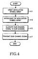
- FIG. 4 is a schematic view illustrating a procedure for transmitting the sub-channel signal in the IEEE 802.16e communication system according to an embodiment of the present invention.
- the transmitter when information data to be transmitted is generated, as described with reference to FIG. 2 , the transmitter creates a modulation symbol array by performing the CRC bit insertion, encoding, and symbol mapping processes with respect to the information data in step 411.
- the transmitter interleaves the modulation symbol array according to the sub-channel signal interleaving pattern, which has been preset in the transmitter, in step 413. Because the schemes for determining the sub-channel signal interleaving pattern have already been described above, they will not again be described below.
- step 415 the transmitter allocates the interleaved sub-channel signal to the corresponding sub-channel, that is, to the sub-carriers forming the corresponding sub-channel.
- step 417 the transmitter transmits the sub-channel signal, thereby completing the procedure for transmitting the sub-channel signal.
- the sub-channel signal transmission procedure includes the steps of converting the serial signal allocated to the sub-channel to the parallel signal, inserting the pilot symbol into the parallel signal, performing the IFFT with respect to the parallel signal, converting the parallel signal into the serial signal, inserting the guard interval into the serial signal, converting the serial signal into the analog signal, and RF-processing the analog signal.
- the present invention has been described in relation to the schemes for determining the sub-channel signal interleaving pattern, the present invention is also applicable for changing the mapping position of the sub-carriers because the process for interleaving of the sub-channel signal according to the interleaving pattern is substantially identical to the process for changing the position of the sub-carriers forming the sub-channel. That is, according to the present invention, the sub-channel signal interleaving pattern can be replaced with the mapping pattern of the sub-carriers forming the sub-channel.
- the sub-channel signals allocated with the same frequency band to adjacent cells in the OFDMA communication system are transmitted by interleaving the sub-channel signals according to the sub-channel signal interleaving pattern, such that interference caused by the sub-channel signal of the adjacent cell can be minimized, thereby improving system performance.
Claims (7)
- Procédé d'attribution de schémas d'entrelacement de signal de sous-canal à des stations de base BS, soit Base Station, formant un système de communication sans fil capable de diviser une bande de fréquence en une pluralité de sous-porteuses et comprenant une pluralité de sous-canaux, qui sont un ensemble de sous-porteuses adjacentes prédéterminées, le procédé comprenant les étapes suivantes :création d'une séquence orthogonale de base ayant une longueur identique à un nombre de sous-porteuses formant un sous-canal ;création d'une pluralité de séquences ayant des longueurs identiques à la longueur de la séquence orthogonale de base en appliquant à la séquence orthogonale de base une compensation prédéterminée et un nombre prédéterminé de décalages cycliques ;sélection d'un nombre prédéterminé de séquences correspondant à un nombre de BS parmi la pluralité de séquences ; etattribution des séquences sélectionnées.
- Procédé selon la revendication 1, dans lequel l'étape d'application de la compensation prédéterminée et du décalage cyclique est déterminée conformément à :

où
- Procédé selon la revendication 2, dans lequel, quand M égale 48, la séquence orthogonale de base est conformée comme un corps de Galois et représente {01, 22, 46, 52, 42, 41, 26, 50, 05, 33, 62, 43, 63, 65, 32, 40, 04, 11, 23, 61, 21, 24, 13, 60, 06, 55, 31, 25, 35, 36, 51, 20, 02, 44, 15, 34, 14, 12, 45, 30, 03, 66, 54, 16, 56, 53, 64, 10}.
- Procédé selon la revendication 1, dans lequel l'étape d'application de la compensation prédéterminée et du décalage cyclique est déterminée conformément à :

où


où PERM représente M, qui est le nombre de sous-porteuses formant un sous-canal, OFFSET représente M+1, └x┘ représente une valeur entière maximale inférieure ou égale à x, et c_id représente un indice de la BS. - Procédé selon la revendication 4, dans lequel, quand M égale 48, la séquence orthogonale de base est conformée comme un corps de Galois et représente {01, 22, 46, 52, 42, 41, 26, 50, 05, 33, 62, 43, 63, 65, 32, 40, 04, 11, 23, 61, 21, 24, 13, 60, 06, 55, 31, 25, 35, 36, 51, 20, 02, 44, 15, 34, 14, 12, 45, 30, 03, 66, 54, 16, 56, 53, 64, 10}.
- Procédé selon la revendication 1, dans lequel l'étape d'application de la compensation prédéterminée et du décalage cyclique est déterminée conformément à :

où


où PERM représente M, qui est le nombre des sous-porteuses formant un sous-canal, OFFSET représente M+1, └x┘ représente une valeur entière maximale inférieure ou égale à x, et c_id représente un indice de la BS. - Procédé selon la revendication 6, dans lequel, quand M égale 48, la séquence de base est conformée comme un corps de Galois et représente {01, 22, 46, 52, 42, 41, 26, 50, 05, 33, 62, 43, 63, 65, 32, 40, 04, 11, 23, 61, 21, 24, 13, 60, 06, 55, 31, 25, 35, 36, 51, 20, 02, 44, 15, 34, 14, 12, 45, 30, 03, 66, 54, 16, 56, 53, 64, 10}.
Priority Applications (1)
| Application Number | Priority Date | Filing Date | Title |
|---|---|---|---|
| EP10002184.9A EP2202930B1 (fr) | 2004-03-12 | 2005-03-14 | Système et procédé pour transmettre une sous-canal dans des systèmes de communications à accès multiple par répartition orthogonale de fréquence (OFDMA) |
Applications Claiming Priority (4)
| Application Number | Priority Date | Filing Date | Title |
|---|---|---|---|
| KR20040017065 | 2004-03-12 | ||
| KR2004017065 | 2004-03-12 | ||
| KR1020040025145A KR100713528B1 (ko) | 2004-03-12 | 2004-04-12 | 직교 주파수 분할 다중 접속 방식을 사용하는 통신시스템에서 서브 채널 신호 송신 장치 및 방법 |
| KR2004025145 | 2004-04-12 |
Related Child Applications (2)
| Application Number | Title | Priority Date | Filing Date |
|---|---|---|---|
| EP10002184.9A Division-Into EP2202930B1 (fr) | 2004-03-12 | 2005-03-14 | Système et procédé pour transmettre une sous-canal dans des systèmes de communications à accès multiple par répartition orthogonale de fréquence (OFDMA) |
| EP10002184.9A Division EP2202930B1 (fr) | 2004-03-12 | 2005-03-14 | Système et procédé pour transmettre une sous-canal dans des systèmes de communications à accès multiple par répartition orthogonale de fréquence (OFDMA) |
Publications (3)
| Publication Number | Publication Date |
|---|---|
| EP1575233A2 EP1575233A2 (fr) | 2005-09-14 |
| EP1575233A3 EP1575233A3 (fr) | 2008-09-17 |
| EP1575233B1 true EP1575233B1 (fr) | 2015-05-20 |
Family
ID=37273275
Family Applications (2)
| Application Number | Title | Priority Date | Filing Date |
|---|---|---|---|
| EP20050005512 Active EP1575233B1 (fr) | 2004-03-12 | 2005-03-14 | Système et procédé pour transmettre une sous-voie dans des systèmes de communications à accès multiple par répartition orthogonale de fréquence (OFDMA) |
| EP10002184.9A Active EP2202930B1 (fr) | 2004-03-12 | 2005-03-14 | Système et procédé pour transmettre une sous-canal dans des systèmes de communications à accès multiple par répartition orthogonale de fréquence (OFDMA) |
Family Applications After (1)
| Application Number | Title | Priority Date | Filing Date |
|---|---|---|---|
| EP10002184.9A Active EP2202930B1 (fr) | 2004-03-12 | 2005-03-14 | Système et procédé pour transmettre une sous-canal dans des systèmes de communications à accès multiple par répartition orthogonale de fréquence (OFDMA) |
Country Status (10)
| Country | Link |
|---|---|
| US (3) | US7715483B2 (fr) |
| EP (2) | EP1575233B1 (fr) |
| JP (1) | JP4629054B2 (fr) |
| KR (1) | KR100713528B1 (fr) |
| CN (2) | CN1930844B (fr) |
| AU (1) | AU2005222292B2 (fr) |
| BR (1) | BRPI0508675B1 (fr) |
| CA (1) | CA2557044C (fr) |
| RU (1) | RU2349050C2 (fr) |
| WO (1) | WO2005088924A1 (fr) |
Families Citing this family (41)
| Publication number | Priority date | Publication date | Assignee | Title |
|---|---|---|---|---|
| US8040986B2 (en) * | 2003-11-26 | 2011-10-18 | Texas Instruments Incorporated | Frequency-domain subchannel transmit antenna selection and power pouring for multi-antenna transmission |
| KR100617835B1 (ko) * | 2005-01-05 | 2006-08-28 | 삼성전자주식회사 | 통신 시스템에서 채널 품질 정보 송수신 장치 및 방법 |
| KR100965699B1 (ko) * | 2005-03-25 | 2010-06-24 | 삼성전자주식회사 | 이동 통신 시스템에서 부채널 신호 송수신 장치 및 송신 방법과 주파수 자원 할당 방법 |
| US7610017B2 (en) * | 2005-06-09 | 2009-10-27 | Vixs Systems, Inc. | Increased data rate transmissions of a wireless communication |
| WO2007013560A1 (fr) * | 2005-07-29 | 2007-02-01 | Matsushita Electric Industrial Co., Ltd. | Dispositif de station de base de communication sans fil, dispositif de station mobile de communication sans fil et procédé d'attribution de séquence de signal pilote dans une communication à porteuses multiples |
| US7983350B1 (en) | 2005-10-25 | 2011-07-19 | Altera Corporation | Downlink subchannelization module |
| KR100895183B1 (ko) | 2006-02-03 | 2009-04-24 | 삼성전자주식회사 | 무선통신 시스템을 위한 주변 셀 간섭의 제거를 위한송수신 방법 및 장치 |
| US8538443B2 (en) | 2006-03-20 | 2013-09-17 | Research In Motion Limited | Method and system for adjusting communication mode by adjusting the power level for a fractional frequency reuse in a wireless communication network |
| KR101035083B1 (ko) * | 2006-04-26 | 2011-05-19 | 재단법인서울대학교산학협력재단 | 다중 셀 통신 시스템에서 자원 이용 방법 및 시스템 |
| CN101047393B (zh) * | 2006-05-12 | 2010-05-12 | 华为技术有限公司 | 一种产生交织器/解交织器的方法及其应用 |
| JP4793569B2 (ja) * | 2006-06-19 | 2011-10-12 | 日本電気株式会社 | 帯域割当方法および無線通信システム |
| GB2458418B (en) | 2006-12-19 | 2011-08-03 | Lg Electronics Inc | Sequence generating method for efficient detection and method for transmitting and receiving signals using the same |
| JP2008160720A (ja) * | 2006-12-26 | 2008-07-10 | Fujitsu Ltd | 複数のセクタ対応の送信部を備えた無線基地局及び複数のセクタ用の信号の送信方法 |
| US20080225688A1 (en) * | 2007-03-14 | 2008-09-18 | Kowalski John M | Systems and methods for improving reference signals for spatially multiplexed cellular systems |
| US8611440B2 (en) | 2007-10-30 | 2013-12-17 | Huawei Technologies Co., Ltd. | Systems and methods for generating sequences that are nearest to a set of sequences with minimum average cross-correlation |
| US8112041B2 (en) | 2007-03-14 | 2012-02-07 | Sharp Kabushiki Kaisha | Systems and methods for generating sequences that are nearest to a set of sequences with minimum average cross-correlation |
| JP5113242B2 (ja) | 2007-05-17 | 2013-01-09 | エルジー エレクトロニクス インコーポレイティド | 無線通信システムにおいて同期信号を伝送する方法 |
| US20080310383A1 (en) * | 2007-06-15 | 2008-12-18 | Sharp Laboratories Of America, Inc. | Systems and methods for designing a sequence for code modulation of data and channel estimation |
| KR100938756B1 (ko) | 2007-07-06 | 2010-01-26 | 엘지전자 주식회사 | 무선통신 시스템에서 셀 탐색 과정을 수행하는 방법 |
| US8340014B2 (en) * | 2007-12-26 | 2012-12-25 | Lg Electronics Inc. | Method for transmitting and receiving signals using multi-band radio frequencies |
| JP5156485B2 (ja) * | 2008-05-28 | 2013-03-06 | 株式会社エヌ・ティ・ティ・ドコモ | 無線通信システム |
| EP2131540B1 (fr) * | 2008-06-04 | 2013-09-18 | Sony Corporation | Nouvelle structure de cadre pour systèmes à multiporteuses |
| US8194529B2 (en) | 2008-09-08 | 2012-06-05 | Sony Corporation | Frame and data pattern structure for multi-carrier systems |
| WO2010035969A2 (fr) | 2008-09-23 | 2010-04-01 | Lg Electronics Inc. | Appareil et procédé de transmission et de réception de données dans un transfert intercellulaire sans coupure d’un système de communication sans fil |
| AU2009217407C1 (en) | 2008-10-09 | 2015-07-23 | Sony Corporation | New frame and data pattern structure for multi-carrier systems |
| US8340211B2 (en) * | 2009-06-23 | 2012-12-25 | Samsung Electronics Co., Ltd. | Methods and apparatus to encode bandwidth request message |
| KR20120069174A (ko) * | 2010-12-20 | 2012-06-28 | 삼성전자주식회사 | 무선통신시스템에서 임의 접근 신호 수신 장치 및 방법 |
| US8705234B2 (en) * | 2011-02-23 | 2014-04-22 | Cole Patrick Schneider | Answer bracelet |
| US9569771B2 (en) | 2011-04-29 | 2017-02-14 | Stephen Lesavich | Method and system for storage and retrieval of blockchain blocks using galois fields |
| US9137250B2 (en) | 2011-04-29 | 2015-09-15 | Stephen Lesavich | Method and system for electronic content storage and retrieval using galois fields and information entropy on cloud computing networks |
| US9037564B2 (en) | 2011-04-29 | 2015-05-19 | Stephen Lesavich | Method and system for electronic content storage and retrieval with galois fields on cloud computing networks |
| US9361479B2 (en) | 2011-04-29 | 2016-06-07 | Stephen Lesavich | Method and system for electronic content storage and retrieval using Galois fields and geometric shapes on cloud computing networks |
| CN102185815B (zh) * | 2011-05-10 | 2013-04-24 | 哈尔滨工程大学 | 码位相位键控调制通信方法 |
| WO2015023148A1 (fr) * | 2013-08-14 | 2015-02-19 | Lg Electronics Inc. | Appareil d'émission de signaux à diffusion générale, appareil de réception de signaux à diffusion générale, procédé d'émission de signaux à diffusion générale et procédé de réception de signaux à diffusion générale |
| KR101853671B1 (ko) | 2013-11-11 | 2018-06-20 | 엘지전자 주식회사 | 방송 신호 전송 장치, 방송 신호 수신 장치, 방송 신호 전송 방법 및 방송 신호 수신 방법 |
| KR102217030B1 (ko) * | 2014-09-12 | 2021-02-19 | 삼성전자주식회사 | 무선 통신 시스템에서 신호 송수신을 위한 변조/복조 장치 및 방법 |
| CN109076048B (zh) | 2016-05-11 | 2020-05-08 | 华为技术有限公司 | 传输信号的方法、发送端和接收端 |
| EP3282662B1 (fr) * | 2016-08-12 | 2021-05-12 | Institut Mines Telecom / Telecom Bretagne | Émetteur universal filtered ofdm à complexité réduite |
| US10298355B2 (en) * | 2017-02-28 | 2019-05-21 | Corning Incorporated | Supporting cooperative transmission in massive multiple-input multiple-output (MIMO) systems |
| US20220416937A1 (en) * | 2019-08-26 | 2022-12-29 | Board Of Regents, The University Of Texas System | Autoencoder-based error correction coding for low-resolution communication |
| EP4038945A4 (fr) * | 2019-10-03 | 2023-10-25 | Nokia Technologies Oy | Restriction de canal logique dépendant de paquets |
Family Cites Families (46)
| Publication number | Priority date | Publication date | Assignee | Title |
|---|---|---|---|---|
| GB2177876A (en) | 1985-07-08 | 1987-01-28 | Philips Electronic Associated | Radio system and a transmitter and a receiver for use in the system |
| IL103620A0 (en) | 1992-11-03 | 1993-04-04 | Rafael Armament Dev Authority | Spread-spectrum,frequency-hopping radiotelephone system |
| DE19647833B4 (de) * | 1996-11-19 | 2005-07-07 | Deutsches Zentrum für Luft- und Raumfahrt e.V. | Verfahren zur gleichzeitigen Funkübertragung digitaler Daten zwischen mehreren Teilnehmerstationen und einer Basisstation |
| SE9700212L (sv) | 1997-01-24 | 1998-07-25 | Ericsson Telefon Ab L M | Förfarande och arrangemang i ett kommunikationssystem |
| US5933421A (en) * | 1997-02-06 | 1999-08-03 | At&T Wireless Services Inc. | Method for frequency division duplex communications |
| DE19733825A1 (de) * | 1997-08-05 | 1999-02-11 | Siemens Ag | Verfahren und Anordnung zur kombinierten Messung des Anfangs eines Datenblocks und des Trägerfrequenzversatzes in einem Mehrträgerübertragungssystem für unregelmäßige Übertragung von Datenblöcken |
| US6711120B1 (en) * | 1999-03-11 | 2004-03-23 | Flarion Technologies, Inc. | Orthogonal frequency division multiplexing based spread spectrum multiple access |
| US7406261B2 (en) | 1999-11-02 | 2008-07-29 | Lot 41 Acquisition Foundation, Llc | Unified multi-carrier framework for multiple-access technologies |
| JP3826653B2 (ja) | 2000-02-25 | 2006-09-27 | Kddi株式会社 | 無線通信システムのサブキャリア割当方法 |
| US6928084B2 (en) * | 2000-03-28 | 2005-08-09 | At & T Corp. | OFDM communication system and method having a reduced peak-to-average power ratio |
| CA2344014A1 (fr) | 2000-04-12 | 2001-10-12 | Yiyan Wu | Methode et systeme de radiodiffusion d'un signal de donnees numeriques integre a un signal de television analogique au moyen du multiplexage par repartition orthogonale de la frequence |
| US7418043B2 (en) * | 2000-07-19 | 2008-08-26 | Lot 41 Acquisition Foundation, Llc | Software adaptable high performance multicarrier transmission protocol |
| US7672381B1 (en) * | 2000-10-17 | 2010-03-02 | Motorola, Inc. | Method of multiple-carrier communication within a noncontiguous wideband spectrum and apparatus therefor |
| JP3947770B2 (ja) * | 2001-03-12 | 2007-07-25 | 直樹 末広 | 多種拡散系列を用いたcdma通信方式 |
| US7706458B2 (en) * | 2001-04-24 | 2010-04-27 | Mody Apurva N | Time and frequency synchronization in Multi-Input, Multi-Output (MIMO) systems |
| DE60127944T2 (de) | 2001-06-08 | 2007-09-06 | Sony Deutschland Gmbh | Mehrträgersystem mit adaptiver bitweiser verschachtelung |
| JP3676991B2 (ja) * | 2001-07-05 | 2005-07-27 | 松下電器産業株式会社 | 無線通信装置及び無線通信方法 |
| US7411896B1 (en) * | 2001-08-29 | 2008-08-12 | Ostendo Technologies, Inc. | Method, apparatus, and system for power amplifier efficiency improvement |
| CN100568789C (zh) | 2001-08-30 | 2009-12-09 | 株式会社Ntt都科摩 | 无线传送系统和方法以及在该无线传送系统中使用的发送台装置和接收台装置 |
| US20030048462A1 (en) * | 2001-09-06 | 2003-03-13 | Richard Williams | Method for generating multi-carrier sequences |
| US7483483B2 (en) * | 2001-12-06 | 2009-01-27 | Pulse-Link, Inc. | Ultra-wideband communication apparatus and methods |
| US6967598B2 (en) * | 2004-02-20 | 2005-11-22 | Bae Systems Information And Electronic Systems Integration Inc | Reduced complexity multi-turbo multi-user detector |
| KR200276049Y1 (ko) * | 2002-02-25 | 2002-05-18 | 주식회사 한진중공업 | 선박용 프로펠러샤프트의 보호관조립체 |
| JP3963737B2 (ja) | 2002-02-28 | 2007-08-22 | 松下電器産業株式会社 | マルチキャリア信号生成方法、無線送信装置および無線受信装置 |
| WO2003075500A2 (fr) * | 2002-03-07 | 2003-09-12 | Alvarion Ltd. | Constructions hierarchisees des preambules pour des acces ofdma a base de sequences complementaires |
| KR200286166Y1 (ko) * | 2002-03-11 | 2002-08-22 | 주식회사 다다실업 | 다색상 자수사를 이용한 모자 |
| KR20040000229A (ko) * | 2002-06-24 | 2004-01-03 | 삼성전자주식회사 | 데이터의 효율적인 서브 채널별 송/수신 방법 및 장치 |
| US7551546B2 (en) * | 2002-06-27 | 2009-06-23 | Nortel Networks Limited | Dual-mode shared OFDM methods/transmitters, receivers and systems |
| US7317750B2 (en) * | 2002-10-31 | 2008-01-08 | Lot 41 Acquisition Foundation, Llc | Orthogonal superposition coding for direct-sequence communications |
| KR100456701B1 (ko) * | 2002-11-07 | 2004-11-10 | 삼성전자주식회사 | 다중 반송파 전송 시스템 |
| WO2004077777A1 (fr) * | 2003-02-28 | 2004-09-10 | Nortel Networks Limited | Repartition de sous-porteuses pour le mrof |
| EP1463255A1 (fr) * | 2003-03-25 | 2004-09-29 | Sony United Kingdom Limited | Entrelaceur pour le mappage de symboles sur les porteuses d'un système MDFO (multiplexage par division en fréquences orthogonales) |
| EP1469613A1 (fr) * | 2003-04-16 | 2004-10-20 | Siemens Aktiengesellschaft | Procédé et émetteur de transmission de données dans un système multi-porteuse utilisant plusieurs antennes de transmission |
| US7421076B2 (en) * | 2003-09-17 | 2008-09-02 | Analog Devices, Inc. | Advanced encryption standard (AES) engine with real time S-box generation |
| US7535819B1 (en) * | 2003-09-26 | 2009-05-19 | Staccato Communications, Inc. | Multiband OFDM system with mapping |
| US7292606B2 (en) * | 2003-09-30 | 2007-11-06 | Texas Instruments Incorporated | Two-stage symbol alignment method for ADSL transmission in the presence of TCM-ISDN interferers |
| US7706454B2 (en) * | 2003-10-01 | 2010-04-27 | Regents Of The University Of Minnesota | Full-diversity, full-rate complex-field space-time coding for wireless communication |
| US7376117B2 (en) * | 2003-12-02 | 2008-05-20 | Infineon Technologies Ag | Interleaving circuit for a multiband OFDM transceiver |
| US7570695B2 (en) * | 2003-12-18 | 2009-08-04 | Intel Corporation | Method and adaptive bit interleaver for wideband systems using adaptive bit loading |
| US7444134B2 (en) * | 2004-02-13 | 2008-10-28 | Broadcom Corporation | Device and method for transmitting long training sequence for wireless communications |
| US7570619B2 (en) * | 2004-02-13 | 2009-08-04 | Broadcom Corporation | Long training sequence method and device for wireless communications |
| WO2005081437A1 (fr) * | 2004-02-17 | 2005-09-01 | Huawei Technologies Co., Ltd. | Systeme de multiplexage dans un reseau de communications |
| US7706350B2 (en) * | 2004-03-19 | 2010-04-27 | Qualcomm Incorporated | Methods and apparatus for flexible spectrum allocation in communication systems |
| US7426175B2 (en) * | 2004-03-30 | 2008-09-16 | Motorola, Inc. | Method and apparatus for pilot signal transmission |
| US7543197B2 (en) * | 2004-12-22 | 2009-06-02 | Qualcomm Incorporated | Pruned bit-reversal interleaver |
| US8340232B2 (en) * | 2005-12-09 | 2012-12-25 | Samsung Electronics Co., Ltd. | Apparatus and method for channel estimation using training signals with reduced signal overhead |
-
2004
- 2004-04-12 KR KR1020040025145A patent/KR100713528B1/ko not_active IP Right Cessation
-
2005
- 2005-03-11 JP JP2006553066A patent/JP4629054B2/ja active Active
- 2005-03-11 AU AU2005222292A patent/AU2005222292B2/en active Active
- 2005-03-11 RU RU2006132509/09A patent/RU2349050C2/ru active
- 2005-03-11 WO PCT/KR2005/000705 patent/WO2005088924A1/fr active Application Filing
- 2005-03-11 CN CN2005800080467A patent/CN1930844B/zh active Active
- 2005-03-11 CN CN201010145658.3A patent/CN101834711B/zh active Active
- 2005-03-11 US US11/077,858 patent/US7715483B2/en active Active
- 2005-03-11 BR BRPI0508675A patent/BRPI0508675B1/pt active IP Right Grant
- 2005-03-11 CA CA2557044A patent/CA2557044C/fr active Active
- 2005-03-14 EP EP20050005512 patent/EP1575233B1/fr active Active
- 2005-03-14 EP EP10002184.9A patent/EP2202930B1/fr active Active
-
2008
- 2008-03-17 US US12/049,706 patent/US7991062B2/en active Active
-
2011
- 2011-02-25 US US13/035,496 patent/US8462865B2/en active Active
Also Published As
| Publication number | Publication date |
|---|---|
| RU2006132509A (ru) | 2008-03-20 |
| JP4629054B2 (ja) | 2011-02-09 |
| CN1930844B (zh) | 2011-07-27 |
| CA2557044C (fr) | 2013-04-30 |
| KR20050091612A (ko) | 2005-09-15 |
| AU2005222292A1 (en) | 2005-09-22 |
| EP2202930A1 (fr) | 2010-06-30 |
| CN101834711B (zh) | 2014-05-07 |
| CN1930844A (zh) | 2007-03-14 |
| US7715483B2 (en) | 2010-05-11 |
| BRPI0508675B1 (pt) | 2018-07-17 |
| AU2005222292B2 (en) | 2008-07-03 |
| US20110149716A1 (en) | 2011-06-23 |
| CN101834711A (zh) | 2010-09-15 |
| US20050201477A1 (en) | 2005-09-15 |
| WO2005088924A1 (fr) | 2005-09-22 |
| EP2202930B1 (fr) | 2018-12-19 |
| CA2557044A1 (fr) | 2005-09-22 |
| JP2007532048A (ja) | 2007-11-08 |
| EP1575233A2 (fr) | 2005-09-14 |
| EP1575233A3 (fr) | 2008-09-17 |
| US8462865B2 (en) | 2013-06-11 |
| US7991062B2 (en) | 2011-08-02 |
| KR100713528B1 (ko) | 2007-05-02 |
| RU2349050C2 (ru) | 2009-03-10 |
| US20080159436A1 (en) | 2008-07-03 |
| BRPI0508675A (pt) | 2007-08-21 |
Similar Documents
| Publication | Publication Date | Title |
|---|---|---|
| EP1575233B1 (fr) | Système et procédé pour transmettre une sous-voie dans des systèmes de communications à accès multiple par répartition orthogonale de fréquence (OFDMA) | |
| KR100876757B1 (ko) | 통신 시스템에서 서브 채널 구성 시스템 및 방법 | |
| KR100707052B1 (ko) | 다중 반송파 전송 방식을 사용하는 광대역 무선 통신 시스템의 부반송파 할당 방법 및 장치 | |
| KR100842588B1 (ko) | 다중 반송파 전송 방식을 사용하는 광대역 무선 통신시스템의 부반송파 할당 방법 및 장치 | |
| KR100929100B1 (ko) | 직교 주파수 분할 다중 접속 방식을 사용하는 통신 시스템에서 서브 채널 할당 장치 및 방법 | |
| KR100860698B1 (ko) | 통신 시스템에서 서브 채널 할당 장치 및 방법 |
Legal Events
| Date | Code | Title | Description |
|---|---|---|---|
| PUAI | Public reference made under article 153(3) epc to a published international application that has entered the european phase |
Free format text: ORIGINAL CODE: 0009012 |
|
| 17P | Request for examination filed |
Effective date: 20050314 |
|
| AK | Designated contracting states |
Kind code of ref document: A2 Designated state(s): AT BE BG CH CY CZ DE DK EE ES FI FR GB GR HU IE IS IT LI LT LU MC NL PL PT RO SE SI SK TR |
|
| AX | Request for extension of the european patent |
Extension state: AL BA HR LV MK YU |
|
| PUAL | Search report despatched |
Free format text: ORIGINAL CODE: 0009013 |
|
| AK | Designated contracting states |
Kind code of ref document: A3 Designated state(s): AT BE BG CH CY CZ DE DK EE ES FI FR GB GR HU IE IS IT LI LT LU MC NL PL PT RO SE SI SK TR |
|
| AX | Request for extension of the european patent |
Extension state: AL BA HR LV MK YU |
|
| AKX | Designation fees paid |
Designated state(s): DE FR GB IT SE |
|
| 17Q | First examination report despatched |
Effective date: 20100528 |
|
| RAP1 | Party data changed (applicant data changed or rights of an application transferred) |
Owner name: SAMSUNG ELECTRONICS CO., LTD. |
|
| REG | Reference to a national code |
Ref country code: DE Ref legal event code: R079 Ref document number: 602005046572 Country of ref document: DE Free format text: PREVIOUS MAIN CLASS: H04L0027260000 Ipc: H04W0028160000 |
|
| GRAP | Despatch of communication of intention to grant a patent |
Free format text: ORIGINAL CODE: EPIDOSNIGR1 |
|
| RIC1 | Information provided on ipc code assigned before grant |
Ipc: H04W 28/16 20090101AFI20141211BHEP Ipc: H04L 1/00 20060101ALI20141211BHEP Ipc: H04L 5/00 20060101ALI20141211BHEP Ipc: H04W 16/12 20090101ALI20141211BHEP |
|
| INTG | Intention to grant announced |
Effective date: 20150109 |
|
| RIN1 | Information on inventor provided before grant (corrected) |
Inventor name: JANG, JI-HO Inventor name: HUH, HOON Inventor name: YOON, SOON-YOUNG Inventor name: HWANG, IN-SEOK Inventor name: SUNG, SANG-HOON Inventor name: MAENG, SEUNG-JOO Inventor name: KIM, JEONG-HEON Inventor name: CHO, JAE-HEE Inventor name: JEON, JAE-HO |
|
| GRAS | Grant fee paid |
Free format text: ORIGINAL CODE: EPIDOSNIGR3 |
|
| GRAA | (expected) grant |
Free format text: ORIGINAL CODE: 0009210 |
|
| AK | Designated contracting states |
Kind code of ref document: B1 Designated state(s): DE FR GB IT SE |
|
| REG | Reference to a national code |
Ref country code: GB Ref legal event code: FG4D |
|
| REG | Reference to a national code |
Ref country code: DE Ref legal event code: R096 Ref document number: 602005046572 Country of ref document: DE Effective date: 20150625 |
|
| REG | Reference to a national code |
Ref country code: DE Ref legal event code: R097 Ref document number: 602005046572 Country of ref document: DE |
|
| REG | Reference to a national code |
Ref country code: FR Ref legal event code: PLFP Year of fee payment: 12 |
|
| PLBE | No opposition filed within time limit |
Free format text: ORIGINAL CODE: 0009261 |
|
| STAA | Information on the status of an ep patent application or granted ep patent |
Free format text: STATUS: NO OPPOSITION FILED WITHIN TIME LIMIT |
|
| 26N | No opposition filed |
Effective date: 20160223 |
|
| PG25 | Lapsed in a contracting state [announced via postgrant information from national office to epo] |
Ref country code: IT Free format text: LAPSE BECAUSE OF FAILURE TO SUBMIT A TRANSLATION OF THE DESCRIPTION OR TO PAY THE FEE WITHIN THE PRESCRIBED TIME-LIMIT Effective date: 20150520 |
|
| REG | Reference to a national code |
Ref country code: FR Ref legal event code: PLFP Year of fee payment: 13 |
|
| PG25 | Lapsed in a contracting state [announced via postgrant information from national office to epo] |
Ref country code: SE Free format text: LAPSE BECAUSE OF FAILURE TO SUBMIT A TRANSLATION OF THE DESCRIPTION OR TO PAY THE FEE WITHIN THE PRESCRIBED TIME-LIMIT Effective date: 20150520 |
|
| REG | Reference to a national code |
Ref country code: FR Ref legal event code: PLFP Year of fee payment: 14 |
|
| PGFP | Annual fee paid to national office [announced via postgrant information from national office to epo] |
Ref country code: FR Payment date: 20230221 Year of fee payment: 19 |
|
| PGFP | Annual fee paid to national office [announced via postgrant information from national office to epo] |
Ref country code: GB Payment date: 20230220 Year of fee payment: 19 Ref country code: DE Payment date: 20230220 Year of fee payment: 19 |