BACKGROUND OF THE INVENTION
1. Field of the Invention
The present invention generally relates to
optical disc drive apparatuses and, more particularly,
to an optical pickup apparatus for recording or
reproducing information on or from an optical
information recording medium by converging a light beam
on a recording surface of the optical information
recording medium and an optical disc drive apparatus
equipped with such an optical pickup apparatus.
2. Description of the Related Art
In recent years, a demand for high-recording
density and a large capacity optical disc has been
increasing. In order to increase a recording density,
it is effective to increase a numerical aperture (NA) of
an objective lens and reduce a wavelength of a light to
be used so as to reduce a sot diameter of the light
converged by the objective lens.
Moreover, with an increase in the recording
capacity, there is a strong demand for improvement in
the recording or reproducing speed, and acquisition of a
high output of a light source and also a high efficiency
of the optical system has become a important issue.
Further, in an optical disc system of a new standard, it
is desired to achieve compatibility with the
conventionally marketed CD and DVD.
For example, for CD, a numerical aperture (NA)
of an objective lens is 0.45 and a wavelength of is 780
nm, whereas, for DVD, a numerical aperture (NA) of an
objective lens is 0.65 and a wavelength is 660 nm so
that DVD has a higher recording density and a larger
recording capacity than CD. In recent years, an optical
disc system, which is referred to as a Blue-ray disc,
having a numerical aperture (NA) of an objective lens of
0.85 and a wavelength of 405 nm and an optical disc
system, which is referred to as AOD, having a numerical
aperture (NA) of an objective lens of 0.65 and a
wavelength of 405 nm have been developed. For an
optical pickup apparatus having a plurality of light
sources, a technique to share optical components such as
an objective lens and a coupling lens has been developed
so as to simplify a structure of an optical system.
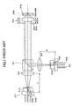
Shown in FIG. 1 is an outline of an optical
system of an optical pickup apparatus of a conventional
CD/DVD. The optical system of the optical pickup
apparatus comprises a DVD hologram unit 311, a coupling
lens 310, a beam splitter 321 and objective lenses 142a
and 142b that are arranged along a main line in that
order. On the other hand, a CD hologram unit 312, a
coupling lens 320 and a beam splitter 121 are arranged
along a line perpendicular to the main line in that
order toward the beam spritter121. The optical system
also comprises an actuator 314 that drives objective
lenses 342a and 342b.
The DVD hologram unit 311 integrally
incorporates a light source 311L, a hologram 311h for
separating a signal light from a light reflected by a
disc and a light-receiving element 311p for detecting a
signal. Similarly, the CD hologram unit 312 integrally
incorporates a light source 312L, a hologram 312h and a
light-receiving element 312p.
The objective lenses 342a and 342b differ
from CD to DVD. On the sides of the light sources 311L
and 312L of the objective lenses 342a and 342b, an
aperture 341a for DVD and an aperture 314b for CD are
arranged with respect to the objective lenses 342a and
342b, respectively. The apertures 341a and 341b are
shared by using an opening of an objective lens holder.
It should be noted that the objective lenses
342a and 342b and the apertures 341a and 341b are
integrally driven by the lens actuator 314 in a focusing
direction and a tracking direction. It should be noted
that a DVD disc 315a is indicated by solid lines and a
CD disc 315b is indicated by dotted lines. Moreover,
the coupling lenses 310 and 320 are different in their
aperture and a light taking angle of the light beam, and,
thus, lenses having different focal distances are used
for each light sources 311L and 312L.
If a focal distance of the coupling lens 310
is set to f1, and a focal distance of the coupling lens
320 is se to f2, an optical path length of equal to or
longer than f1 or f2, must be provided before incident
on the beam splitter 321, which causes a problem that
the optical system is increased in its size. Moreover,
if the coupling lenses 310 and 320 are made common, a
coupling efficiency of one of the light sources is
decreased, which causes a problem in that a spot power
on the discs 315a and 315b is decreased.
This is because a spot diameter is influenced
by an optical amount ratio (RIM) at a periphery of the
aperture with respect to the center of the optical axis,
other than the above-mentioned wavelength and numerical
aperture. Although the spot diameter decreases as the
RIM increases, a coupling efficiency of effectively
converging the light beam from the light source on a
surface of the disc is decreased, which causes a problem
in that a power is not sufficient and a recording and
reproducing speed is decreased. It should be noted that
in a normal optical disc system, for example, a design
target value of the RIM is determined as follows.
| minimum RIM |
| CD | 15% |
| DVD | 30% |
| Blu-ray/AOD | 50% |
If a coupling lens is shared by DVD and AOD
having the same NA, and if a focal distance of the
coupling lens is set to 50% of RIM of AOD, the focal
distance on the DVD side is also 50%, which decreases
the coupling efficiency of DVD.
Moreover, if a focal distance of the coupling
lens is set to 30% of DVD, the focal distance on the AOD
side is also about 30%, which increases the spot
diameter. Further, a combination of different numerical
apertures causes a problem that the above-mentioned
problems become severer.
The following patent document 1 discloses an
optical disc drive apparatus which solves the above-mentioned
problem by providing a condensing lens on one
of the sides of the two light sources. The optical disc
drive apparatus of the patent document 1 has a
converging optical system between a dichroic prism and a
second light source having a condensing lens on one of
the sides of two light sources, the converging optical
system converting a spreading angle of a diverging light
beam into a smaller spreading angle and leading the
light beam to the dichroic prism.
Moreover, as a conventional technique to
correct a chromatic aberration or a spherical aberration,
the following patent document 2 discloses an example to
drive a group of coupling lenses. Specifically, by
configuring and arranging one of two lens elements
movable along an optical axis by driving a group of
coupling lenses, a fluctuation of spherical aberration
generated on each optical surface in the converging
optical system, especially, the optical surface of an
objective lens can be corrected.
Since the technique disclosed in the patent
document 2 can correct in realtime a spherical
aberration generated in an objective lens due t a
variation in a thickness of a transparent substrate of
an optical information recording medium, a small
fluctuation in an oscillation wavelength of a laser
light source or a change in temperature and humidity, an
appropriate spot can be formed on an information
recording surface of the optical information recording
medium.
As for the objective lens, a multi-wavelength
compatible lens having a diffraction grating on a lens
surface has been put into practice, and a tree-wavelength
compatible diffraction lens handling the
Blue-ray or AOD has been developed. However, with
respect to the coupling lens, in order to optimize the
coupling efficiency of each light source, it is
necessary to use lenses having different distance for
each light source since the numerical aperture and the
light taking angle of the light beam differ for each
light source, and, thereby, it is difficult to make the
coupling lens common to a plurality of light sources.
Thus, the following patent document 3
discloses an optical pickup apparatus solving the above-mentioned
problem, which comprises: at least two laser
light sources of a first laser light source oscillating
at a wavelength in a range of 620 nm to 680 and having
an auxiliary lens between an optical synthesis component
and a light source to converge and diverge a light beam
and a second laser light source oscillating at a
wavelength in a range of 750 nm to 810 nm; a collimator
lens provided for converting the light beams projected
from the first and second laser light sources into
substantially parallel light beams; and an optical
component provided in an optical path between the first
and second laser light sources and the collimator lens
so as to synthesize optical paths of the light beams
projected from the first and second laser light sources,
wherein a first auxiliary lens diverging the light beam
is located in an optical path between the optical
synthesis component and the first laser light source,
and a second auxiliary lens converging the light beam is
located in an optical path between the optical synthesis
component and the second laser light source.
Moreover the patent document 2 discloses an
optical pickup apparatus that is capable of correcting a
fluctuation of a spherical aberration generated on each
optical surface in a light converging system, especially,
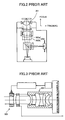
on the optical surface of a lens 301, as shown in FIG. 2,
by causing at least one of lenses 302a and 302b
constituting a coupling lens 302 movable along a
direction of the optical axis. Since the technique
disclosed in the patent document 2 can correct in
realtime a spherical aberration generated in an
objective lens due t a variation in a thickness of a
transparent substrate of an optical information
recording medium, a small fluctuation in an oscillation
wavelength of a laser light source or a change in
temperature and humidity, an appropriate spot can be
formed on an information recording surface of the
optical information recording medium.
Moreover, when performing recording or
reproduction on a multi-layer optical disc, a spherical
aberration is generated due to variation in the
thickness of layers, which causes a signal degradation
due to enlargement of a converged light spot. For this
reason, in an optical pickup performing recording or
reproduction on a multi-layer optical disc, means for
correcting the spherical aberration generated due to a
variation in the substrate thickness is provided. For
example, as a correction by a beam expander, the
following patent document 4 discloses a technique to
correct the spherical aberration due to a variation in a
substrate thickness by changing an interval of the
lenses of a beam example located between an objective
lens 304 and a coupling lens 305 along an optical axis
of the beam expander as shown in FIG 3.
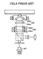
Moreover, as a correction by movement of a
coupling lens, the following patent document 5 discloses
a technique to correct the spherical aberration due to a
variation in a substrate thickness by moving a coupling
lens 308 located between an objective lens 306 and a
light source 7 as shown in FIG. 4.
The technique disclosed in the above-mentioned
patent document 1 is not applicable to a structure in
which two light sources are located close to each other
and mounted in one package. Additionally, there is a
problem in that a chromatic aberration and a spherical
aberration generated by a fluctuation in the wavelength
of the light source and a variation in a substrate
thickness of a multi-layer disc and a disc cannot be
corrected.
Additionally, the technique disclosed in the
above-mentioned patent document 2 has a problem in that
only one light source is used and it is difficult to
provide a plurality of optical information recording
media.
Moreover, in the above-mentioned patent
document 2, there is a problem in that it is difficult
to handle a plurality of optical information recording
media since there is provided only one light source.
In the above-mentioned patent document 3, the
above-mentioned problem is solved by providing a
converging lens and a diverging lens to each of the two
light sources. Although the number of lenses is
increased as compared to a conventional example in which
a coupling lens is provided to each light source, the
optical pickup apparatus can be reduced in its size
since the converging lens and the diverging lens are
located in a diverging optical path of each light source.
However, there still is a problem in that a correction
of a chromatic aberration and a spherical aberration due
to a variation in a substrate thickness of a disc, a
multi-layer disc or a fluctuation in a wavelength cannot
be achieved, which correction is needed with reduction
in the wavelength and increase in numerical aperture.
As usual means for correcting these
aberrations, there is considered a method in which a
two-group structure expander lens is inserted between a
coupling lens and an objective lens. However, such a
method may increase a number of component parts, which
increases the size of the entire apparatus.
Additionally, there is a problem in that a spot power on
a disc surface is decreased due to a decrease in a
transmittance of a light beam, which may cause
difficulty in achieving high-speed recording.
In the above-mentioned patent document 4, a
spherical aberration can be corrected by changing a
magnification of a light beam incident on an objective
lens. However, there is a problem, in this structure,
that the optical pickup of this structure is not
suitable for an optical disc drive, which requires
miniaturization, since a number of lenses located in the
optical system is large.
In the above-mentioned patent document 5,
there is a problem in that it is difficult to achieve a
correction of a spherical aberration since the
magnification change of the coupling lens is large and a
drive amount (distance of movement) must be very small.
SUMMARY OF THE INVENTION
It is a general object of the present
invention to provide an improved and useful optical
pickup apparatus in which the above-mentioned problems
are eliminated.
A more specific object of the present
invention is to provide an optical pickup apparatus
having a plurality of light sources, which can couple
the light beams from the light sources efficiently with
a simple structure, and is capable of correcting a
chromatic aberration and a spherical aberration
generated by a fluctuation in wavelength of the light
sources or a variation in a thickness of a substrate of
an optical disc.
In order to achieve the above-mentioned
objects, there is provided according to the present
invention an optical pickup apparatus for
recording/reproducing information on/from an optical
information recording medium by converging a light beam
from a light source onto a recording surface of the
optical information recording medium, the optical pickup
apparatus comprising: a plurality of light sources
corresponding to a plurality of optical information
recording media, respectively; a coupling lens including
a plurality of groups of lenses common to the plurality
of light sources so as to converge a light beam from
each of the light sources; an aperture capable of
changing an aperture diameter for the light beam, which
has been converged by the coupling lens, in accordance
with one of the light sources from which the light beam
is emitted; an objective lens converging the light beam,
which has passed through the aperture, onto a recording
surface of one of the optical information recording
media corresponding to the one of the light sources that
emits the light beam; and a lens moving mechanism moving
at least one group of lenses from among the plurality of
groups of lenses of the coupling lens in a direction of
an optical axis thereof so that a ratio of an intensity
of the light beam in a peripheral part of the aperture
of the light beam to an intensity of the light beam at
the center of the optical axis is set to a predetermined
value for each light source.
Accordingly, it becomes possible to determine
a travel distance of the coupling lens based on the
aperture diameter and an optimum taking angle of the
light beams from the light sources, which enables
obtaining an optimum spot diameter for each light source
and a highest coupling efficiency. Thus, it is possible
to provide a high-speed and high-performance multi-wavelength
optical pickup apparatus having a simple
structure.
In the optical pickup apparatus according to
the present invention, the objective lens may be common
to the plurality of light sources. Accordingly, even if
the coupling lens and the objective lens are common to
the light sources, an optimum coupling efficiency can be
set for each light source and the optical system can be
miniaturized.
In the optical pickup apparatus according to
the present invention, at least two of the plurality of
light sources may be located with an light-emitting pint
interval therebetween being equal to or smaller than
several hundreds micrometers, and at least two groups of
lenses of the coupling lens may be provided with the
lens moving mechanisms that moves the at least two
groups of lenses, respectively, in the direction of the
optical axis in accordance with the aperture diameter
corresponding to each of the at least two of the
plurality of light sources. Accordingly, an optimum
coupling efficiency can be set for each light source and
the optical system can be miniaturized in this invention,
unlike a conventional optical system in which two light
sources are incorporated into one package but a decrease
in a coupling efficiency of one of the light sources is
not avoidable.
In the optical pickup apparatus according to
the present invention, at least two of the plurality of
light sources have different wavelengths, and after the
lens moving mechanism moves at least one group of lenses
from among the plurality of groups of lenses in the
direction of the optical axis in accordance with the
aperture diameter of the aperture, the lens moving
mechanism further moves the at least one group of lenses
from among the plurality of groups of lenses in the
direction of the optical axis in accordance with the
wavelengths of the at least two of the plurality of
light sources.
Accordingly, while providing an optimum
coupling efficiency is provided to each light source by
moving the coupling lens, a chromatic aberration can be
corrected and a best beam spot can be obtained. Thus,
it is possible to provide a high-speed and high-performance
multi-wavelength optical pickup apparatus
having a simple structure.
In the optical pickup apparatus according to
the present invention, at least one of the plurality of
optical information recording media may have a plurality
of recording surfaces in a layered structure, and after
the lens moving mechanism moves at least one group of
lenses from among the plurality of groups of lenses in
the direction of the optical axis in accordance with the
aperture diameter of the aperture, the lens moving
mechanism may move the at least one group of lenses from
among the plurality of groups of lenses in the direction
of the optical axis in accordance with the plurality of
recording surfaces. Accordingly, a spherical aberration
generated in a multi-layer disc can be corrected, and an
optimum beam spot can be obtained. Thus, it is possible
to provide a high-speed and high-performance multi-wavelength
optical pickup apparatus having a simple
structure.
In the optical pickup apparatus according to
the present invention, at least one of the plurality of
optical information recording media may have has a
light-transmitting layer, and after the lens moving
mechanism moves at least one group of lenses from among
the plurality of groups of lenses in the direction of
the optical axis in accordance with the aperture
diameter of the aperture, the lens moving mechanism may
further move the at least one group of lenses from among
the plurality of groups of lenses in the direction of
the optical axis in accordance with a variation in
thickness of the light-transmitting layer. Accordingly,
it becomes possible to correct a spherical aberration
even in an optical disc having a light-transmitting
layer whose thickness has variation, which enables an
optimum beam spot being obtained. Thus, it is possible
to provide a high-speed and high-performance multi-wavelength
optical pickup apparatus having a simple
structure.
In the optical pickup apparatus according to
the present invention, after the lens moving mechanism
moves at least one group of lenses from among the
plurality of groups of lenses in the direction of the
optical axis in accordance with the aperture diameter of
the aperture, the lens moving mechanism further moves
the at least one group of lenses from among the
plurality of groups of lenses in the direction of the
optical axis in accordance with a fluctuation in
wavelength of one of the plurality of light sources that
emits the light beam. Accordingly, it becomes possible
to correct a chromatic aberration even in a case where a
wavelength of each light source fluctuates due to a
temperature change, which enables an optimum beam spot
being obtained. Thus, it is possible to provide a high-speed
and high-performance multi-wavelength optical
pickup apparatus having a simple structure.
The optical pickup apparatus according to the
present may further comprise spherical aberration
detecting means for detecting a spherical aberration
with respect to at least one of the plurality of light
sources. Accordingly, it becomes possible to
comprehensively correct a chromatic aberration generated
due to a variation in a wavelength of the light source
or a wavelength fluctuation due to a temperature change
and also a spherical aberration generated due to a
multi-layer structure of an optical disc or a variation
in thickness of a light-transmitting layer, which
enables an optimum beam spot being obtained. Thus, it
is possible to provide a high-speed and high-performance
multi-wavelength optical pickup apparatus having a
simple structure.
In the optical pickup apparatus according to
the present invention, the coupling lens may be an
achromatic lens that corrects a chromatic aberration in
a beam spot formed on the recording surface by
converging the light beam emitted from at least one of
the light sources. Accordingly, it becomes possible to
correct a chromatic aberration generated due to
instantaneous wavelength fluctuation caused by a change
in an output power of each light source, which enables
an optimum beam spot being obtained. Thus, it is
possible to provide a high-speed and high-performance
multi-wavelength optical pickup apparatus having a
simple structure.
The optical pickup apparatus according to the
present invention may further comprise a lens located
between one of the light sources and the coupling lens
so as to change a degree of divergence of the light beam
from the one of the light sources. Accordingly, by
providing the additional lens, an amount of movement of
the coupling lens can be reduced, which enables the
optical system being miniaturized.
Additionally, there is provided according to
another aspect of the present invention an optical disc
drive apparatus comprising: a drive mechanism that
drives an optical information recording medium; and one
of the optical pickup apparatus mentioned above.
Additionally, there is provided according to
another aspect of the present invention an optical
pickup apparatus for recording/reproducing information
on/from an optical information recording medium by
converging a light beam from a light source onto a
recording surface of the optical information recording
medium, the optical pickup apparatus comprising: a
plurality of light sources corresponding to a plurality
of optical information recording media, respectively; an
optical path synthesizing and separating component that
synthesizes and separates light beams from the plurality
of light sources; a coupling lens including a plurality
of groups of lenses common to the plurality of light
sources so as to converge a light beam from each of the
light sources; and an objective lens converging the
light beam, which has passed through the aperture, onto
a recording surface of one of the optical information
recording media corresponding to the one of the light
sources that emits the light beam, wherein the plurality
of groups of lenses constituting the coupling lens is
located in a direction of an optical axis of at least
one of the light sources with the optical path
synthesizing and separating component interposed
therebetween; and a lens moving mechanism moves at least
one group of lenses from among the plurality of groups
of lenses of the coupling lens in a direction of an
optical axis thereof in accordance with an aperture
diameter of the aperture.
Accordingly, while realizing an optimum
coupling efficiency for each light source, the optical
system for coupling can be miniaturized. Additionally,
with respect to the light source optical path requiring
a spherical aberration and a chromatic aberration, there
is no need to add other components to perform such a
correction, thereby achieving miniaturization and high-speed
recording.
Moreover, since at least one group of lenses
from among the plurality of groups of lenses are moved
so as to change a magnification of the light beam to be
incident on the objective lens, a spherical aberration
can be corrected. Furthermore, since lens moving
mechanism has a function of a coupling lens, a number of
optical components is reduced, which miniaturizes the
entire optical system. In addition, since the coupling
lens is shared by the plurality of light sources, the
number of optical components can be reduced further,
which further miniaturizes the entire optical system.
Since the optical beam synthesizing means is provided, a
space for arranging other optical components can be
reserved between the light sources and the coupling lens.
Moreover, it becomes possible to correct a
spherical aberration with respect to light beams from a
plurality of light sources by moving the coupling lens
which the light beams form the plurality of light
sources pass through. Furthermore, for example, if a
first light beam synthesizing component for a first
light source and a second light source is located
between at least one group of lenses of the coupling
lens and the objective lens, and further at least one
group of lenses of the coupling lens for a third light
source is located between the third light source and a
second light beam synthesizing component, an optical
pickup in which such a third light source is integrally
incorporated can be provided without increasing the
number of optical beam transmitting components of the
first and second light sources. Therefore, it is
possible to provide an optical pickup apparatus, which
is capable of correcting a chromatic aberration and a
spherical aberration generated due to a wavelength
fluctuation of each light source, a multi-layered
structure disc, a variation in a thickness of a disc
substrate, while efficiently coupling an optical beam
from each light source with a simple structure.
In the optical pickup apparatus according to
the above-mentioned invention, the lens moving mechanism
may be provided to the lens having a maximum absolute
value of a focal distance from among the plurality of
groups of lenses. Accordingly, an accuracy of driving
lenses when correcting a spherical aberration can be
relaxed.
In the optical pickup apparatus according to
the above-mentioned invention, one of the optical
information recording media may have a plurality of
recording surfaces in a layered structure, and the lens
moving mechanism may move at least one group of lenses
of the coupling lens in the direction of the optical
axis so as to converge each light beam onto a respective
one of the recording surfaces. Accordingly, a degree of
divergence of the light beam to be incident on the
objective lens can be changed so as to correct a
spherical aberration and a chromatic aberration, by
moving at least one group of lenses of the coupling lens
in the direction of the optical axis in response to a
difference in substrate thickness of each layer, a
manufacturing tolerance of substrate thickness, a
wavelength fluctuation of each light source. Thus, an
excellent beam spot can always be formed, which improves
a recording and reproducing characteristic.
In the optical pickup apparatus according to
the above-mentioned invention, one of the optical
information recording media may have a light-transmitting
layer, and the lens moving mechanism may
move at least one group of lenses of the coupling lens
in the direction of the optical axis in accordance with
a variation in thickness of the light-transmitting layer.
Accordingly, a degree of divergence of the light beam to
be incident on the objective lens can be changed so as
to correct a spherical aberration and a chromatic
aberration, by moving at least one group of lenses of
the coupling lens in the direction of the optical axis
in response to a difference in substrate thickness of
each layer, a manufacturing tolerance of substrate
thickness, a wavelength fluctuation of each light source.
Thus, an excellent beam spot can always be formed, which
improves a recording and reproducing characteristic.
Additionally, by moving the coupling lens based on
information of a result of detection of a substrate
thickness of an optical disc, a spherical aberration
correction can be performed on an optical disc having a
multi-layer structure.
In the optical pickup apparatus according to
the above-mentioned invention, the lens moving mechanism
may move at least one group of lenses of the coupling
lens in the direction of the optical axis in accordance
with a wavelength fluctuation of each of the light
sources. Accordingly, a degree of divergence of the
light beam to be incident on the objective lens can be
changed so as to correct a spherical aberration and a
chromatic aberration, by moving at least one group of
lenses of the coupling lens in the direction of the
optical axis in response to a difference in substrate
thickness of each layer, a manufacturing tolerance of
substrate thickness, a wavelength fluctuation of each
light source. Thus, an excellent beam spot can always
be formed, which improves a recording and reproducing
characteristic.
In the optical pickup apparatus according to
the above-mentioned invention, each of the coupling lens
and the objective lens may be an achromatic lens system.
Accordingly, a chromatic aberration can be eliminated
even when a wavelength is instantaneously changed such
as in a mode hop, thereby reducing errors during
recording and reproduction. Additionally, when an
anamorphic element such as a beam shaping prism is
arranged between the coupling lens and the objective
lens, it is required to achromatic function to cause a
light incident on the anamorphic lens to be a parallel
light. Thus, the above-mentioned structure is needed so
as to prevent generation of astigmatism in the
anamorphic element.
In the optical pickup apparatus according to
the above-mentioned invention, an entire system
including the coupling lens and the objective lens may
be an achromatic lens system. Accordingly, a chromatic
aberration can be corrected even when a refraction lens
is used for the objective lens. Thus, an optical system
having a good light use efficiency and no chromatic
aberration can be realize, and it is possible to achieve
high speed and high stabilization. Moreover, it also
becomes possible to reduce a chromatic aberration
generated due to a short time wavelength fluctuation
with respect to the optical system of each light source.
The optical pickup apparatus according to the
above-mentioned invention may further comprise an
aspheric aberration detecting means for detecting an
aspheric aberration in a reflected light from one of the
recording surfaces of one of the optical information
recording media onto which a light beam from at least
one of the light sources is converged. Accordingly, a
chromatic aberration can be corrected even when a
refraction lens is used for the objective lens. Thus,
an optical system having a good light use efficiency and
no chromatic aberration can be realize, and it is
possible to achieve high speed and high stabilization.
Moreover, it also becomes possible to reduce a chromatic
aberration generated due to a short time wavelength
fluctuation with respect to the optical system of each
light source. Accordingly, since the direction of
movement and the amount of movement of the coupling lens
can be recognized instantaneously by the spherical
aberration detection signal, there is no need to seek
for an optimum position. Thus, a spherical aberration
and a chromatic aberration can always be corrected for
any cause, thereby enabling a high speed and excellent
recording and reproduction.
In the optical pickup apparatus according to
the above-mentioned invention, one group of lenses
located closest to the light sources may serve as a
concave lens. Accordingly, since a rim light intensity
(RIM) of a light beam incident on the objective lens can
be increased by making a lens closer to a light source
than the optical path synthesizing and separating
mechanism as a concave lens so as to increase a
diverging angle of a diverging light from the light
source concerned, a beam spot diameter on a disc is
decreased, which results an improvement in the recording
and reproducing performance. Moreover, by combining
with a convex lens closer to the objective lens than the
optical path synthesizing and separating mechanism, an
achromatic design can be made even if it is a single
lens.
In the above-mentioned optical pickup
apparatus, λA<λB may be satisfied where λA is a
wavelength of a light beam that transmits the concave
lens, and λB is a wavelength of a light beam that does
not transmit the concave lens. Accordingly, if the
light source on the side of the concave lens is set to
one having a shorter wavelength than the other light
source, an effect of increasing the RIM becomes more
remarkable due to a divergence action of the concave
lens.
In the optical pickup apparatus according to
the above-mentioned invention, one group of lenses
located closest to the light sources may serve as a
convex lens. Accordingly, by making the group of lenses
of the coupling lens on the side of the objective lens
as a convex lens, an optical path for coupling can be
reduced, which miniaturizes the optical pickup apparatus.
Additionally, since a light beam of the light source
closest to the convex lens is coupled up to a smaller
RIM, the coupling efficiency and a power on the disc
surface are increased, which realizes high-speed
recording.
In the above-mentioned optical pickup
apparatus, λB<λA may be satisfied where λA is a
wavelength of a light beam that transmits the convex
lens, and λB is a wavelength of a light beam that does
not transmit the convex lens. Accordingly, if the light
source on the side of the convex lens is set to one
having a longer wavelength than the other light source,
the above-mentioned effect can be more remarkable due to
a convergence action of the convex lens.
In the optical pickup apparatus according to
the present invention, the at least one group of lenses
moved by the lens moving mechanism in the direction of
the optical axis may be located between the light
sources and the optical path synthesizing and separating
component. Accordingly, since a degree of divergence
can be changed only for a light beam of a light source
that require an adjustment, other light sources can
always be fixed in positions, which provides a stable
performance.
In the optical pickup apparatus according to
the present invention, the at least one group of lenses
moved by the lens moving mechanism in the direction of
the optical axis may be located between the optical path
synthesizing and separating component and the objective
lens. Accordingly, if there are a plurality of light
sources that emit light beams requiring an adjustment,
the lens moving mechanism can be shared with the
plurality of light sources, which enables
miniaturization of the optical pickup apparatus.
The optical pickup apparatus according to the
present invention may further comprise beam shaping
means provided between the light sources and one group
of lenses arranged closest to the light sources.
Accordingly, by arranging the beam shaping means
utilizing the space between the coupling lens and the
light source, a circular light beam of a semiconductor
laser can be achieved, which increases a light use
efficiency (a coupling efficiency).
The optical pickup apparatus according to the
present invention may further comprise discriminating
means for discriminating a kind of each of the optical
information recording media, and the lens moving
mechanism may move at least one group of lenses that
constitute the coupling lens in the direction of the
optical axis in accordance with the king of each of the
optical information recording media. Accordingly, by
discriminating a kind of an optical disc through the
discriminating means and moving the coupling lens based
on information regarding the discrimination, a spherical
aberration correction can be performed with respect to
optical discs having various substrate thicknesses.
In the optical pickup apparatus according to
the present invention, a direction of the optical axis
of the coupling lens or the objective lens may be set so
that a spherical aberration generated in each optical
surface is minimized in accordance with an oscillation
wavelength of each of the light sources. Accordingly, a
wavefront aberration in an optical system can be
optimized by adjusting the positions of the group of
lenses in the direction of the optical axis in
accordance with a variation in oscillation wavelength of
a light source. Additionally, for example, a wavefront
aberration in the optical system of each light source
can be optimized by changing positions of at least one
group of lenses constituting the coupling lens between
when a first light source is selected and when a second
light source is selected.
Additionally, there is provided according to
another aspect of the present invention an optical disc
drive apparatus comprising: a drive mechanism for
driving an optical information recording medium; and an
optical pickup apparatus according to the above
mentioned invention that performs recording and
reproducing operations on the optical information
recording medium driven by the drive mechanism.
Accordingly, an optical disc drive apparatus can be
provided that can provide one of the above-mentioned
effects. Additionally, an optical disc drive apparatus
can be realized that can efficiently couple light beams
from a plurality of light beams with a simple structure,
and that can correct a chromatic aberration and a
spherical aberration generated due to a variation in
thickness of a disc substrate, a multi-layer structure
of a disc and a wavelength fluctuation of a light
surface. Further, a miniaturized optical disc drive
apparatus can be provided.
Other objects features and advantages of the
present invention will become more apparent from the
following detailed description when read in conjunction
with the accompanying drawings.
BRIEF DESCRIPTION OF THE DRAWINGS
FIG. 1 is an illustration of an optical system
of a conventional optical pickup apparatus;
FIG. 2 is an illustration of an optical system
of another conventional optical pickup apparatus;
FIG. 3 is an illustration of an optical system
of a further conventional optical pickup apparatus;
FIG. 4 is an illustration of an optical system
of yet another conventional optical pickup apparatus;
FIGS. 5A and 5B are illustrations of an
optical system of an optical pickup apparatus according
to a first embodiment of the present invention;
FIGS. 6A and 6B are illustrations for
explaining a focal distance of a coupling lens system
shown in FIGS. 5A and 5B;
FIGS. 7A and 7B are illustrations of an actual
design of the coupling lens system shown in FIGS. 5A and
5B;
FIG. 8A is a plan view of an actuator shown in
FIGS. 5A and 5B;
FIG. 8B is a cross-sectional view of the
actuator shown in FIG. 8A;
FIGS. 9A and 9B are illustrations of a
variation of the optical system of the optical pickup
apparatus shown in FIGS. 5A and 5B;
FIG. 10 is an illustration of another
variation of the optical system of the optical pickup
apparatus shown in FIGS. 5A and 5B;
FIG. 11 is an illustration of another
variation of the optical system of the optical pickup
apparatus shown in FIGS. 5A and 5B;
FIG. 12 is an illustration of a further
variation of the optical system of the optical pickup
apparatus shown in FIGS. 5A and 5B;
FIG. 13 is an illustration of yet another
variation of the optical system of the optical pickup
apparatus shown in FIGS. 5A and 5B;
FIG. 14 is an illustration of a basic
structure of an optical system of an optical pickup
apparatus according to the present invention;
FIG. 15 is an illustration of an optical
system of an optical pickup apparatus according to a
second embodiment of the present invention;
FIGS. 16A and 16B are illustrations for
explaining focal distances of a coupling lens system
shown in FIG. 15;
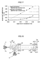
FIG. 17 is a graph showing a wavefront
aberration reducing effect when a spherical aberration
is corrected based on the structure shown in FIG. 15;
FIG. 18 is an illustration of a variation of
the optical system of the optical pickup apparatus shown
in FIG. 15;
FIG. 19 is an illustration of another
variation of the optical system of the optical pickup
apparatus shown in FIG. 15;
FIG. 20 is an illustration of a further
variation of the optical system of the optical pickup
apparatus shown in FIG. 15;
FIG. 21 is an illustration of yet another
variation of the optical system of the optical pickup
apparatus shown in FIG. 15;
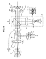
FIG. 22 is a block diagram of optical disc
discriminating means provided in the optical pickup
apparatus; and
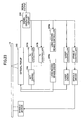
FIG. 23 is a block diagram of an optical disc
drive apparatus provided with the optical pickup
apparatus according to the present invention.
DETAILED DESCRIPTION OF THE PREFERRED EMBODIMENTS
(First Embodiment)
A description will be given of an optical
pickup apparatus according to a first embodiment of the
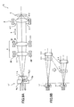
present invention. FIGS. 5A and 5B show an optical
system provided in the optical pickup apparatus
according to the present invention.
The optical system 1 shown in FIGS. 5A and 5B
comprises a first hologram unit 11, a beam splitter 2, a
coupling lens system 3 and an actuator 4 that are
arranged on a straight line in that order. The optical
system 1 also comprises a second hologram unit 12, which
faces the beam splitter 2 and has an optical axis
perpendicular to the straight line. It should be noted
that the first coupling lens system 3 includes a first
coupling lens (a group of lenses) 31, a second coupling
lens (a group of lenses) 32, a single-axis actuator 33
for driving the second coupling lens 32 in a direction
of the optical axis, etc. The actuator 4 is provided
with apertures (opening parts) 41a and 41b, objective
lenses 42a and 42b, a holder 43, etc., so as to drive
the objective lenses 42a and 42b.
It should be noted that the first hologram
unit 11 is provided with a laser light source 11L, a
hologram element 11h for acquiring a necessary signal by
diffracting a light reflected by a disc, and a light-receiving
element 11p for generating various signals.
Similarly, the second hologram unit 12 is provided with
a laser light source 12L, a hologram element 12h for
acquiring a necessary signal by diffracting a light
reflected by a disc, and a light-receiving element 12p
for generating various signals.
FIG. 5A is an illustration showing a state
where the first hologram unit 11 emits a light. In FIG.
5A, the diverging light from the first hologram unit 11
transmits the beam splitter 2 and transmits the first
coupling lens 31, and, then, transmits the coupling lens
32. When the focal distance of the coupling lens system
is fa and the light-emitting point (the laser light
source 11L) is at a focal point, the transmitted light
becomes a parallel light, and the parallel light is
limited in its aperture diameter and is converged onto a
recording surface of a DVD (optical information
recording medium) 5a by the objective lens 42a. The
light reflected by the DVD 5a passes through the
objective lens 42a, the second coupling lens 32, the
first coupling lens 31 and the beam splitter 2, and,
then, the light is incident on the hologram unit 11
again. The light-receiving unit 11p of the hologram
unit 11 generates a track signal, a focus signal, an
information signal, etc., by the light incident on the
hologram unit 11.
It should be noted that the objective lens 42a
is servo-controlled by the two-axis actuator 4 in
accordance with the track signal and the focus signal so
as to form a light spot of a diffraction limit on the
DVD 5a by always following a movement of the disc.
FIG. 5B is an illustration showing a state
where the first hologram unit 12 emits a light. In FIG.
5B, the diverging light from the second hologram unit 12
transmits the beam splitter 2 and transmits the first
coupling lens, and, then, transmits the second coupling
lens 32. When the focal distance of the coupling lens
system is fb and the light-emitting point (the laser
light source 12L) is at a focal point, the transmitted
light becomes a parallel light, and the parallel light
is limited in its aperture diameter and is converged
onto a recording surface of a CD (optical information
recording medium) 5b by the objective lens 42b. The
light reflected by the CD 5b passes through the
objective lens 42b, the second coupling lens 32, the
first coupling lens 31 and the beam splitter 2, and,
then,'the light is incident on the hologram unit 12
again. The light-receiving unit 12p of the hologram
unit 12 generates a track signal, a focus signal, an
information signal, etc., by the light incident on the
hologram unit 12.
It should be noted that the objective lens 42b
is servo-controlled by the two-axis actuator 4 in
accordance with the track signal and the focus signal so
as to form a light spot of a diffraction limit on the CD
5b by always following a movement of the disc.
Here, since the second coupling lens 32 is
moves in the direction "a" of the optical axis the focal
distance fb of the coupling lens system 3 (the first
coupling lens 31, the second coupling lens 32) can be
changed from the focal distance fa of FIG. 5A. That is,
generally, the synthetic focal distance f in two thin
lens system is given by the following equation.
1/f=1/f1+1/f2-d/ (f1×f2)
Therefore, f is changeable by varying d.
When the light-emitting point (laser light
source 12L) of the second hologram unit 12 is located at
the focal distance fb of the coupling lens system 3, a
light transmitting the coupling lens system 3 and
traveling to the aperture 41b is a parallel light. Then,
the light is limited in its aperture diameter, and is
converged onto the recording surface of the CD 5b by the
objective lens 42b. When the light taking angle for
each of the two leaser light sources 11L and 12L, which
satisfies the aperture diameter and the RIM
specifications of the objective lenses 42a and 42b, is
determined, the focal distance f of the coupling lens
system 3 is given by the following equation.
f=/ (2×sin)
Accordingly, an optimum synthetic focal
distance f is acquired from an optimum value of with
respect to each of the laser light sources 11A and 12L
using the equations (1) and (2), and a value of the
distance d between the first coupling lens and the
second coupling lens is acquired in accordance with the
synthetic focal distance. Finally, a value of the
distance of the second coupling lens 32 to be moved can
be acquired.
When the light beam from the coupling lens
system 3 is non-parallel light, the distance d between
the first coupling lens and the second coupling lens can
be acquired using the same equations.
The following Table 1 shows an example of
specific design in the cases of AOD and DVD.
| | AOD | DVD |
| DIVERGING ANGLE OF LIGHT SOURCE (HALF VALUE) | 10° | 10° | // DIRECTION FOR SEMICONDUCTOR LASER |
| MINIMUM VALUE OF RIM | 50% | 30% |
| FOCAL DISTANCE (f) of OBJECTIVE LENS | 3mm | 3mm |
| NUMERICAL APERTURE | 0.65 | 0.65 |
| APERTURE DIAMETER | 3.9 | 3.9 | =2×f×NA |
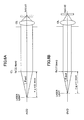
According to the Table 1 and FIG. 6A, it is
appreciated that the light taking angle aod of the
light from the laser light source for AOD is a half of
the diverging angle (half value of whole angle) of the
light source, that is, 5°. Therefore,
fa=3.9/ (2×sin5°)=22.4 mm is obtained according to the
equation (2).
On the other hand, in FIG. 6B, the light
taking angle dvd is given according to the following
equation based on a general formula of Gaussian
distribution.
dvd= [{ln(Ra)/ln(Rb)}×aod2] 1/2
If Ra=0.3, Rb=0.5 and dvd=6.6° in the
equation (3), fb=17.0 mm is given by the equation (2).
Moreover, if f1=12 mm and f2=-20 mm in the equation (1),
the values of the synthetic focal distances fa and fb
can be given near da=3 mm and db=6 mm, respectively.
FIGS. 7A and 7B show the coupling lens system
3 which is designed practically from the above results.
When the thickness of the coupling lens L1 is set to 2.0
mm, the thickness of the coupling lens L2 is set to 1.2
mm, and the focal distances of the lenses are set to
f1=12mm and f2=-20mm, the synthetic focal distances are
fa=22.4 mm and fb=17.0 mm near da=1.5 mm and db=4.5 mm,
respectively.
That is, by moving the coupling lens L1 in a
direction away from the coupling lens L2 by 3 mm, the
minimum value of RIM to each aperture diameter can be
acquired, which satisfies the conditions.
In the meantime, the objective lenses 42a and
42b are mounted on the two-axis actuator 4 of a rotary
switching type as shown in FIGS. 8A and 8B.
That is, the actuator 4 has a disk-shaped
holder 43 having tow through holes formed in a direction
of the thickness thereof, and the apertures 41a and 41b
and the objective lenses 42a and 42b are provided in the
through holes, respectively. The holder 43 is rotatable
in a direction indicated by arrows B about a shaft 44
penetrating at the center of the holder 43. Moreover, a
coil 45 is provided in a peripheral portion of the
holder 43. The coil 45 has a function of a track coil
and a focus coil. Further, there is provided a magnet
outside the coil 45 at a position close to the coil 45
with a predetermined gap therebetween. An upward-directing
mirror 47 is provided under the holder 43.
In the thus-constructed actuator 4, a light
beam is reflected by the upward-directing mirror 47, and
is incident on the objective lens 42 through the
aperture 41a. The actuator 4 performs switching between
the objective lenses 42a and 42b and a tracking servo
operation by rotating in the direction B.
Additionally, the holder 43 moves in a
direction indicated by arrows C by a magnetic force by
the coil 45 and a magnet 46 so as to perform a focus
servo operation.
The optical pickup apparatus performs
recording and reproduction on both the DVD 5a and the CD
5b by converging the light beams from the laser light
sources 11L and 12L onto the DVD 5a and the CD 5b (both
are optical information recording media), respectively,
as shown in FIGS. 5A and 5B. The optical pickup
apparatus comprises: the laser light sources 11L and 12L
corresponding to the DVD 5a and the CD 5b; the coupling
lens system (a coupling lens) 3 including the first
coupling lens (a group of lenses) 31 and the second
coupling lens (a group of lenses) 32 that are common to
the laser light sources 11L and 12L so as to converge
the light beams from the laser light sources 11L and 12L
by the first coupling lens 31 and the second coupling
lens 32; the apertures (opening parts) 41a and 41b that
can change the aperture diameter in accordance with the
laser light sources 11L and 12L; the objective lenses
42a and 42b that converge the light beams passed through
the apertures 41a and 41b onto the recording surfaces of
the DVD 5a and the CD 5b, respectively; and the actuator
(lens moving means) 33 for moving at least one of the
first coupling lens 31 and the second coupling lens 32
in accordance with the aperture diameters of the
apertures 41a and 41b.
It should be noted that, in the present
invention, the number of the laser light sources of the
optical system is not limited to two. Additionally, the
number of groups of the coupling lens system is not
limited to two.
FIG. 9A is an illustration showing an optical
system 1a of an optical pickup apparatus provided with a
hologram unit 11' having two laser light sources 11L1
and 11L2. In the optical system 1a, the hologram 11h
and the light-receiving elements 11p are common to the
two laser light sources 11L1 and 11L2. It is configured
and arranged so that an optimum RIM and coupling
efficiency are acquired for each of the two laser light
sources 11L1 and 11L2 by driving independently the first
coupling lens 31 and the second coupling lens 32 by the
single-axis actuators 34 and 33, respectively. In this
respect, a distance between the two laser light sources
11L1 and 11L2 is set to a value equal to or smaller than
several hundreds µm.
It should be noted that, in such a case, the
objective lenses 42a and 42b shown in FIGS. 5A and 5B
are made common as an objective lens 42 by causing one
of the incident light beams to be diverging light or
providing a diffraction grating on the lens surface to
make a diffraction lens. At this time, the apertures
41a and 41b are also made common as an aperture 41 by
using a wavelength filter having wavelength selectivity
or diffraction grating.
That is, the objective lenses 42a and 42b are
common to the laser light sources 11L and 12L.
Moreover, two laser light sources 11L and 12L
are arranged so that a distance between the light -
emitting points of both is set equal to or smaller
several hundreds µm, and the single-axis actuators (lens
moving means) 34 and 33 are provided for moving the
first coupling lens 31 and the second coupling lens 32
of the coupling lens system 3 in the direction "a" of
the optical axis in accordance with the aperture
diameters of the two laser light sources 11L and 12L,
respectively.
FIG. 9B is an illustration showing a state
where the first coupling lens 31 and the second coupling
lens 32 are moved by driving the single-axis actuators
34 and 33 independently.
In the meantime, when light source wavelengths
are different such as the case of AOD and DVD, a color
aberration is generated in the lens system and the
substrate even if the numerical aperture (NA) and the
substrate thickness are the same. The color aberration
can be corrected by making the light beam from the
coupling lens system 3 non-parallel by further moving
the first coupling lens 31 and the second coupling lens
32 by predetermined distances by the single-axis
actuators 34 and 33. Therefore, the coupling lens
system 3 can obtain the a good spot which always have no
aberration by being driven in consideration of the
chromatic aberration beforehand at the time of switching
the light source.
That is, the wavelengths of the two laser
light sources 11L and 12L are different from each other,
and after moving at least one group of lenses of the
first coupling lens 31 and the second coupling lens 32
by the single-axis actuator (lens moving means) 34 and
33 in accordance with the aperture diameters of the
apertures (opening parts) 41a and 41b, at least one
group of lenses of the first coupling lens 31 and the
second coupling lens 32 is moved further in the
direction "a" of the optical axis in accordance with the
wavelengths of the two laser light sources 11L and 12L.
It should be noted that the number of the laser light
sources is not limited to two.
As shown in FIG. 10, in a case of an optical
information recording medium 5 having a plurality of
recording surfaces formed in layers, a spherical
aberration is generated in an optical system 1b of an
optical pickup apparatus as shown in FIG. 10 since the
thicknesses of the optical transmission layers are
different from each other. The spherical aberration can
be corrected by making the light beam from the coupling
lens non-parallel. If a thickness t of a first layer
Lay0 of the optical transmission layers is t0, the
spherical aberration generated by the first layer Lay0
is corrected beforehand by the objective lens 42 when
designing, and, thus, an the light beam from the
coupling lens system 3 is a parallel light. However, if
the thickness t of the second layer Lay1 of the optical
transmission layer is set to t1, a spherical aberration
corresponding to the difference between t1 and t0 is
generated. At this time, the second coupling lens 32 is
moved by the single-axis actuator 33 in the direction
"a" of the optical axis and the light beam from the
coupling lens system 3 is a non-parallel light, which
causes the light beam canceling the spherical aberration
is incident on the objective lens.
Therefore, in the coupling lens system 3, a
good beam spot having no aberration can always be
obtained by the second coupling lens 32 being moved to
correct the spherical aberration when switching the
layers of the optical information recording medium 5.
That is, at least one optical information
recording medium 5 from among a plurality of information
recording media is formed in a layer structure to have
two recording layers Lay0 and Lay1, and after moving at
least one group of lenses of the first coupling lens 31
and the second coupling lens 32 in accordance with the
aperture diameter of the aperture (opening part) 41 by
the single-axis actuator (lens moving means) 33, at
least one group of lenses of the first coupling lens 31
and the second coupling lens 32 is moved further by the
single-axis actuator 33 in accordance with the plurality
of recording surfaces Lay0 and Lay1.
It should be noted that the number of
recording surfaces of the optical information recording
media 5 is not limited to two.
It should be noted that the thickness t of
each of the optical transmission layers of the optical
information recoding medium 5 varies from a design
thickness due to manufacturing tolerance, temperature
change, etc. A spherical aberration is generated due to
such variation, but such a spherical aberration can be
corrected by making the light beam from the coupling
lens system 3 non-parallel. Therefore, a thickness
measuring means (not shown in the figure) is provided in
the optical system 1b so as to measure the thickness t
of each optical transmission layer of the optical
information recording medium 5, and the coupling lens
system 3 is moved so as to correct the spherical
aberration in accordance with the measured value so that
a good beam spot having no aberration is always obtained.
That is, at least one optical information
recording medium 5 from among a plurality of optical
information recording media has two recording surfaces
Lay0 and Lay1, and after moving at least one group of
lenses of the first coupling lens 31 and the second
coupling lens 32 in accordance with the aperture
diameter of the aperture (opening part) 41 by the
single-axis actuator 33, at least one group of lenses of
the first coupling lens 31 and the second coupling lens
32 is moved further by the single-axis actuator 33 in
accordance with the variation in the thickness of the
optical transmission layers.
It should be noted that the number of
recording surfaces of the optical information recording
medium 5 is not limited to two.
Moreover, the wavelengths of the laser light
sources 11L and 12L fluctuate as design wavelengths as a
center of fluctuation due to changes in temperature and
output power. According to the wavelength fluctuation,
a chromatic aberration is generated in the lens system
or the substrate. The chromatic aberration can be
corrected by making the light beam from the coupling
lens system 3 non-parallel. Therefore, wavelength
measuring means (not shown in the figure) is provided in
the optical system 1b so as to measure the wavelength of
each of the laser light sources 11L and 12L, and the
coupling lens system 3 is moved so as to correct the
chromatic aberration in accordance with the measured
value so that a good beam spot having no aberration is
always obtained.
That is, after moving at least one group of
lenses of the first coupling lens 31 and the second
coupling lens 32 in accordance with the aperture
diameter of the aperture (opening part) 41 by the
single-axis actuator 33, at least one group of lenses of
the first coupling lens 31 and the second coupling lens
32 is moved further in the direction "a" of the optical
axis by the single-axis actuator 33 in accordance with
the fluctuations in the wavelengths of the laser light
sources 11L and 12L.
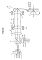
FIG. 11 shows an example of the optical pickup
apparatus in which spherical aberration detecting means
50 is added between the coupling lens system 3 and the
actuator 4 of the optical system 1b shown in FIG. 10.
The spherical aberration detecting means 50 comprised a
beam splitter 6, a lens 7, a hologram 8, a light-receiving
element 9, etc. It should be noted that the
hologram 8 has two different diffraction areas 8a and 8b,
and the light-receiving element 9 has two light-receiving
elements 9a and 9b. Other structures are the
same as that shown in FIGS. 5A and 5B, and descriptions
thereof will be omitted.
In this example, a part of the light beam
reflected by the optical information recording medium 5
is reflected by the beam splitter 6, and is converged by
the lens 7. The converged light beam is diffracted by
the diffraction areas 8a and 8b toward the light-receiving
elements 9a and 9b, respectively. Thus, an
amount and a direction of the spherical aberration of
the light reflected by the optical information recording
medium 5 cab be detected by comparing amounts of light
received by the light-receiving elements 9a and the
light-receiving element 9b with each other. It should
be noted that if there is a color aberration, the color
aberration can also be detected by the same detecting
means.
Therefore, according to the spherical
aberration detecting means 50, a spherical aberration or
a color aberration can be prevented from being generated
in the disc surface spot by causing the detection signal
to be zero by moving the first coupling lens 31 or the
second coupling lens 32 of the coupling lens system 3.
That is, the optical pickup apparatus is
provided with the spherical aberration detecting means
50 that corresponds to at least one of the laser light
sources 11L and 12L.
In the meantime, a semiconductor laser as a
laser light source has a characteristic in that a
wavelength changes immediately as an output power
changes. Accordingly, a chromatic aberration is
generated due to the slight difference in wavelength
between reproduction time and recording time. Since
this chromatic aberration is generated rapidly, there
may be a time lag if it is corrected by moving a
coupling lens system, which causes an error in
reproduction or recording.
In order to solve this problem, it is
effective to use an achromatic lens as the coupling lens.
Specifically, as shown in FIG. 12, a laminated lens is
used as a first coupling lens 31', which is a fixed side
of the coupling lens system 3. That is, the first
coupling lens 31' of the coupling lens system 3 is an
achromatic lens, which corrects the chromatic aberration
of the spot formed by converging a light beam from at
least one of the laser light sources 11L and 12L on the
recording surface of the optical information recording
medium 5.
It should be noted that the number of the
laser light sources in the optical system of the optical
pickup apparatus of the present invention is not limited
to two.
Thereby, a chromatic aberration can be
eliminated without increasing the weight of the driving
part. It should be noted that structures other than the
first coupling lens 31' of the coupling lens system 3
are the same as that shown in FIGS. 5A and 5B, and
descriptions thereof will be omitted.
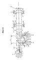
As shown in FIG. 13, when using three hologram
units 11, i.e., the first hologram unit 11, the second
hologram unit 12 and a third hologram unit 13, the
travel distance of the second coupling lens 32 may
become excessively large. In such a case, a fixed lens
11S may be provided to the laser light source 11L so as
to reduce the travel distance of the second coupling
lens 32. That is, fixed lens 11S, which changes a
degree of divergence of the light beam from the laser
light source 11L, is provided in an optical path between
at least one of the three laser light sources 11L, 12L,
13L and the coupling lens system (coupling lens) 3.
It should be noted that the laser light source
to which the fixed lens 11S is provided is not limited
to the laser light source 11L. Moreover, the number of
the hologram units is not limited to three. Other
structures shown in FIG. 13 are the same as that shown
in FIGS. 5A and 5B, and descriptions thereof will be
omitted.
As appreciated from the above description,
there is provided according to the present embodiment an
optical pickup apparatus, which can couple light beams
from a plurality of light sources with a simple
structure, and is capable of correcting a chromatic
aberration and a spherical aberration generated due to
fluctuation in wavelength, a multi-layer disc structure,
and a variation in thickness of a disc substrate.
It should be noted that the above-mentioned
optical pickup is preferably mounted in an optical disc
drive apparatus.
(Second Embodiment)
A description will now be given of a second
embodiment of the present invention. It should be noted
that parts that are equivalent to the parts described in
the above description are given the same reference
numerals, and descriptions there of may be omitted.
A light beam projected from a semiconductor
laser is a radially expanding light beam, and a beam
diameter parallel to the junction plane of the
semiconductor laser is different from a beam diameter of
perpendicular to the junction plane. For this reason,
in an optical pickup apparatus, generally, the beam
diameters in all directions are equalized by using a
beam shaping prism so as to equalize a rim intensity of
the light beam incident on an objective lens having a
circular aperture, thereby suppressing reduction in an
amount of light.
However, a beam shaping prism cannot be
provided in an optical system using a CL expander since
an optical path is a diverging/converging optical path.
For this reason, in order to perform beam shaping
plastic using in the optical system using the CL
expander, it is desirable to apply an optical system in
which a beam shaping lens is arranged between an light
source and a coupling lens capable of changing a
magnification.
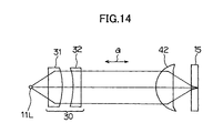
Thus, as shown in FIG. 14, a cupping lens
system 30 is constituted by a first coupling lens 31
that changes a diverging light beam projected from the
light source 11L into a light beam substantially
parallel to the optical axis and a second coupling lens
(first means) 32 that corrects a chromatic aberration of
the entire optical system, so as to reduce a chromatic
aberration of the optical system generated due to
wavelength fluctuation of the light source 11 by a
chromatic aberration correction of a diffracting part.
In the optical system, a spherical aberration generated
due to a variation in wavelength of the light source 11L
is reduced by setting by a second means a distance
between the light source 11L and a first surface on
which the light beam from the light source 11L is
incident.
Accordingly, an aberration due to wavelength
fluctuation is reduced by the second coupling lens
(diffraction surface: first means) provided in the
coupling lens system 30, and an aberration due to
wavelength variation is reduced by the second means
which adjusts the distance between the light source 11L
and the coupling lens system 30 in the direction "a" of
the optical axis within a wide range of a short
wavelength.
FIG. 15 is an illustration of an optical
system of an optical pickup apparatus according to a
second embodiment of the present invention. The optical
system 10A shown in FIG. 15 comprises a first hologram
unit 11, a first coupling lens (a group of lenses) 31, a
beam splitter (optical path synthesizing and separating
means) 20, a second coupling lens (a group of lenses) 32,
an aperture 241 and an objective lens 242 that are
arranged along a straight line in that order. The
optical system 10A also comprises a second hologram unit
12, which faces the beam splitter 2 and has an optical
axis perpendicular to the straight line.
It should be noted that the first coupling
lens system 30 includes the first coupling lens (a group
of lenses) 31, a second coupling lens (a group of
lenses) 32. Additionally the first coupling lens 31 is
provided with a single-axis actuator 33 for driving the
first coupling lens 31 in the direction "a" of the
optical axis, etc.
The objective lens 242 is moved by an actuator
243 in the direction "a" of the optical axis. Here,
although a dichroic prism utilizing a difference in
wavelength between the first hologram unit 11 and the
second hologram unit 12 is used as the beam splitter 20,
a polarizing prism may be used instead.
The first hologram unit 11 is provided with a
laser light source 11L, a hologram element 11h for
acquiring a necessary signal by diffracting a light
reflected by an optical information recording medium,
and a light-receiving element 11p for generating various
signals. In this example, the first hologram unit 11
performs recording and reproduction on a DVD (optical
information recording medium) 15a.
Similarly, the second hologram unit 12 is
provided with a laser light source 12L, a hologram
element 12h for acquiring a necessary signal by
diffracting a light reflected by an optical information
recording medium, and a light-receiving element 12p for
generating various signals. In this example, the second
hologram unit 12 performs recording and reproduction on
a CD (optical information recording medium) 15b.
That is, the optical recording apparatus
performs recording and reproduction on both the DVD 15a
and the CD 15b by converging the light beams from the
light sources 11L and 12L onto the DVD 15a and the CD
15b (both are optical information recording media),
respectively. The optical pickup apparatus comprises:
two light sources 11L and 12L corresponding to the DVD
15a and the CD 15b; the beam splitter (optical
synthesizing and separating means) 20 for synthesizing
and separating the light beams from the two light
sources 11L and 12L; at least one group of lenses (first
coupling lens 31) common to the light sources 11L and
12L; the coupling lens system (a coupling lens) 30
including a plurality of groups of lenses including the
first coupling lens 31 so as to converge the light beams
from the light sources 11L and 12L, the plurality of
groups of lenses constituting the coupling lens system
30 being located in the direction of the optical axis of
at least one light source 11L with the beam splitter
interposed therebetween; the objective lenses 242 that
converges the light beams passed through the coupling
lens system 30 onto the recording surfaces of the DVD
15a and the CD 15b corresponding to the light sources
11A and 12L, respectively; and the actuator (lens moving
means) 33 for moving at least the first coupling lens 31
from among the plurality of group of lenses in the
direction "a" of the optical axis. It should be noted
that the number of groups of lenses constituting the
coupling lens system 30 is not limited to two.
Moreover, the actuator (lens moving means) 33
is not limited to move the first coupling lens (one
group of lenses) 31, and may move the second coupling
lens (one group of lenses) 32. Further, the first
coupling lens (one group of lenses) 31 moved by the
actuator (lens moving means) in the direction "a" of the
optic axis may be arranged between the light source 11L
and the beam splitter (optical path synthesizing and
separating means) 20, or may be arranged between the
beam splitter (optical path synthesizing and separating
means) 20 and the objective lens 242.
In FIG. 15, a light beam emitted by the first
hologram unit 11 is indicated by solid lines, and a
light beam emitted by the second hologram unit 12 is
indicated by dotted lines.
In FIG. 15, the light beam from the first
hologram unit 11 transmits the first coupling lens 31,
which has been appropriately moved by the single-axis
actuator 33, and the beam splitter 20, and further
transmits the second coupling lens 32, which changes the
light beam into a parallel light. The parallel light
beam is then limited appropriately in its aperture
diameter by the aperture 41, and is converged onto the
recording surface of the DVD 15a by the objective lens
242. The light reflected by the DVD 15a is incident on
the first hologram unit 11 again after passing through
the objective lens 242, the second coupling lens 32, the
beam splitter 20 and the first coupling lens 31. The
light-receiving element 11p of the first hologram unit
11 generates a track signal, a focus signal, information
signal, etc., in accordance with the light received by
the light receiving unit 11p.
On the other hand, the light beam from the
second hologram unit 12 is reflected by the beam
splitter 20 and transmits the second coupling lens 32,
which changes the light beam into a parallel light. The
parallel light beam is then limited appropriately in its
aperture diameter by the aperture 41, and is converged
onto the recording surface of the CD 15b by the
objective lens 242. The light reflected by the CD 15b
is incident on the second hologram unit 12 again after
passing through the objective lens 242, the second
coupling lens 32 and the beam splitter 20. The light-receiving
element 12p of the second hologram unit 12
generates a track signal, a focus signal, information
signal, etc., in accordance with the light received by
the light receiving unit 12p.
It should be noted that, the objective lens
242 is servo-controlled by a two-axis actuator 243 in
accordance with the track signal and the focus signal so
s to always follow a movement of the disc so that a beam
spot of a diffraction limit is formed on the DVD 15a or
the CD 15b.
The parallel light from the coupling lens is
limited in its aperture to an aperture diameter
corresponding to NA0.65 for the DVD 15a and NA0.50 for
the CD 15b by the aperture (wavelength aperture limiting
element) 41.
The objective lens 242 is a DVD/CD compatible
diffraction lens, and each beam is converged onto a
recording surface of a disc having a substrate thickness
of 0.6 mm for the DVD 15a or a recording surface of a
disc having a substrate thickness of 1.2 mm for the CD
15b. The light reflected by the DVD 15a or the CD 15b
is incident on the hologram unit 11 or 12 again, and the
track signal, the focus signal, the information signal,
etc., are generated by the light-receiving element 11p
or 12p.
A description will be given of a coupling
efficiency of light beams.
From FIG. 16A, if a light taking angle of
the diverging light which satisfies the aperture
diameter dvd of the objective lens 242 and an RIM
specification (a specification of a light intensity at
an aperture part when an intensity of light at the
optical axis is 100) for the DVD 15a is determined, a
focal distance fdvd of the coupling lens for the DVD 15a
is given by the following equation.
fdvd=dvd/ (2×sindvd)
Similarly, from FIG. 16B, a focal distance fcd
for the CD 15b is given by the following equation
fcd=cd/ (2×sincd)
The following Table 2 indicates specific examples for
the DVD and the CD.
| | DVD | CD |
| DIVERGING ANGLE OF LIGHT SOURCE (HALF VALUE) LD | 10° | 10° | ACTIVE LAYER PARALLEL DIRECTION IN SEMICONDUCTOR LASER |
| MINIMUM VALUE OF RIM | 30% | 15% |
| FOCAL DISTANCE OF OBJECTIVE LENS fol | 3mm | 3mm |
| NUMERICAL APERTURE (NA) | 0.65 | 0.50 |
| APERTURE DIAMETER Φdvd. Φcd | 3.9 | 3.0 | Φ=2 × fol × NA |
| LIGHT TAKING ANGLE dvd, cd | 6.6° | 8.3° |
The beam taking angles for the DVD and the
CD are given by the following equation according to a
general formula of a Gaussian distribution.
=[{ln(RIM)/ln0.5}×(LD/2)2]1/2
By substituting values for the light taking
angle and the aperture diameter for the DVD and CD
in the equation (1), fdvd=17.0 mm and fcd=10.4 mm are
obtained.
Therefore, in FIGS. 16A and 16B, an optimum
coupling optical system can be acquired by arranging the
coupling lens system 30 so that the focal distance
between the laser light source 12L and the second
coupling lens 32 is set to 10.4 mm and the synthesized
focal distance between the laser light source 11L, the
first coupling lens and the second coupling lens 32 is
set to 17 mm.
Here, the synthetic focal distance in two
lenses is given by the following equation.
1/f=1/f1+1/f2-d/ (f1×f2)
According to the above equation (7), it can be
appreciated that if f2=fcd=10.4 mm and d=6, f=fdvd=17 mm
is obtained near f1=-11.
Examples of the coupling lens designed
according to the above-mentioned equations are indicated
in the following Table 2 and Table 3.
With a practical thick lens, the synthetic
focal distance of f=17.0 mm was obtained by setting the
focal distances to f1=-9.08 mm and f2=10.4 mm. It
should be noted that, in these examples, the thickness
of the hologram substrate of each hologram unit is
neglected.
Additionally, in the Tables 2 and 3, an
aspherical surface 1: k=0, A4=-0.4378×10⁻⁴ A6=0.×10-4,
A8=-0.1247×10⁻⁴; and an aspherical surface 2: k=0, A4=-0.4029×10⁻³,
A6=0.7711×10⁻⁵ and A8=-0.1402×10⁻⁶.
The following equation (8) was used for the
design.
Z=ch2/ (1+{1-(1+k)c2h2}+A4h4+A6h6+A8h8+A10h10
where Z is a coordinate of a surface
configuration in an optical axis direction, c is an
inverse number (curvature) of a radius r of curvature of
a surface, h is a radius in a direction perpendicular to
an optical axis, k is a conic coefficient, and A4, A6,
A8 and A10 are aspheric surface coefficients.
| DVD | RADIUS OF CURVATURE | DISTANCE BETWEEN SURFACES | MATERIAL |
| 1 | - | 6.41 | AIR | LIGHT SOURCE 11L |
| 2 | -2.37 | 1.0 | BK7 | FIRST COUPLING LENS 31 |
| 3 | -5.51 | 1.0 | AIR | ASPHERICAL SURFACE 1 |
| 4 | - | 4.0 | BK7 | BEAM SPLITTER 20 |
| 5 | - | 1.0 | AIR |
| 6 | 31.28 | 1.5 | BK7 | SECOND COUPLING LENS 32 |
| 7 | -6.30 | - | AIR | ASPHERICAL SURFACE 2 |
| CD | RADIUS OF CURVATURE | DISTANCE BETWEEN SURFACES | MATERIAL |
| 1 | - | 4.91 | AIR | LIGHT SOURCE 12L |
| 2 | - | 4.0 | BK7 | BEAM SPLITTER 20 |
| 3 | - | 1.0 | AIR |
| 4 | 31.28 | 1.5 | BK7 | SECOND COUPLING LENS 32 |
| 5 | -6.30 | - | AIR | ASPHERICAL SURFACE 2 |
In the present embodiment, the actuator (lens
moving means) 33 is provided to the first coupling lens
31 so as to move the first coupling lens 31 in the
direction "a" of the optical axis. Thereby, it is
possible to correct a spherical aberration generated in
each optical surface (recording surface) of the DVD
(optical information recording medium) 15a with respect
to the light beam of the light source 11L.
However, when the actuator 33 is provided to
the first coupling lens 31, a spherical aberration
cannot be corrected with respect to the light source 12L.
When setting the wavelength of the light
source 11L to 405 nm and the wavelength of the light-source
12L to 660 nm and if polycarbonate is used as a
material of a substrate of the optical disc, refraction
indices n(405) and n(660) at the wavelengths are
n(405)=1.621 and n(660)=1.579. If the thickness of the
substrate of the optical disc varies by 70 µm, the
spherical aberrations Δw(405) and Δw(660) generated at
the wavelengths are Δw(405)=0.007λ and Δw(660)=0.004λ.
Accordingly, it is appreciated that a spherical
aberration Δw tends to be generated as the wavelength is
shorter.
ΔW = 1485 n2 - 18n3 (NA)4 t2
Other examples of design using the above-mentioned
equation (8) are shown in the following Table
4 and Table 5. It should be noted that a refraction
index and an Abbe number of a nitration material shown
in Table 7 are used.
| | RADIUS OF CURVATURE | THICKNESS | MATERIAL |
| OBJECT SURFACE | - | 0 |
| 1 | - | 1.5 |
| 2 | - | 1.5 | BK7_SCHOTT |
| 3 | - | 0.5 |
| 4 | - | 3.2 | TAF1_HOYA |
| 5 | - | 0.1 |
| 6 | -454.8985 | 2.0 | BK7_SCHOTT |
| 7 | -11.32789 | 1.9707 |
| 8 | - | 5.0 | BK7_SCHOTT |
| 9 | - | 0.5 |
| 10 | 64.48589 | 3.0 | BK7_SCHOTT |
| 11 | -9.95256 | 0 |
| APERTURE SURFACE | - | 0 |
| 13 | 2.01507 | 1.7 | 'vc' |
| 14 | -18.13584 | 1 |
| 15 | - | 0.64 | 'PC' |
| 16 | - | 0.64099 |
| IMAGE SURFACE | - | 0 |
| SURFACE | CONFIGURATION | KORENICH COEFFICIENT | FOURTH COEFFICIENT | SIXTH COEFFICIENT | EIGHTH COEFFICIENT | TENTH COEFFICIENT |
| 6 | ASPHERIC SURFACE | 0 | 8.18E-04 | -5.92E-05 | 7.88E-05 | -1.76E-05 |
| 7 | ASPHERIC SURFACE | 0 | 4.62E-04 | -1.38E-05 | 1.93E-05 | -2.68E-06 |
| 11 | ASPHERIC SURFACE | 0 | 9.5DE-05 | 7.21E-07 | 4.82E-09 | 2.37E-11 |
| 18 | ASPHERIC SURFACE | -0.674258 | 3.65E-03 | 4.10E-05 | 8.16E-05 | -4.45E-05 |
| 19 | ASPHERIC SURFACE | 69.056492 | 1.33E-02 | -4.11E-03 | 5.95E-04 | -2.01E-05 |
| GLASS MATERIAL | REFRACTION INDEX | ABBE NUMBER |
| BK7_SCHOTT | 1.5168 | 64.16641024 |
| TAF1_HOYA | 1.7725 | 49.62353044 |
| 'vc' | 1.606142 | 58.59557118 |
| 'PC | 1.584991 | 30.21771276 |
In the above, the first coupling lens 31
corresponds to surfaces 6-7 and the second coupling
lenses 32 corresponds to surfaces 10-11. Here, if the
thickness of the surface 15 increases and a spherical
aberration is generated, a wavefront aberration reducing
effect as shown in FIG. 17 can be obtained by moving the
first coupling lens 31 in the direction "a" of the
optical axis. It should be noted that the actuator 33
may be provided to the lens having a largest absolute
value of the focal distance from among the tow groups of
lenses (the first coupling lens 31 and the second
coupling lens 32) that constitute the coupling lens
system 30.
An amount of divergence with respect to an
amount of shift in the optical axis direction of a lens
decreases as an absolute value of a focal distance of
the lens to be moved increases. For this reason, in
order to relax the drive accuracy of the lens to the
spherical aberration correction with respect to the
light source 1, one of the first coupling lens 31 and
the second coupling lens 32 whichever having a longer
focal distance is moved.
An amount of divergence with respect to an
amount of movement in the optical axis direction of a
group of lenses decreases as an absolute value of a
focal distance of the lens to be moved increases.
That is, an amount of change in a spherical aberration
with respect to a drive error decreases as an absolute
value of a focal distance of the group of lenses to be
moved increases. For this reason, in order to relax the
drive accuracy of the group of lenses when correcting a
spherical aberration of the light source 11L, one of the
first coupling lens 31 and the second coupling lens 32
whichever having a longer focal distance is moved.
In the meantime, the lens located between the
light source 11L and the beam splitter 20 is not limited
to only the first coupling lens 31, and a plurality of
groups of lenses may be used.
Moreover, the optical information recording
medium such as the DVD 15a may have a plurality of
recording surfaces formed in a layer structure, and at
least one group of lenses of the coupling lens system 30
(the first coupling lens 31 or the second coupling lens
32) may be moved in the direction "a" of the optical
axis by the actuator (lens moving means) 33 so as to
converge the light beam with respect to each recording
surface.
With respect to the DVD, there is a
specification of double-layer recording surface, in
which a spherical aberration is generated since a
thickness of each layer varies. Although the spherical
aberration seldom causes a problem when reading data
from a ROM disc or the like, it may give a remarkable
degradation to a recording characteristic such as
erasure of adjacent marks when writing data on an R disc,
an RW disc or the like. Therefore, by correcting the
spherical aberration by changing a degree of divergence
of a light beam incident on an objective lens by moving
the coupling lens 31 in the optical axis direction in
accordance with each layer, the characteristic can be
improved for both recording and reproduction.
Further, the optical information recording
medium such as the DVD 15a or the CD 15b may have
optical transmission layers, and at lease one group of
lenses of the coupling lens system 30 (the first
coupling lens 31 or the second coupling lens 32) may be
moved by the actuator (lens moving means) 33 in
accordance with a variation in the thickness of each
optical transmission layer.
Although it seldom causes a problem in CD or
DVD, in the Blu-ray and the AOD disc of short wavelength,
a spherical aberration is generated in a disc surface
spot due to a manufacturing tolerance in a thickness of
a disc substrate, which may degrade the recording and
reproducing performance. In such a case, the spherical
aberration can be corrected by changing a degree of
divergence of a light beam incident on the objective
lens 242 by moving the first coupling lens 31 or the
second coupling lens 32 in the direction "a" of the
optical axis in accordance with variation in the
thickness of the substrate. An amount of movement of
the lens may be adjusted so as to, for example, maximize
amplitude of an RF signal.
Moreover, at lease one group of lenses of the
coupling lens system 30 (the first coupling lens 31 or
the second coupling lens 32) may be moved by the
actuator (lens moving means) 33 in the direction "a" of
the optical axis in accordance with a wavelength
fluctuation of the light sources 11L and 12L.
Further, in the Blue-ray or the AOD disc, with
a change in an ambient temperature or an output power,
the wavelength of the light sources 11L and 12L may
fluctuate and a chromatic aberration may be generated in
a disc surface spot, which may cause a degradation in
the recording and reproducing performance. In such a
case, the color aberration can be corrected by changing
a degree of divergence of a light beam incident on the
objective lens 242 by moving the first coupling lens 31
or the second coupling lens 32 in the direction "a" of
the optical axis in accordance with a wavelength
fluctuation. An amount of movement of the lens may be
adjusted so as to, for example, maximize amplitude of an
RF signal.
Moreover, with respect to at least the light
beam having a shortest wavelength, the coupling lens
system 30 and the objective lens 242 through which the
light beam passes may be an achromatic lens system. In
such a case, a color aberration can be eliminated even
when a wavelength is instantaneously changed such as in
a mode hop, which reduces an error in recording and
reproduction.
A wavelength of a semiconductor laser as a
light source changes instantaneously when an output
power thereof changes. Accordingly, the wavelength
changes slightly between a time of reproduction and a
time of recording, which may generate a chromatic
aberration. Since the chromatic aberration is generated
instantaneously, there is a time delay if a correction
is performed by moving the coupling lens, which may be a
cause of recording or reproducing error. Such a problem
is remarkable particularly in the Blue-ray and AOD
having a short wavelength. In order to solve this
problem, it is effective to use an achromatic lens
system. Using a laminated lens as the coupling lens 32
and using an achromatic diffraction lens as the
objective lens 242, a color aberration due to mode hop
can be eliminated in each lens system as shown in FIG.
17, which results in reduction of recording and
reproducing error.
Additionally, the entire system of the
coupling lens system 30 and the objective lens 242
through which a light beam passes may be an achromatic
lens system.
A diffraction lens has a disadvantage, as
compared to a refraction lens, that a transmittance is
low while an aberration correcting function is high. If
it is desired to make an optical system having a high
transmittance, a refraction lens is used for the
objective lens by making the DVD light beam of FIG. 17
as a diverging light. In such a case, in order to
correct a chromatic aberration of the objective lens, a
design is given to a coupling lens to have a chromatic
aberration for correction. That is, achromatize is
performed in a whole system of an optical system in
which a coupling lens and an objective lens are combined.
It should be noted that, as shown in FIG. 18,
a third coupling lens 34 may be provided between the
second hologram unit 12 and the beam splitter 20 so as
to change magnification of the light beam of the light
source 12L by the third coupling lens 34, and chromatic
aberration correcting means may be provided to the third
coupling lens (a group of lenses) 34 for correcting a
chromatic aberration of the second coupling lens and the
objective lens 242. In this case, with respect to the
light beam of the light source 12L, a coupling lens
system is constituted by the third coupling lens 34 and
the second coupling lens 32.
In this structure, the third coupling lens 34
has the chromatic aberration correcting function to
correct collectively the chromatic aberration of the
third coupling lens 34, the second coupling lens 32 and
the objective lens 242. The chromatic aberration
correcting function of the third coupling lens 34 is
realizable by any one of methods of a laminated lens in
which a plurality of lenses made of a glass material
having different refraction indices, a combination lens,
a diffraction lens having a surface provided with a
diffraction surface.
The third coupling lens 34 is designed so as
to satisfy the following conditions, where focal
distances of lens elements 1 to n of the third coupling
lens 34 are f31 to f3n, and partial dispersions are V31
to V3n.
In the meantime, according to the present
embodiment, as shown in FIG. 19, spherical aberration
detecting means 25 may be provided for detecting a
spherical aberration of a reflected light beam, which
projected from the light source 11L or 12L and converged
onto and reflected by a recording surface of the DVD
(optical information recording medium) 15a or the CD
(optical information recording medium) 15b.
The spherical aberration detecting means 25
comprise a beam splitter 26, a lens 27, a hologram 28,
the light-receiving element 29, etc. It should be noted
that the hologram 28 has two different diffraction areas
28a and 28b, and the light-receiving element 29 has two
light-receiving elements 29a and 29b. Other structures
are the same as that shown in FIG. 15, and descriptions
thereof will be omitted.
The light beam incident on the hologram 28 is
diffracted by the two different diffraction areas 28a
and 28b toward the light-receiving elements 29a and 29b,
respectively. Then, an amount and a direction of the
spherical aberration of the light reflected by the disc
can be detected by comparing amounts of light received
by the light-receiving elements 29a and 29b. When there
is a chromatic aberration, the chromatic aberration can
also be detected by the detecting means.
Therefore, by causing a detection signal to
become 0 by driving the coupling lens by the spherical
aberration detecting means 25, it is possible to prevent
generation of a spherical aberration or a chromatic
aberration in a beam spot on a disc surface.
Moreover, in the coupling lens system 30, the
first coupling lens (a group of lenses) located closest
to the light source 11L may be a convex lens. According
to such a structure, a diverging angle of a diverging
light beam from the light-source 11L can be enlarged so
as to increase an intensity of a rim of the light beam
(RIM) incident on the objective lens 242. If the RIM
becomes large, the diameter of a spot diameter on a disc
surface is decreased, which improves the recording and
reproducing performance.
In such a case, the wavelength λA, which is a
wavelength of the optical beam passing through the first
coupling lens (group of lenses) 31 which is a convex
lens, and a wavelength λB, which is a wavelength of the
light beam not transmitting the convex lens, are set so
that a relationship λA<λB is satisfied.
The wavelength is decreased in the order of CD,
DVD and Blue-ray, the recording density is increased
even if the difference in NA is considered, and it is
necessary to further reduce a spot diameter on a surface
of a disc. In such a case, when setting the wavelength
of the light source 11L, which is on the side of the
convex lens, shorter than the wavelength of the light
source 12L, the RIM is increased, which realizes further
reduction in the spot diameter on a surface of a disc.
On the other hand, the first coupling lens (a
group of lenses) 31 closest to the light source 11 or
the third coupling lens (a group of lenses) 34 closest
to the light source 12L may be a convex lens.
As shown in FIG. 20, in an optical system 10Aa
of the optical pickup apparatus having the first
hologram unit 11, the second hologram unit 12 and the
third hologram unit 13 that have different wavelengths
from each other, the diverging light beams from the
hologram units 11 and 12 are reflected by the beam
splitters (optical path synthesizing and separating
means) and transmit the second coupling lens 32 after
passing through the first coupling lens 31 and the third
coupling lens 34, respectively. In such a case, each of
the first coupling lens 31, the third coupling lens 34
and the second coupling lens 32 is a convex lens.
Similarly, the diverging light beam from the
third hologram unit 13 transmits the beam splitters 20
and 21 and the second coupling lens 32, and is changed
into a parallel light. A dichroic prism utilizing a
difference in wavelength between the three hologram
units 11, 12 and 13 is used for each of the bam
splitters 20 and 21.
For example, when the first hologram unit 11
is for DVD, the second hologram nit 12 is for CD and the
third hologram unit is for AOD, the light beam from the
coupling lens system 30 is limited in an aperture
diameter corresponding to NA0.65 for DVD, NA0.50 for CD
and NA0.65 for AOD by the aperture (wavelength aperture
limiting element) 41, and is incident on the objective
lens 242.
The objective lens 242 is a three-wavelength
compatible diffraction lens so as to converge each light
beam onto the recording surface of the DVD 15a having a
substrate thickness of 0.6 mm, the recording surface of
the CD 15b having a substrate thickness of 1.2 mm or the
recording surface of AOD 15c having a substrate
thickness of 0.6 mm. The light beam incident on the
objective lens 242 is a parallel light for DVD and AOD,
and is a diverging light for CD. The reflected light
from the discs are incident on the respective hologram
units 11, 12 and 13, and the light-receiving elements
11h, 12h and 13h generate a track signal, a focus signal,
an information signal, etc.
The objective lens 242 converges a light beam
to form a beam spot of a diffraction limit on the
recording surface of each disc with respect to each
wavelength by always following a movement of each disc
by being servo-controlled in accordance with the track
signal and the focus signal.
Since the optical path for coupling can be
shortened by using a convex lens for each of the first
coupling lens 31, the second coupling lens 32 and the
third coupling lens 34, there is an advantage that the
size of the optical pickup apparatus can be reduced.
In addition, the wavelength λA, which is a
wavelength of the optical beam passing through the first
coupling lens 31 or the coupling lens 34 (both are
convex lenses), and a wavelength λB, which is a
wavelength of the light beam not transmitting the first
coupling lens 31 or the third coupling lens 34, may be
set so that a relationship λA<λB is satisfied.
In such a case, the light sources 11L and 12L
is set to a wavelength longer than the wavelength of the
light source 13L, a smaller RIM can be coupled, which
increases a coupling efficiency and a disc surface power,
thereby achieving high speed recording.
Moreover, at least one group of lenses movable
by the lens moving means in the optical axis direction
may be located between the light source and the light
path synthesizing and separating means, or at least one
group of lenses movable by the lens moving means in the
optical axis direction may be located between the light
path synthesizing and separating means and the objective
lens.
Moreover, the optical pickup apparatus shown
in FIG. 20 comprises the first hologram unit 11, the
second hologram unit 12 and the third hologram unit 13
that correspond to the respective three optical
information recording media (DVD 15a, CD 15b and AOD
15c), and further comprises another beam splitter
(another optical path synthesizing and separating means)
21 in addition to the beam splitter between the third
hologram unit 13 and the second coupling lens 32. In
such a case, the third hologram unit 13, the beam
splitter 20, the beam splitter 21, the second coupling
lens 32, and the objective lens 42 are aligned along a
substantially straight line, and a first hologram unit
11 is positioned perpendicular to the optical axis of
the beam splitter 20 with the first coupling lens 31
therebetween, and a second hologram unit 12 is
positioned perpendicular to the optical axis of the beam
splitter 21 with the third coupling lens 34 therebetween.
Comparing FIG. 15 and FIG. 20, the first
coupling lens (a group of lenses) 31 of the coupling
lens system 30 driven by the actuator 33 in FIG. 15 is
located on the side of the light source 11L with respect
to the beam splitter (optical path synthesizing and
separating means) 20, while the second coupling lens (a
group of lenses) 32 of the coupling lens system 30
driven by the actuator 33 in FIG. 20 is located on the
side of the objective lens 242 with respect to the beam
splitters (optical path synthesizing and separating
means) 20 and 21.
In FIG. 15, there is no need to change the
coupled state of the second hologram unit 12 for CD due
to variation in normal substrate thickness or a
wavelength fluctuation, and only the light beam of the
first hologram unit 11 for DVD is changed by adjustment
by moving the position of the coupling lens system 30.
In such a case, the lens closer to the light source 11L
than the beam splitter 20, that is, the first coupling
lens 31 is moved so as to change only one light beam.
Also in FIG. 20, although there is no need to
change the coupling state of the hologram unit 12 for CD,
it is necessary to change a coupling state of each of
the light beam of the first hologram unit 11 for DVD and
the light beam of the third hologram unit 13 for AOD by
adjustment by moving the position of the coupling lens
32. In such a case, the driving mechanism can be shared
by DVD and AOD by driving the second coupling lens
located closer to the objective lens 242 than the beam
splitter 21.
In the case of CD, the second coupling lens 32
is returned always to a fixed position.
Additionally, in the above-mentioned
embodiment, as shown in FIG. 21, beam shaping means 35
may be provided between the light source 11 and the
first coupling lens (a group of lenses) 31, which is
closest to the light source 11L in the coupling lens
system 30.
The bean shaping means 35 corresponds to a
diffraction surface or an anamorphic lens having
different magnification in directions parallel and
perpendicular to an active layer of the semiconductor
laser of the light source 13L in a plane perpendicular
to the direction "a" of the optical axis. It is
desirable in the optical pickup, to set M×///⊥≒1.0
where // is a divergence angle in a direction parallel
to the active layer and theta ⊥ is a diverging angle in a
direction perpendicular to the active layer. M is
referred to as a shaping magnification. The beam
shaping means 35 is designed so as to satisfy the
following relationship, where f// is a divergence angle
in a direction parallel to the active layer and f⊥ is a
diverging angle in a direction perpendicular to the
active layer.
M=f///f⊥
An anamorphic lens (beam shaping means 35)
having different magnifications in the directions
parallel to and perpendicular to the active layer of the
semiconductor laser of the light source 11L. When a
light beam passes through the beam shaping means 35,
which is a lens having different magnifications in the
two directions parallel to and perpendicular to the
active layer, the diverging angle of the light beam is
changed, which shapes the light beam. That is, the
anamorphic lens as the beam shaping means 35 is capable
of converting an elliptic converging light into a
circular converging light, and, a light using efficiency
(coupling efficiency) in the optical pickup can be
increased. An anamorphic, aspheric equation is shown
below.
Moreover, optical disc discriminating means
(not shown in the figures) may be provided in the
optical pickup apparatus for discriminating a kind of
each of a plurality of optical information recording
media (DVD 15a, CD 15b, AOD 15c) such as shown in FIG.
20 so as to move at least one group of lenses from among
the first coupling lens 31, the second coupling lens 32
and the third coupling lens 34 that constitute the
coupling lens system 30 by the actuator (lens moving
means) 33 in the direction "a" of the optical axis in
accordance with kinds of the optical information
recording media.
In this structure, the optical disc
discriminating means for discriminating a kind of an
optical disc attached is provided in the optical pickup
apparatus. As shown in FIG. 22, the optical disc
discriminating means comprises a light-receiving element
and a signal operation circuit that perform a
discrimination based on a signal output by a signal
detecting system of the optical pickup apparatus. The
signal output from the optical disc discriminating means
is input to a controller of the lens moving means such
as the actuator 33, and the lens moving means is
controlled by a lens driving means driver.
Optical discs are different in their substrate
thickness and refraction index depending on kinds of the
optical discs. For this reason, a spherical aberration
may be generated for each optical disc.
In this structure a wavefront aberration of
the optical system can be reduced by changing the
position of the coupling lens system 30 in accordance
with information obtained from the optical disc
discriminating means.
Additionally, the coupling lens system 30 or
the objective lens 242 may be located at a position in
the direction "a" of the optical axis so that an
aspheric aberration generated in each optical surface is
minimized.
A general semiconductor laser has variation in
oscillation wavelength de to the manufacture variation
of an active layer structure. In this structure, as
shown in FIG. 15, the position of each lens in the
direction "a" of the optical axis is fixed in accordance
with the oscillation wavelength of the light source 11A
so that a spherical aberration generated in each optical
surface is minimized. When a spherical aberration of
the optical system changes, each lens is moved in the
direction "a" of the optical axis with respect to the
fixed position of the lens as a center.
Moreover, as shown in FIG. 20, if there are
three light sources and the light source 11L is selected,
the position of the coupling lens 32 in the direction
"a" of the optical axis is fixed in accordance with the
oscillation wavelength of the light source 11L so that a
spherical aberration generated in each optical surface
is minimized. When the spherical aberration of the
optical system of the light source 11L changes, the
coupling lens 32 is moved in the direction "a" of the
optical axis with respect to the fixed position of the
lens as a center. If the light source 12L is selected,
the position of the coupling lens 32 in the direction
"a" of the optical axis is fixed in accordance with the
oscillation wavelength of the light source 12L so that a
spherical aberration generated in each optical surface
is minimized. When the spherical aberration of the
optical system of the light source 12L changes, the
coupling lens 32 is moved in the direction "a"" of the
optical axis with respect to the fixed position of the
lens as a center.
If the oscillation wavelength shifts, a
refraction index changes due to a dispersion
characteristic of a material used for the lens, thereby
generating a spherical aberration. The spherical
aberration can be changed into an optimum wavefront
aberration by shifting the position of the lens in the
optical axis direction. Furthermore, when a spherical
aberration is generated in an optical surface of the
optical pickup, the spherical aberration can be changed
into an optimum wavefront aberration by further moving
the from the shifted position. Moreover, for example,
if the light source 11L is selected, the position of the
coupling lens 32 in the direction "a" of the optical
axis is fixed in accordance with the oscillation
wavelength of the light source 11L so that a spherical
aberration generated in each optical surface is
minimized. Thereby, the spherical aberration generated
due to variation in the oscillation wavelength of the
light source 11L can be reduced. If the light source
12L is selected, the position of the coupling lens 32 in
the direction "a" of the optical axis is fixed in
accordance with the oscillation wavelength of the light
source 12L so that a spherical aberration generated in
each optical surface is minimized. Thereby, the
spherical aberration generated due to variation in the
oscillation wavelength of the light source 12L can be
reduced.
As shown in FIG. 23, the optical pickup
apparatus according to the above-mentioned embodiment
may be mounted on an optical disc drive apparatus. A
semiconductor laser serving as a light source of an
optical pickup 245 is driven and controlled by a laser
driver/laser controller of the optical disc drive
apparatus.
A signal output from the light-receiving
element of the optical pickup 245 is sent to each
controller through a signal operation circuit 246. Fo
signal and Tr signal for enacting an objective lens are
converted into control signals of the objective lens by
an Fo controller 247a and a Tr controller 247b. Further,
through an ACT driver 248, the output signal from the
signal operation circuit is converted into control
signal by a lens moving means driver 249a so that lens
moving means is driven by the lens moving means driver
49b. The lens moving means controller 49a and the lens
moving means driver 49b are mounted in the optical disk
drive apparatus.
Thus, it becomes possible to reduce a
spherical aberration generated due to various causes.
As apparent from the above description, there
is provided according to the present embodiment an
optical pickup apparatus, which can couple light beams
from a plurality of light sources with a simple
structure, and is capable of correcting a chromatic
aberration and a spherical aberration generated due to
fluctuation in wavelength, a multi-layer disc structure,
and a variation in thickness of a disc substrate.
The present invention is not limited to the
specifically disclosed embodiments, and variations and
modifications may be made without departing from the
scope of the present invention.