EP1574763A1 - Ventil mit abgedichteter Welle und Verfahren zur Montage des Ventils - Google Patents
Ventil mit abgedichteter Welle und Verfahren zur Montage des Ventils Download PDFInfo
- Publication number
- EP1574763A1 EP1574763A1 EP05290438A EP05290438A EP1574763A1 EP 1574763 A1 EP1574763 A1 EP 1574763A1 EP 05290438 A EP05290438 A EP 05290438A EP 05290438 A EP05290438 A EP 05290438A EP 1574763 A1 EP1574763 A1 EP 1574763A1
- Authority
- EP
- European Patent Office
- Prior art keywords
- sleeve
- shutter
- shaft
- hub
- bore
- Prior art date
- Legal status (The legal status is an assumption and is not a legal conclusion. Google has not performed a legal analysis and makes no representation as to the accuracy of the status listed.)
- Granted
Links
Images


Classifications
-
- F—MECHANICAL ENGINEERING; LIGHTING; HEATING; WEAPONS; BLASTING
- F16—ENGINEERING ELEMENTS AND UNITS; GENERAL MEASURES FOR PRODUCING AND MAINTAINING EFFECTIVE FUNCTIONING OF MACHINES OR INSTALLATIONS; THERMAL INSULATION IN GENERAL
- F16K—VALVES; TAPS; COCKS; ACTUATING-FLOATS; DEVICES FOR VENTING OR AERATING
- F16K41/00—Spindle sealings
- F16K41/02—Spindle sealings with stuffing-box ; Sealing rings
- F16K41/04—Spindle sealings with stuffing-box ; Sealing rings with at least one ring of rubber or like material between spindle and housing
- F16K41/043—Spindle sealings with stuffing-box ; Sealing rings with at least one ring of rubber or like material between spindle and housing for spindles which only rotate, i.e. non-rising spindles
- F16K41/046—Spindle sealings with stuffing-box ; Sealing rings with at least one ring of rubber or like material between spindle and housing for spindles which only rotate, i.e. non-rising spindles for rotating valves
-
- F—MECHANICAL ENGINEERING; LIGHTING; HEATING; WEAPONS; BLASTING
- F16—ENGINEERING ELEMENTS AND UNITS; GENERAL MEASURES FOR PRODUCING AND MAINTAINING EFFECTIVE FUNCTIONING OF MACHINES OR INSTALLATIONS; THERMAL INSULATION IN GENERAL
- F16K—VALVES; TAPS; COCKS; ACTUATING-FLOATS; DEVICES FOR VENTING OR AERATING
- F16K1/00—Lift valves or globe valves, i.e. cut-off apparatus with closure members having at least a component of their opening and closing motion perpendicular to the closing faces
- F16K1/16—Lift valves or globe valves, i.e. cut-off apparatus with closure members having at least a component of their opening and closing motion perpendicular to the closing faces with pivoted closure-members
- F16K1/18—Lift valves or globe valves, i.e. cut-off apparatus with closure members having at least a component of their opening and closing motion perpendicular to the closing faces with pivoted closure-members with pivoted discs or flaps
- F16K1/22—Lift valves or globe valves, i.e. cut-off apparatus with closure members having at least a component of their opening and closing motion perpendicular to the closing faces with pivoted closure-members with pivoted discs or flaps with axis of rotation crossing the valve member, e.g. butterfly valves
- F16K1/226—Shaping or arrangements of the sealing
- F16K1/2268—Sealing means for the axis of rotation
Definitions
- the present invention relates to shut-off valves offset.
- an offset shutter valve the axis of rotation of the shutter disk-shaped is offset from the plane of the shutter and is parallel to this plane.
- the axis of rotation is also eccentric with respect to the axis of piping.
- the combination of offset and eccentricity reduces the friction between the seat (seal) and the sealing surface when opening and closing the faucet.
- the faucet thus retains its characteristics after a very large number of maneuvers, these characteristics remaining compliant with standards and specifications, the most demanding. It is why, we use a lot of offset butterfly valves in the field high pressure, as well as in the field of water (adduction).
- the shutter is rotated about a quarter of a turn by a which further ensures the function of supporting the shutter when the latter is closed.
- a axis that plays a role identical to that of the tree as a support for the shutter, but which is not leading.
- the word "tree” also includes the axis opposite to the tree itself.
- a serious disadvantage of these offset shutter valves is that the shaft is exposed to the liquid that passes through the tap, especially as the liquid is under high pressure.
- the treatment of water consists in treating discharges by mechanical filtration and cation rebalancing and, where appropriate, optionally, addition of basic or acidic additives. It can also be done in the supply of drinking water that pumping carried out not far from the edge of the sea bring in the channels of slightly salty water aggressive vis-à-vis metals.
- operators inject oxidants into the water in the form of ozone and / or bleach.
- the drinking water thus contains oxidants which, especially in countries where the temperature can reach 60 ° C under shelter, have a high activity and are the source of pitting corrosion on ferrous metals.
- the body and the shutter of the faucets can be coated with ebonite or thick paint but trees and bores correspondents are not protected, so that the specifications specify that the material of the shaft in contact with the fluid must meet a minimum value determined by a quantity called "puncture index". This puncture index depends on the percentage of chromium, the percentage of molybdenum and that of nitrogen contained in the material. To satisfy this condition, the choice of material for trees is reduced to steels austenitic stainless and austenitic-ferritic stainless steels still called duplexes.
- the former have weak mechanical characteristics and the average mechanical characteristics, if we compare them with those of martensitic or precipitation stainless steels, these two shades being widely used in butterfly-centered faucets where there is no contact between shaft / axis and product conveyed.
- the invention radically suppresses corrosion of the tree by sting.
- the invention therefore relates to a faucet comprising a body cylindrical tubular whose opening can be closed by a shutter in disc form integral in rotation with a shaft, extending in a manner offset from the plane of the shutter and parallel to this plane, by via a hub in one piece with the shutter, characterized in that what the outer surface of the section of the tree, extending between the body and the hub, is provided with a means of protection vis-à-vis the corrosion and it is provided a first seal between the body and the means of protection and a second seal between the shutter and the means of protection.
- the protective means is a sleeve surrounding a large part of the tree, that is to say all the part that is at the outside of the hub and which passes through the shaft passage in the body.
- the means of protection is a stretch surrounding the section of the tree, which therefore extends only to the stretch of the tree extending between the body and the hub. The room added to the traditional tap is thus small does not cost much.
- the sleeve comprises a peripheral groove of flexibility that allows him to follow the relative deformations under the effect of the pressure of the parts on which it is centered.
- This throat can also, by the possibility of moving with the help of a tool that it offers, to facilitate fitting the valve making it safer to put the sleeve in place.
- the sleeve may also include a peripheral groove between a first housing for the first upholstery and a second housing for the second garnish.
- the groove is closer to the second housing than the first housing and is intended to receive a elastic ring abutting the radially outermost part of the hub when the sleeve is in position. The elastic ring thus prevents the sleeve to fall back from the position in which it seals.
- the protection means is a surface coating of the section, in particular chromium plating. Way to protection can also be a reported fret on the section.
- the invention it is possible to constitute the stainless steel shaft martensitic and therefore give it a smaller diameter while having a good mechanical resistance, but without fear that it will break under the effect of pitting.
- the method of mounting a valve according to the invention consists to put on a sleeve provided with a first and a second toppings seal and an elastic ring in a bore on the face outside the hub of the shutter so that the elastic ring remains outside the bore on the outer face of the hub, to put the shutter in position in the body by introducing it while the disc is in front until the hole in the hub of the shutter is aligned with the passage tree in the body and to pass the tree in the tree passage and in the bore of the hub.
- this displacement can be performed using a tool engaged in the softening groove which also serves to ensure the final position of the sleeve.
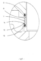
- Figure 1 is a sectional view of an offset butterfly valve according to the invention between two flanges of piping
- FIG. 2 is a view on a larger scale of part of the Figure 1 with enlarged view of the part surrounded by an oval, the right part of the figure representing the sleeve before it has reached its final position of mounting and the left part representing the sleeve in final position of mounting.
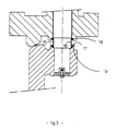
- Figures 3 and 4 are views similar to that of Figure 2 illustrating variants of the invention.
- Figure 5 shows on a larger scale the part surrounded by a oval of Figure 2.
- the tap shown in FIGS. 1 and 2 is the mode of preferred embodiment of many according to the invention.
- the shut-off valve staggered according to the invention is mounted in Figure 1 between two flanges of a piping.
- the valve essentially comprises a tubular body cylindrical and a disk-shaped shutter 2 mounted rotating relative to a shaft 3 offset from the plane of the shutter and parallel to this plane.
- An actuator 4 allows rotate the shaft 3.
- the shaft 3 is also off-center with respect to the axis of the piping that is to say the body.
- Shutter has one piece with the disc a hub 5 in which is formed a shaft passage.
- the outer surface of the section 3 extending between the body 1 and the hub 5 is provided with a sleeve 7 serving as a means of protection vis-à-vis the corrosion.
- the sleeve 7 of circular cross section is in one material resistant to pitting corrosion such as stainless steel austenitic or austenitic-ferritic stainless. It could also be in one plastic material, such as Teflon, resistant to pressure.
- the sleeve has a peripheral groove 8 decreasing the thickness, so that it can be better deformed under the action of pressure forces and follow a possible decentering of the shaft 3 with respect to the shutter 2.
- the thickness of the Sleeve at the bottom of the groove is 3 mm. In general, this thickness can be between 1 and 5 mm in general.
- Both ends of the sleeve 7 are provided two receiving housings of one first annular seal 9 and a second seal 10 annular sealing.
- the first seal 9 bears with a shoulder 11 of the body 1 and thus prevents the fluid go up along the shaft 3.
- the second seal 10 which as the first is performed in the form of an O-ring comes in contact with a circular bore 12 of the hub 5.
- a peripheral groove 13 in which is housed, when the sleeve 7 is in the mounted state as shown in the part left of Figure 2, an elastic ring 14 which acts as a stop on the face outermost point in the longitudinal direction of the axis of the bore 12. This ring 14 thus retains the sleeve 7.
- the second seal 10 prevents liquid from passing along the shaft 3 between the hub 5 of the shutter and the shaft 3.
- the section of the shaft lying between the body and the hub is surrounded by a ring 15 of corrosion-resistant steel. Both ends of the hoop, respectively applies an annular seal of section U-shaped cross section, one of the branches 16 of the U applying to the fret and the other branch 17 respectively applying to a shoulder 18 of the body and a bore 19 of the hub.
- the embodiment of Figure 4 more expensive but more simple to mount, includes a sleeve 20 extending over the entire passage shaft formed in the body and having two linings 21, 22 sealing respectively cooperating with the body and with the bore of the shutter hub. It is also planned, between the two fittings, a 23 softening throat.
Landscapes
- Engineering & Computer Science (AREA)
- General Engineering & Computer Science (AREA)
- Mechanical Engineering (AREA)
- Lift Valve (AREA)
- Hand Tools For Fitting Together And Separating, Or Other Hand Tools (AREA)
- Flanged Joints, Insulating Joints, And Other Joints (AREA)
- Joints With Pressure Members (AREA)
- Pens And Brushes (AREA)
- Sealing Battery Cases Or Jackets (AREA)
- Other Liquid Machine Or Engine Such As Wave Power Use (AREA)
- Details Of Valves (AREA)
- Replacement Of Web Rolls (AREA)
Applications Claiming Priority (2)
| Application Number | Priority Date | Filing Date | Title |
|---|---|---|---|
| FR0402526A FR2867544B1 (fr) | 2004-03-11 | 2004-03-11 | Robinet a arbre sec et son procede de montage |
| FR0402526 | 2004-03-11 |
Publications (2)
| Publication Number | Publication Date |
|---|---|
| EP1574763A1 true EP1574763A1 (de) | 2005-09-14 |
| EP1574763B1 EP1574763B1 (de) | 2006-11-08 |
Family
ID=34814569
Family Applications (1)
| Application Number | Title | Priority Date | Filing Date |
|---|---|---|---|
| EP05290438A Active EP1574763B1 (de) | 2004-03-11 | 2005-02-25 | Ventil mit abgedichteter Welle und Verfahren zur Montage des Ventils |
Country Status (5)
| Country | Link |
|---|---|
| EP (1) | EP1574763B1 (de) |
| AT (1) | ATE344895T1 (de) |
| DE (1) | DE602005000233T2 (de) |
| ES (1) | ES2275260T3 (de) |
| FR (1) | FR2867544B1 (de) |
Cited By (3)
| Publication number | Priority date | Publication date | Assignee | Title |
|---|---|---|---|---|
| DE102006002936A1 (de) * | 2006-01-21 | 2007-08-02 | Erhard Gmbh & Co. Kg | Armatur zum Absperren oder Regeln eines Mediums |
| US8291885B2 (en) | 2007-10-24 | 2012-10-23 | Continental Automotive Gmbh | Valve having a sleeve to prevent contamination and condensation |
| DE102014204396A1 (de) | 2014-03-11 | 2015-09-17 | Erhard Gmbh & Co. Kg | Absperrarmatur |
Citations (5)
| Publication number | Priority date | Publication date | Assignee | Title |
|---|---|---|---|---|
| US3967812A (en) * | 1975-02-26 | 1976-07-06 | Dresser Industries, Inc. | Shaft seal for corrosion resistant butterfly valve |
| DE2724007A1 (de) * | 1977-05-27 | 1978-12-07 | Wurzer Lothar | Absperr- oder rueckschlagklappe |
| US4294428A (en) * | 1977-04-01 | 1981-10-13 | Kubota, Ltd. | Butterfly valve |
| FR2731766A1 (fr) * | 1995-03-14 | 1996-09-20 | Ksb Ag | Dispositif de robinetteries |
| EP0905422A1 (de) * | 1997-04-14 | 1999-03-31 | Asahi Organic Chemicals Industry Co., Ltd. | Drehklappe |
-
2004
- 2004-03-11 FR FR0402526A patent/FR2867544B1/fr not_active Expired - Fee Related
-
2005
- 2005-02-25 AT AT05290438T patent/ATE344895T1/de not_active IP Right Cessation
- 2005-02-25 DE DE602005000233T patent/DE602005000233T2/de active Active
- 2005-02-25 ES ES05290438T patent/ES2275260T3/es active Active
- 2005-02-25 EP EP05290438A patent/EP1574763B1/de active Active
Patent Citations (5)
| Publication number | Priority date | Publication date | Assignee | Title |
|---|---|---|---|---|
| US3967812A (en) * | 1975-02-26 | 1976-07-06 | Dresser Industries, Inc. | Shaft seal for corrosion resistant butterfly valve |
| US4294428A (en) * | 1977-04-01 | 1981-10-13 | Kubota, Ltd. | Butterfly valve |
| DE2724007A1 (de) * | 1977-05-27 | 1978-12-07 | Wurzer Lothar | Absperr- oder rueckschlagklappe |
| FR2731766A1 (fr) * | 1995-03-14 | 1996-09-20 | Ksb Ag | Dispositif de robinetteries |
| EP0905422A1 (de) * | 1997-04-14 | 1999-03-31 | Asahi Organic Chemicals Industry Co., Ltd. | Drehklappe |
Cited By (4)
| Publication number | Priority date | Publication date | Assignee | Title |
|---|---|---|---|---|
| DE102006002936A1 (de) * | 2006-01-21 | 2007-08-02 | Erhard Gmbh & Co. Kg | Armatur zum Absperren oder Regeln eines Mediums |
| EP1811211A3 (de) * | 2006-01-21 | 2007-11-07 | Erhard GmbH & Co. KG | Armatur zum Absperren oder Regeln eines Mediums |
| US8291885B2 (en) | 2007-10-24 | 2012-10-23 | Continental Automotive Gmbh | Valve having a sleeve to prevent contamination and condensation |
| DE102014204396A1 (de) | 2014-03-11 | 2015-09-17 | Erhard Gmbh & Co. Kg | Absperrarmatur |
Also Published As
| Publication number | Publication date |
|---|---|
| ES2275260T3 (es) | 2007-06-01 |
| FR2867544B1 (fr) | 2007-11-09 |
| DE602005000233T2 (de) | 2007-08-23 |
| FR2867544A1 (fr) | 2005-09-16 |
| EP1574763B1 (de) | 2006-11-08 |
| DE602005000233D1 (de) | 2006-12-21 |
| ATE344895T1 (de) | 2006-11-15 |
Similar Documents
| Publication | Publication Date | Title |
|---|---|---|
| FR2642815A1 (fr) | Procede de fixation d'un tuyau souple a un raccord filete et raccordement de tuyau souple obtenu grace a ce procede | |
| EP0148807A1 (de) | Schutz für Rohrgewinde und Rohrverbindungskontaktflächen | |
| WO1984004069A1 (fr) | Procede et dispositif d'assemblage de plusieurs organes, notamment d'organes de liaison pour raccords de fluide | |
| CA1222676A (fr) | Butee ajustable d'un alesage d'un dispositif | |
| EP1574763B1 (de) | Ventil mit abgedichteter Welle und Verfahren zur Montage des Ventils | |
| US20080012300A1 (en) | Iron fitting for stainless steel tubing | |
| WO2011151533A1 (fr) | Robinet a joint d'etancheite en deux pieces | |
| FR2882585A1 (fr) | Robinet a siege a levres | |
| EP1055080B1 (de) | Vorrichtung und verfahren zum montieren eines sattels auf einer druckrohrleitung und dafür geeignetes ventil | |
| FR2887952A1 (fr) | Dispositif d'actionnement d'un robinet d'arret | |
| FR2798979A1 (fr) | Procede et dispositif pour raccordement mecanique etanche | |
| FR2487472A1 (fr) | Valve perfectionnee pour un robinet | |
| FR2644872A1 (fr) | Raccord coude orientable, a vis, pour tuyaux | |
| FR2882586A1 (fr) | Robinet a papillon a compression maitrisee du siege | |
| EP0058608A1 (de) | Kupplungsvorrichtung für Kanalisationen, Rohre und Leitungen sowie Verfahren zum Herstellen dieser Vorrichtung | |
| FR2690498A1 (fr) | Elément d'obturation pour boucher des orifices de passage de fluide de pression. | |
| JP2011007313A (ja) | バタフライ弁 | |
| EP1605195B1 (de) | Rohrkupplungssystem und dazu gehöriges Montageverfahren | |
| US20090173400A1 (en) | Combination sampling and pressure relief valve | |
| EP0821190A1 (de) | Metalldichtung, insbesondere für Armaturvorrichtung | |
| FR2620785A1 (fr) | Organe de controle de l'ecoulement d'un fluide constituant au moins un clapet anti-retour | |
| FR2504258A1 (fr) | Voyant pour canalisations | |
| FR2680857A1 (fr) | Procede et dispositif pour monter une vanne de commande dans une conduite de raccordement. | |
| FR2649464A1 (fr) | Robinet a boisseau | |
| FR2954448A1 (fr) | Electrovanne et installations d'assistance de conduite equipees d'une telle electrovanne |
Legal Events
| Date | Code | Title | Description |
|---|---|---|---|
| PUAI | Public reference made under article 153(3) epc to a published international application that has entered the european phase |
Free format text: ORIGINAL CODE: 0009012 |
|
| AK | Designated contracting states |
Kind code of ref document: A1 Designated state(s): AT BE BG CH CY CZ DE DK EE ES FI FR GB GR HU IE IS IT LI LT LU MC NL PL PT RO SE SI SK TR |
|
| AX | Request for extension of the european patent |
Extension state: AL BA HR LV MK YU |
|
| GRAP | Despatch of communication of intention to grant a patent |
Free format text: ORIGINAL CODE: EPIDOSNIGR1 |
|
| 17P | Request for examination filed |
Effective date: 20060314 |
|
| AKX | Designation fees paid |
Designated state(s): AT BE BG CH CY CZ DE DK EE ES FI FR GB GR HU IE IS IT LI LT LU MC NL PL PT RO SE SI SK TR |
|
| AXX | Extension fees paid |
Extension state: HR Payment date: 20060314 |
|
| GRAS | Grant fee paid |
Free format text: ORIGINAL CODE: EPIDOSNIGR3 |
|
| GRAA | (expected) grant |
Free format text: ORIGINAL CODE: 0009210 |
|
| AK | Designated contracting states |
Kind code of ref document: B1 Designated state(s): AT BE BG CH CY CZ DE DK EE ES FI FR GB GR HU IE IS IT LI LT LU MC NL PL PT RO SE SI SK TR |
|
| AX | Request for extension of the european patent |
Extension state: HR |
|
| PG25 | Lapsed in a contracting state [announced via postgrant information from national office to epo] |
Ref country code: IT Free format text: LAPSE BECAUSE OF FAILURE TO SUBMIT A TRANSLATION OF THE DESCRIPTION OR TO PAY THE FEE WITHIN THE PRESCRIBED TIME-LIMIT;WARNING: LAPSES OF ITALIAN PATENTS WITH EFFECTIVE DATE BEFORE 2007 MAY HAVE OCCURRED AT ANY TIME BEFORE 2007. THE CORRECT EFFECTIVE DATE MAY BE DIFFERENT FROM THE ONE RECORDED. Effective date: 20061108 Ref country code: AT Free format text: LAPSE BECAUSE OF FAILURE TO SUBMIT A TRANSLATION OF THE DESCRIPTION OR TO PAY THE FEE WITHIN THE PRESCRIBED TIME-LIMIT Effective date: 20061108 Ref country code: CZ Free format text: LAPSE BECAUSE OF FAILURE TO SUBMIT A TRANSLATION OF THE DESCRIPTION OR TO PAY THE FEE WITHIN THE PRESCRIBED TIME-LIMIT Effective date: 20061108 Ref country code: RO Free format text: LAPSE BECAUSE OF FAILURE TO SUBMIT A TRANSLATION OF THE DESCRIPTION OR TO PAY THE FEE WITHIN THE PRESCRIBED TIME-LIMIT Effective date: 20061108 Ref country code: SK Free format text: LAPSE BECAUSE OF FAILURE TO SUBMIT A TRANSLATION OF THE DESCRIPTION OR TO PAY THE FEE WITHIN THE PRESCRIBED TIME-LIMIT Effective date: 20061108 Ref country code: PL Free format text: LAPSE BECAUSE OF FAILURE TO SUBMIT A TRANSLATION OF THE DESCRIPTION OR TO PAY THE FEE WITHIN THE PRESCRIBED TIME-LIMIT Effective date: 20061108 Ref country code: FI Free format text: LAPSE BECAUSE OF FAILURE TO SUBMIT A TRANSLATION OF THE DESCRIPTION OR TO PAY THE FEE WITHIN THE PRESCRIBED TIME-LIMIT Effective date: 20061108 Ref country code: SI Free format text: LAPSE BECAUSE OF FAILURE TO SUBMIT A TRANSLATION OF THE DESCRIPTION OR TO PAY THE FEE WITHIN THE PRESCRIBED TIME-LIMIT Effective date: 20061108 |
|
| REG | Reference to a national code |
Ref country code: GB Ref legal event code: FG4D Free format text: NOT ENGLISH |
|
| REG | Reference to a national code |
Ref country code: CH Ref legal event code: EP |
|
| REG | Reference to a national code |
Ref country code: IE Ref legal event code: FG4D Free format text: LANGUAGE OF EP DOCUMENT: FRENCH |
|
| REF | Corresponds to: |
Ref document number: 602005000233 Country of ref document: DE Date of ref document: 20061221 Kind code of ref document: P |
|
| PG25 | Lapsed in a contracting state [announced via postgrant information from national office to epo] |
Ref country code: BG Free format text: LAPSE BECAUSE OF FAILURE TO SUBMIT A TRANSLATION OF THE DESCRIPTION OR TO PAY THE FEE WITHIN THE PRESCRIBED TIME-LIMIT Effective date: 20070208 Ref country code: DK Free format text: LAPSE BECAUSE OF FAILURE TO SUBMIT A TRANSLATION OF THE DESCRIPTION OR TO PAY THE FEE WITHIN THE PRESCRIBED TIME-LIMIT Effective date: 20070208 Ref country code: SE Free format text: LAPSE BECAUSE OF FAILURE TO SUBMIT A TRANSLATION OF THE DESCRIPTION OR TO PAY THE FEE WITHIN THE PRESCRIBED TIME-LIMIT Effective date: 20070208 |
|
| GBT | Gb: translation of ep patent filed (gb section 77(6)(a)/1977) |
Effective date: 20070124 |
|
| PG25 | Lapsed in a contracting state [announced via postgrant information from national office to epo] |
Ref country code: MC Free format text: LAPSE BECAUSE OF NON-PAYMENT OF DUE FEES Effective date: 20070228 |
|
| PG25 | Lapsed in a contracting state [announced via postgrant information from national office to epo] |
Ref country code: IS Free format text: LAPSE BECAUSE OF FAILURE TO SUBMIT A TRANSLATION OF THE DESCRIPTION OR TO PAY THE FEE WITHIN THE PRESCRIBED TIME-LIMIT Effective date: 20070308 |
|
| PG25 | Lapsed in a contracting state [announced via postgrant information from national office to epo] |
Ref country code: PT Free format text: LAPSE BECAUSE OF FAILURE TO SUBMIT A TRANSLATION OF THE DESCRIPTION OR TO PAY THE FEE WITHIN THE PRESCRIBED TIME-LIMIT Effective date: 20070409 |
|
| REG | Reference to a national code |
Ref country code: ES Ref legal event code: FG2A Ref document number: 2275260 Country of ref document: ES Kind code of ref document: T3 |
|
| PLBE | No opposition filed within time limit |
Free format text: ORIGINAL CODE: 0009261 |
|
| STAA | Information on the status of an ep patent application or granted ep patent |
Free format text: STATUS: NO OPPOSITION FILED WITHIN TIME LIMIT |
|
| 26N | No opposition filed |
Effective date: 20070809 |
|
| PG25 | Lapsed in a contracting state [announced via postgrant information from national office to epo] |
Ref country code: GR Free format text: LAPSE BECAUSE OF FAILURE TO SUBMIT A TRANSLATION OF THE DESCRIPTION OR TO PAY THE FEE WITHIN THE PRESCRIBED TIME-LIMIT Effective date: 20070209 |
|
| PG25 | Lapsed in a contracting state [announced via postgrant information from national office to epo] |
Ref country code: LT Free format text: LAPSE BECAUSE OF FAILURE TO SUBMIT A TRANSLATION OF THE DESCRIPTION OR TO PAY THE FEE WITHIN THE PRESCRIBED TIME-LIMIT Effective date: 20061108 |
|
| PG25 | Lapsed in a contracting state [announced via postgrant information from national office to epo] |
Ref country code: EE Free format text: LAPSE BECAUSE OF FAILURE TO SUBMIT A TRANSLATION OF THE DESCRIPTION OR TO PAY THE FEE WITHIN THE PRESCRIBED TIME-LIMIT Effective date: 20061108 |
|
| PGRI | Patent reinstated in contracting state [announced from national office to epo] |
Ref country code: IT Effective date: 20090401 |
|
| PG25 | Lapsed in a contracting state [announced via postgrant information from national office to epo] |
Ref country code: CY Free format text: LAPSE BECAUSE OF FAILURE TO SUBMIT A TRANSLATION OF THE DESCRIPTION OR TO PAY THE FEE WITHIN THE PRESCRIBED TIME-LIMIT Effective date: 20061108 Ref country code: LU Free format text: LAPSE BECAUSE OF NON-PAYMENT OF DUE FEES Effective date: 20070225 |
|
| PG25 | Lapsed in a contracting state [announced via postgrant information from national office to epo] |
Ref country code: HU Free format text: LAPSE BECAUSE OF FAILURE TO SUBMIT A TRANSLATION OF THE DESCRIPTION OR TO PAY THE FEE WITHIN THE PRESCRIBED TIME-LIMIT Effective date: 20070509 |
|
| REG | Reference to a national code |
Ref country code: CH Ref legal event code: PL |
|
| PG25 | Lapsed in a contracting state [announced via postgrant information from national office to epo] |
Ref country code: LI Free format text: LAPSE BECAUSE OF NON-PAYMENT OF DUE FEES Effective date: 20090228 Ref country code: CH Free format text: LAPSE BECAUSE OF NON-PAYMENT OF DUE FEES Effective date: 20090228 |
|
| REG | Reference to a national code |
Ref country code: FR Ref legal event code: PLFP Year of fee payment: 12 |
|
| REG | Reference to a national code |
Ref country code: FR Ref legal event code: PLFP Year of fee payment: 13 |
|
| REG | Reference to a national code |
Ref country code: FR Ref legal event code: PLFP Year of fee payment: 14 |
|
| PGFP | Annual fee paid to national office [announced via postgrant information from national office to epo] |
Ref country code: DE Payment date: 20230309 Year of fee payment: 19 |
|
| PGFP | Annual fee paid to national office [announced via postgrant information from national office to epo] |
Ref country code: NL Payment date: 20230427 Year of fee payment: 19 |
|
| PGFP | Annual fee paid to national office [announced via postgrant information from national office to epo] |
Ref country code: IT Payment date: 20230428 Year of fee payment: 19 Ref country code: IE Payment date: 20230427 Year of fee payment: 19 Ref country code: FR Payment date: 20230427 Year of fee payment: 19 Ref country code: ES Payment date: 20230503 Year of fee payment: 19 |
|
| PGFP | Annual fee paid to national office [announced via postgrant information from national office to epo] |
Ref country code: TR Payment date: 20230427 Year of fee payment: 19 |
|
| PGFP | Annual fee paid to national office [announced via postgrant information from national office to epo] |
Ref country code: BE Payment date: 20230427 Year of fee payment: 19 |
|
| PGFP | Annual fee paid to national office [announced via postgrant information from national office to epo] |
Ref country code: GB Payment date: 20230427 Year of fee payment: 19 |