EP1574724A1 - Pneumatisches Mikroventil - Google Patents
Pneumatisches Mikroventil Download PDFInfo
- Publication number
- EP1574724A1 EP1574724A1 EP04005720A EP04005720A EP1574724A1 EP 1574724 A1 EP1574724 A1 EP 1574724A1 EP 04005720 A EP04005720 A EP 04005720A EP 04005720 A EP04005720 A EP 04005720A EP 1574724 A1 EP1574724 A1 EP 1574724A1
- Authority
- EP
- European Patent Office
- Prior art keywords
- valve
- surface coating
- microvalve
- valve member
- microvalve according
- Prior art date
- Legal status (The legal status is an assumption and is not a legal conclusion. Google has not performed a legal analysis and makes no representation as to the accuracy of the status listed.)
- Granted
Links
- 238000000576 coating method Methods 0.000 claims abstract description 61
- 239000011248 coating agent Substances 0.000 claims abstract description 55
- 239000003921 oil Substances 0.000 claims description 37
- 238000005240 physical vapour deposition Methods 0.000 claims description 5
- 239000000463 material Substances 0.000 claims description 4
- 238000000034 method Methods 0.000 claims description 4
- 238000005229 chemical vapour deposition Methods 0.000 claims description 3
- 150000002222 fluorine compounds Chemical class 0.000 claims description 3
- 238000006116 polymerization reaction Methods 0.000 claims description 3
- 229910052710 silicon Inorganic materials 0.000 claims description 3
- 239000010703 silicon Substances 0.000 claims description 3
- 239000000126 substance Substances 0.000 claims description 3
- 239000002184 metal Substances 0.000 claims description 2
- 229910052751 metal Inorganic materials 0.000 claims description 2
- 239000004033 plastic Substances 0.000 claims description 2
- 239000007788 liquid Substances 0.000 description 14
- 239000000654 additive Substances 0.000 description 3
- PXHVJJICTQNCMI-UHFFFAOYSA-N Nickel Chemical compound [Ni] PXHVJJICTQNCMI-UHFFFAOYSA-N 0.000 description 2
- VYPSYNLAJGMNEJ-UHFFFAOYSA-N Silicium dioxide Chemical compound O=[Si]=O VYPSYNLAJGMNEJ-UHFFFAOYSA-N 0.000 description 2
- XUIMIQQOPSSXEZ-UHFFFAOYSA-N Silicon Chemical compound [Si] XUIMIQQOPSSXEZ-UHFFFAOYSA-N 0.000 description 2
- 230000000694 effects Effects 0.000 description 2
- 229920002313 fluoropolymer Polymers 0.000 description 2
- 239000004811 fluoropolymer Substances 0.000 description 2
- 239000012528 membrane Substances 0.000 description 2
- 239000002904 solvent Substances 0.000 description 2
- 229910052581 Si3N4 Inorganic materials 0.000 description 1
- 229910004298 SiO 2 Inorganic materials 0.000 description 1
- 230000001419 dependent effect Effects 0.000 description 1
- 230000005520 electrodynamics Effects 0.000 description 1
- 238000005516 engineering process Methods 0.000 description 1
- 239000012530 fluid Substances 0.000 description 1
- 239000012535 impurity Substances 0.000 description 1
- 230000001050 lubricating effect Effects 0.000 description 1
- 230000007257 malfunction Effects 0.000 description 1
- 229910052759 nickel Inorganic materials 0.000 description 1
- 229920000058 polyacrylate Polymers 0.000 description 1
- 229920001296 polysiloxane Polymers 0.000 description 1
- 230000035945 sensitivity Effects 0.000 description 1
- 235000012239 silicon dioxide Nutrition 0.000 description 1
- 239000000377 silicon dioxide Substances 0.000 description 1
- HQVNEWCFYHHQES-UHFFFAOYSA-N silicon nitride Chemical compound N12[Si]34N5[Si]62N3[Si]51N64 HQVNEWCFYHHQES-UHFFFAOYSA-N 0.000 description 1
- 238000005507 spraying Methods 0.000 description 1
- XLYOFNOQVPJJNP-UHFFFAOYSA-N water Substances O XLYOFNOQVPJJNP-UHFFFAOYSA-N 0.000 description 1
Images


Classifications
-
- F—MECHANICAL ENGINEERING; LIGHTING; HEATING; WEAPONS; BLASTING
- F16—ENGINEERING ELEMENTS AND UNITS; GENERAL MEASURES FOR PRODUCING AND MAINTAINING EFFECTIVE FUNCTIONING OF MACHINES OR INSTALLATIONS; THERMAL INSULATION IN GENERAL
- F16K—VALVES; TAPS; COCKS; ACTUATING-FLOATS; DEVICES FOR VENTING OR AERATING
- F16K99/00—Subject matter not provided for in other groups of this subclass
- F16K99/0001—Microvalves
-
- F—MECHANICAL ENGINEERING; LIGHTING; HEATING; WEAPONS; BLASTING
- F15—FLUID-PRESSURE ACTUATORS; HYDRAULICS OR PNEUMATICS IN GENERAL
- F15C—FLUID-CIRCUIT ELEMENTS PREDOMINANTLY USED FOR COMPUTING OR CONTROL PURPOSES
- F15C5/00—Manufacture of fluid circuit elements; Manufacture of assemblages of such elements integrated circuits
-
- F—MECHANICAL ENGINEERING; LIGHTING; HEATING; WEAPONS; BLASTING
- F16—ENGINEERING ELEMENTS AND UNITS; GENERAL MEASURES FOR PRODUCING AND MAINTAINING EFFECTIVE FUNCTIONING OF MACHINES OR INSTALLATIONS; THERMAL INSULATION IN GENERAL
- F16K—VALVES; TAPS; COCKS; ACTUATING-FLOATS; DEVICES FOR VENTING OR AERATING
- F16K99/00—Subject matter not provided for in other groups of this subclass
- F16K99/0001—Microvalves
- F16K99/0003—Constructional types of microvalves; Details of the cutting-off member
- F16K99/0005—Lift valves
- F16K99/0007—Lift valves of cantilever type
-
- F—MECHANICAL ENGINEERING; LIGHTING; HEATING; WEAPONS; BLASTING
- F16—ENGINEERING ELEMENTS AND UNITS; GENERAL MEASURES FOR PRODUCING AND MAINTAINING EFFECTIVE FUNCTIONING OF MACHINES OR INSTALLATIONS; THERMAL INSULATION IN GENERAL
- F16K—VALVES; TAPS; COCKS; ACTUATING-FLOATS; DEVICES FOR VENTING OR AERATING
- F16K99/00—Subject matter not provided for in other groups of this subclass
- F16K99/0001—Microvalves
- F16K99/0034—Operating means specially adapted for microvalves
- F16K99/0042—Electric operating means therefor
- F16K99/0048—Electric operating means therefor using piezoelectric means
-
- F—MECHANICAL ENGINEERING; LIGHTING; HEATING; WEAPONS; BLASTING
- F16—ENGINEERING ELEMENTS AND UNITS; GENERAL MEASURES FOR PRODUCING AND MAINTAINING EFFECTIVE FUNCTIONING OF MACHINES OR INSTALLATIONS; THERMAL INSULATION IN GENERAL
- F16K—VALVES; TAPS; COCKS; ACTUATING-FLOATS; DEVICES FOR VENTING OR AERATING
- F16K99/00—Subject matter not provided for in other groups of this subclass
- F16K99/0001—Microvalves
- F16K99/0034—Operating means specially adapted for microvalves
- F16K99/0042—Electric operating means therefor
- F16K99/0051—Electric operating means therefor using electrostatic means
-
- F—MECHANICAL ENGINEERING; LIGHTING; HEATING; WEAPONS; BLASTING
- F16—ENGINEERING ELEMENTS AND UNITS; GENERAL MEASURES FOR PRODUCING AND MAINTAINING EFFECTIVE FUNCTIONING OF MACHINES OR INSTALLATIONS; THERMAL INSULATION IN GENERAL
- F16K—VALVES; TAPS; COCKS; ACTUATING-FLOATS; DEVICES FOR VENTING OR AERATING
- F16K99/00—Subject matter not provided for in other groups of this subclass
- F16K2099/0073—Fabrication methods specifically adapted for microvalves
-
- F—MECHANICAL ENGINEERING; LIGHTING; HEATING; WEAPONS; BLASTING
- F16—ENGINEERING ELEMENTS AND UNITS; GENERAL MEASURES FOR PRODUCING AND MAINTAINING EFFECTIVE FUNCTIONING OF MACHINES OR INSTALLATIONS; THERMAL INSULATION IN GENERAL
- F16K—VALVES; TAPS; COCKS; ACTUATING-FLOATS; DEVICES FOR VENTING OR AERATING
- F16K99/00—Subject matter not provided for in other groups of this subclass
- F16K2099/0073—Fabrication methods specifically adapted for microvalves
- F16K2099/008—Multi-layer fabrications
Definitions
- the present invention relates to a pneumatic microvalve with a valve member arrangement and a plurality of valve channels, via the compressed air flow into the valve chamber assembly and can flow out and of which at least one valve channel can be closed by the valve member assembly.
- the valve member assembly includes, for example, a sheet-like valve member, which is driven, for example, electrostatically or piezo-electrically.
- the valve member typically has a small operating stroke, such as 10 to 20 ⁇ m.
- the force of the drive is sufficient to close tightly with the valve member one or more valve channels.
- the compressed air is often contaminated or contains additives that are added, for example, for the purpose of lubricating the compressed air. It can then happen that the oil settles in the valve chamber, for example in a stop region of the valve member and / or on the valve member. Due to capillary forces, the valve member then adheres, for example, to an inner wall surface of the valve chamber. The driving force for the actuation of the valve member is then no longer sufficient to actuate the valve member. Furthermore, the problem arises that due to the oil located in the valve chamber, the valve member no longer tightly seals the valve channel or channels. There are unwanted leaks.
- the surface energy density is also called "specific surface energy" designated.
- the surface energy density the sometimes also referred to simply as surface energy is smaller in the surface coating as in oil contained in the compressed air or optionally other liquids.
- surface energy density also of Surface tension.
- the surface tension of oil depends on the quality of the oil and is for example fresh Oil 40 mN / m or 40 dynes / cm.
- the surface tension takes e.g. with the age of the oil and can, for example come in the range of about 25 to 20 mN / m.
- the surface energy density the surface coating according to the invention Accordingly, depends appropriately on the quality of the oil contained in the compressed air and is for example advantageously 25 mN / m.
- the surface energy density of the surface coating suitably smaller, for example 20 mN / m or preferably maximum 15 mN / m.
- a surface coating from a fluorine compound for example a fluoropolymer, a fluorochemical acrylate polymer or The like, whose surface energy density expediently is 10 to 14 mN / m.
- the invention is based on the idea, one or more Surfaces in the valve chamber assembly with a coating at which the oil is relatively poor or can not adhere
- the oil can be the corresponding surfaces essentially no longer wet, but forms Drops that are expelled from the microvalve again, for example, when the valve member is actuated.
- the microvalve works reliably. Unwanted capillary effects, in which the valve member on a surface within the Valve chamber adheres, do not occur or at least substantially reduced form.
- the forces of the drive for the Valve member such as an electrostatic or piezoelectric Drive, are sufficient for reliable operation of the valve member, as an actuation of the valve member Disabling or even preventing capillary forces not or significantly reduced effect.
- the surface coating according to the invention in Area of the valve chamber assembly also in other in the Compressed air possibly contained substances is advantageous For example, if in the compressed air silicone, water, organic or synthetic oils or the like are included.
- the surface coating according to the invention is expediently thin. Their thickness is advantageously only a few Nanometers.
- valve chamber assembly the one or more valve chambers contains, in total, in its interior with the surface coating be provided.
- valve members each in whole or in part with the surface coating according to the invention expediently are provided.
- the solvent evaporates, for example Hydrofluoroether, after applying the surface coating completely or partially.
- the solvent is when the microvalve goes into operation, expediently substantially evaporated.
- the microvalve according to the invention is a comparatively small assembly, expediently the microsystem technology.
- the valve member assembly that is, one or more valve members, for example, have a maximum actuation stroke of 20 ⁇ m, but for example, also designs with actuation strokes of 30 - 40 ⁇ m are possible. Conveniently, the actuating stroke is still smaller, for example, at most 15 .mu.m or advantageously at most 10 .mu.m .
- the valve member assembly serves to close off one or more valve channels through which compressed air can flow indirectly into the valve chamber (s) and / or out of this or these.
- the base material of the microvalve according to the invention is advantageously silicon, for example SiO 2 . But it is also possible that the microvalve wholly or partly made of plastic, metal or the like, for example made of nickel.
- a multi-layer structure has been found to be useful exposed, for example, an opening layer with one or more valve channels, a cover layer and one or more between the opening layer and the cover layer arranged control layers present may be that the valve member assembly, for example in Shape of leaf-like valve members, comprise or form.
- the drive of the valve member is suitably electrostatically, but also piezoelectric or electrodynamic Drive variants are quite possible.
- the drive is advantageously contained in the microvalve.
- the surface coating is expediently in places present, in which the gaps between the valve member assembly and inner surfaces of the valve chamber assembly are small.
- the surface coating on the Valve member assembly disposed where the valve member assembly comes in contact with the inner surfaces for example when closing the valve channels.
- those inner surfaces provided with the surface coating associated with the valve member assembly come in contact or a small distance to have this.
- surfaces are advantageous the valve chamber assembly coated, which has a stop form for the valve member assembly.
- one valve channel or several valve channels provided with the surface coating according to the invention.
- a surface area surrounding the valve channel (s) the valve chamber arrangement is advantageously equipped with the surface coating according to the invention.
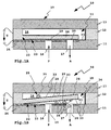
- the microvalve 10 shown in FIGS. 1A and 1B is in FIG realized a multi-layer structure, wherein the layers of the Micro valve 10 are suitably silicon layers, the by insulating layers, for example silicon dioxide or Silicon nitride, electrically isolated from each other. Consequently It is possible for one or more layers to be electrostatic Actuators or interacting with the actuators electrostatic Forming surfaces.
- the microvalve 10 serves e.g. to Actuation of a pneumatic consumer, not shown.
- the multilayer structure of the microvalve 10, a 2/2 valve is realized as follows: between an opening layer 11 and a cover layer 13, a control layer 12 is arranged.
- the layers 11-13 form a housing 37 and limit a valve chamber 14 of a valve chamber assembly 15 in Interior of the microvalve 10.
- valve channels 16, 17 can Compressed air flow into or out of the valve chamber 14, wherein the compressed air streams indicated by arrows P and A. are.
- the valve channels 16, 17 are closed.
- valve member 18 In its closed position, the valve member 18 closes openings 19, 20 of the valve channels 16, 17 on the lower inner surface the valve chamber 14.
- the e.g. plate-like valve member 18 lies on the inner surface 21 in its closed position on.
- the inner surface 21 forms a stop for the Valve member 18.
- valve member 18 In its open position, the valve member 18 from the openings 19, 20 lifted off. In this case, the valve member 18, the overall bendable and / or pivotable about an articulation region 23 is, from the openings 19, 20 and the valve channels 16, 17 away.
- the valve member 18 is for example by compressed air, the through the valve channel 16, e.g. the feed channel, into the valve chamber 14 flows in, pivoted away from the openings 19, 20 or bent away so that the compressed air in the valve chamber 14 can flow. Then there is a flow of compressed air from the valve channel 16 via the valve chamber 14 to the valve channel 17 possible.
- the microvalve 10 forms an integral drive 23, in the present case an electrostatic drive.
- the Drive 23 By pressing the Drive 23 is the valve member 18 in the closed position brought.
- the drive 23 is through the electrically conductive Valve member 18 and the control layer 12 and further by a electrically conductive conductive layer 24 at the top of Opening layer 11 and the underside of the valve chamber 24th realized.
- the drive 23 By applying a voltage U to the control layer 12 or the conductive layer 24, the drive 23 is actuated, wherein the valve member 18 into which the openings 19, 20th closing position is pivoted or bent.
- the microvalve 10 ' has similar components as the Microvalve 10, wherein the components of the microvalve 10 ' for better distinctness each with an additional attached 'are provided.
- the introduced into the valve chamber 14 'oil 25 has, for example a surface tension of about 20 to 40 mN / m on.
- the surface energy density of the surfaces in the valve chamber 14 ' that is, the corresponding inner surfaces of Layers 11'-13 'and the valve member 18' are greater than the surface tension of the oil 25. This has the consequence that the oil 25 wets the surfaces in the area of the valve chamber 14 '.
- lenses 26 ' form on the upper side the valve member 18 '. Except for the possibly unfavorable acting weight of the lenses 26 'on the valve member 18 'affect the lenses 26' the reliability of the microvalve 10 'still relatively little.
- surfaces having surface coatings which have a lower surface energy density than the oil 25, in this case for example a surface energy density of 10 to 15 mN / m or J / m 2, are present .
- the surface coatings contain, for example, fluorine compounds, for example fluoropolymers, or the like.
- the surface coatings are preferably produced by chemical and / or physical vapor deposition, but a plasma polymerization process is also possible.
- the valve chamber 14 is essentially, but not completely with an inventive Surface coating 33 provided.
- the lower and upper inner surface 21, 29 of the valve chamber 14 with the surface coating 33 which has a lower surface energy density has as the oil 25, provided.
- the top and bottom 28, 30 of the valve member 18 with the surface coating 33 coated are provided.
- a the free end of the valve member 18 opposite Side surface 34 of the valve chamber 14 is connected to the surface coating 33 provided. This measure prevents that is between the free end of the valve member 18 and the side surface 34 a liquid column in the manner of Fluid columns 31, 32 forms.
- the oil 25 may due to the surface coating 33 the do not wet coated surfaces of the valve chamber 14, as about the microvalve 10 ', but forms oil drops 35, the on the surface coating 33, so to speak.
- the oil 25 can be between the components in the area of the valve chamber 14 no or at least no significant liquid columns form. This causes capillary forces that may occur the driving force of the drive 23 exceed, not or at least only slightly.
- the oil drops 35 can by the effluent from the valve chamber 14 compressed air be conveyed out of the valve chamber 14. For example is located in Fig. 1B, an oil drop 35 on the Way out through the valve port 17 therethrough.
- valve chamber 14 also completely may be provided with the surface coating 33. It is but also possible that the surface coating 33 a smaller extent than in the embodiment according to Fig. 1A, 1B. For example, it would be possible only the surfaces the valve member 18, but not the inner surfaces of the Valve chamber 14 to be provided with the surface coating 33. But the reverse can also be the case. Further is a variant possible, in which essentially the articulation area 22 is provided with the surface coating 33, For example, surfaces that are located between the articulation area 22 and the valve channel 16 extend.
- valve channel 16 and / or the valve channel 17 with the surface coating to provide so that there the oil 25 can not adhere on the net.
- valve element arrangement coated according to the invention could be used also have a rigid valve plate, for example, by spring means with respect to the valve housing is suspended mobile.
- Microvalve 40 has a valve member assembly 41st bendable, plate-like valve members 42, 43.
- the valve members 42, 43 are formed by control layers 44, 45, between an upper and a lower cover layer 46, 47 are arranged. Located between the control layers 44, 45 an opening layer 48.
- the layers 44-48 form a housing 49 of the microvalve 40 and define valve chambers 50, 51 of a valve chamber assembly 52nd
- valve channel 55 in the opening layer 48 connects the upper with the lower valve chamber 50, 51st
- the electrostatically driven valve members 42, 43 are used for opening or closing the valve channel 55.
- the valve members 42, 43 are at the valve channels 53; 54 opposite Side of the housing 49 set.
- the valve members 42, 43 are bendable and / or pivotable flaps or membranes.
- the valve members 42, 43 are electrically conductive.
- valve member 42 By applying an actuation voltage U1 to the valve member 42 and to a conductive layer 56 at the top of the opening layer 58, the valve member 42 can be actuated so that Overall, an electrostatic drive is formed. In a corresponding manner, an operating voltage U2 to the Valve member 43 and to a conductive layer 57 at the top the lower cover layer 47 are applied to the valve member 43 to operate.
- valve members 42, 43 can be brought into the closed position, in the they close the valve channel 55. Then there is a flow interrupted by compressed air through the valve chamber assembly 52, that is, a flow path between the valve channels 53, 54 via the valve chamber assembly 52 is closed.
- this flow path is open, so that compressed air over flow the valve channel 53 into the valve chamber assembly 52 and via the valve channel 55 and the valve channel 53 from this can flow, for example, a not shown pneumatic actuator to operate.
- the compressed air may be contaminated, for example with oil 25.
- liquid column 58 forms between an upper side 58 of the Valve member 42 and the upper inner surface 62 of the valve chamber 50, a liquid column 58 from.
- the liquid column 58 of oil 25 pulls the valve member 42 so to speak upwards to the upper inner surface 62 of the valve chamber 50. This will an adjustment of the valve member 42 in the direction of the closed position difficult if not impossible.
- liquid columns 59, 60 are shown extending between the bottom 66 of the valve member 42 and the lower Inner surface 64 of the valve chamber 50 and the top of the Valve member 43 and the upper inner surface 63 of the valve chamber 51 extend. When operating the valve members 42, 43 must these liquid columns 59, 60 are displaced, which additional drive forces for driving the valve members 42, 43 is required.
- the microvalve 40 has a surface coating 61 which has a lower surface energy density than the oil 25, for example 12 to 18 J / m 2 .
- the surface coating 61 is provided in the region of the valve chamber assembly 52 at a plurality of surfaces in the region of the valve chamber assembly 52, for example at the upper inner surfaces 62, 63 and the lower inner surfaces 64, 65 of the valve chambers 50, 51.
- the surface coating 61 extends on the inner surfaces 62 and 65 into the valve channels 53, 54 into it.
- the lower surfaces 66, 67 of the valve members 42, 43 are provided with the surface coating 61.
- the surface coating 61 largely prevents liquid columns in the nature of the liquid columns 58, 60. Instead, oil droplets 68 are formed on the surfaces provided with the surface coating 61, which can be blown out of the valve chamber assembly 52 as shown, for example, in FIG. 4B.
Landscapes
- Engineering & Computer Science (AREA)
- General Engineering & Computer Science (AREA)
- Mechanical Engineering (AREA)
- Chemical & Material Sciences (AREA)
- Dispersion Chemistry (AREA)
- Computer Hardware Design (AREA)
- Microelectronics & Electronic Packaging (AREA)
- Theoretical Computer Science (AREA)
- Physics & Mathematics (AREA)
- Fluid Mechanics (AREA)
- Electrically Driven Valve-Operating Means (AREA)
Abstract
Description
Claims (15)
- Pneumatisches Mikroventil mit einer Ventilkammeranordnung (15; 52) und mehreren Ventilkanälen (16, 17; 53-55), über die Druckluft in die Ventilkammeranordnung (15; 52) einströmen und ausströmen kann und von denen mindestens ein Ventilkanal (16, 17; 53-55) durch die Ventilgliedanordnung (18; 41) verschließbar ist, dadurch gekennzeichnet, dass im Bereich der Ventilkammeranordnung (15; 52) mindestens eine Oberfläche (28, 30, 21, 29) mit einer Oberflächenbeschichtung (33; 61) vorhanden ist, die eine kleinere Oberflächenenergiedichte als in der Druckluft enthaltenes Öl (25) aufweist.
- Mikroventil nach Anspruch 1, dadurch gekennzeichnet, dass die Ventilgliedanordnung (18; 41) zumindest teilweise mit der Oberflächenbeschichtung (33; 61) versehen ist.
- Mikroventil nach Anspruch 1 oder 2, dadurch gekennzeichnet, dass eine einem oder mehreren der Ventilkanäle (16, 17; 53-55) zugewandte Oberfläche (30) der Ventilgliedanordnung (18; 41) mit der Oberflächenbeschichtung (33; 61) versehen ist.
- Mikroventil nach einem der vorhergehenden Ansprüche, dadurch gekennzeichnet, dass ein Anlenkbereich (22) der Ventilgliedanordnung (18; 41) an einem Gehäuse (37; 49) des Mikroventils mit der Oberflächenbeschichtung (33; 61) versehen ist.
- Mikroventil nach einem der vorhergehenden Ansprüche, dadurch gekennzeichnet, dass eine Oberfläche der Ventilkammeranordnung (15; 52) mit der Oberflächenbeschichtung (33; 61) versehen ist, die einen Anschlag für die Ventilgliedanordnung (18; 41) bildet.
- Mikroventil nach einem der vorhergehenden Ansprüche, dadurch gekennzeichnet, dass ein mindestens einen der Ventilkanäle (16, 17; 53-55) umgebender Oberflächenbereich (21) der Ventilkammeranordnung (15; 52) und/oder mindestens ein Ventilkanal (16, 17; 53-55) zumindest teilweise mit der Oberflächenbeschichtung (33; 61) versehen ist.
- Mikroventil nach einem der vorhergehenden Ansprüche, dadurch gekennzeichnet, dass die Innenoberfläche der Ventilkammeranordnung (15; 52) ganz oder im Wesentlichen mit der Oberflächenbeschichtung (33; 61) versehen ist.
- Mikroventil nach einem der vorhergehenden Ansprüche, dadurch gekennzeichnet, dass sein Basismaterial Silizium und/oder Kunststoff und/oder Metall ist.
- Mikroventil nach einem der vorhergehenden Ansprüche, dadurch gekennzeichnet, dass die Ventilgliedanordnung (18; 41) elektrostatisch und/oder piezo-elektrisch und/oder elektrodynamisch antreibbar ist und insbesondere einen derartigen Antrieb (23) aufweist oder bildet.
- Mikroventil nach einem der vorhergehenden Ansprüche,
dadurch gekennzeichnet, dass die Oberflächenbeschichtung (33; 61) eine Oberflächenenergiedichte von maximal 25 mN/m aufweist. - Mikroventil nach einem der vorhergehenden Ansprüche,
dadurch gekennzeichnet, dass die Oberflächenbeschichtung (33; 61) ganz oder teilweise im Rahmen eines chemischen und/oder physikalischen Dampf-Beschichtungsverfahrens und/oder eines Plasmapolymerisationsverfahrens hergestellt ist. - Mikroventil nach einem der vorhergehenden Ansprüche,
dadurch gekennzeichnet, dass die Oberflächenbeschichtung (33; 61) als eine Lösung aufgesprüht ist. - Mikroventil nach einem der vorhergehenden Ansprüche,
dadurch gekennzeichnet, dass die Oberflächenbeschichtung (33; 61) eine Fluorverbindung enthält. - Mikroventil nach einem der vorhergehenden Ansprüche,
dadurch gekennzeichnet, dass die Ventilgliedanordnung (18; 41) einen Betätigungshub von maximal 20 µm aufweist. - Mikroventil nach einem der vorhergehenden Ansprüche,
dadurch gekennzeichnet, dass es einen Mehrschichtaufbau mit insbesondere einer die mindestens zwei Ventilkanäle (16, 17; 53-55) enthaltenden Öffnungsschicht, einer Deckschicht und mindestens einer zwischen der Öffnungsschicht und der Deckschicht angeordneten, die Ventilgliedanordnung (18; 41) enthaltende Steuerschicht aufweist.
Priority Applications (2)
| Application Number | Priority Date | Filing Date | Title |
|---|---|---|---|
| DE200450006313 DE502004006313D1 (de) | 2004-03-10 | 2004-03-10 | Pneumatisches Mikroventil |
| EP20040005720 EP1574724B1 (de) | 2004-03-10 | 2004-03-10 | Pneumatisches Mikroventil |
Applications Claiming Priority (1)
| Application Number | Priority Date | Filing Date | Title |
|---|---|---|---|
| EP20040005720 EP1574724B1 (de) | 2004-03-10 | 2004-03-10 | Pneumatisches Mikroventil |
Publications (2)
| Publication Number | Publication Date |
|---|---|
| EP1574724A1 true EP1574724A1 (de) | 2005-09-14 |
| EP1574724B1 EP1574724B1 (de) | 2008-02-27 |
Family
ID=34814288
Family Applications (1)
| Application Number | Title | Priority Date | Filing Date |
|---|---|---|---|
| EP20040005720 Expired - Lifetime EP1574724B1 (de) | 2004-03-10 | 2004-03-10 | Pneumatisches Mikroventil |
Country Status (2)
| Country | Link |
|---|---|
| EP (1) | EP1574724B1 (de) |
| DE (1) | DE502004006313D1 (de) |
Cited By (3)
| Publication number | Priority date | Publication date | Assignee | Title |
|---|---|---|---|---|
| DE102017123672A1 (de) * | 2017-10-11 | 2019-04-11 | Samson Ag | Elektrostatisch-pneumatischer Umformer |
| CN109718875A (zh) * | 2018-12-24 | 2019-05-07 | 东南大学 | 一种基于pdms微流体结构上集成聚氨酯薄膜的方法 |
| CN114930058A (zh) * | 2019-11-01 | 2022-08-19 | 马修斯国际公司 | 包括喷注总成的非接触式沉积系统 |
Citations (7)
| Publication number | Priority date | Publication date | Assignee | Title |
|---|---|---|---|---|
| JPS5868562A (ja) * | 1981-10-15 | 1983-04-23 | Sanyo Electric Co Ltd | リ−ド弁 |
| US5622611A (en) * | 1996-05-22 | 1997-04-22 | Amtx, Inc. | Electroformed multilayer flow regulator incorporating force-generating means for selectively constricting the fluid flow path, and a process for the preparation thereof |
| EP0829649A2 (de) * | 1996-09-17 | 1998-03-18 | Fraunhofer-Gesellschaft Zur Förderung Der Angewandten Forschung E.V. | Mikroventil mit vorgespannter Ventilklappenstruktur |
| US6117396A (en) * | 1998-02-18 | 2000-09-12 | Orchid Biocomputer, Inc. | Device for delivering defined volumes |
| US6149123A (en) * | 1996-09-27 | 2000-11-21 | Redwood Microsystems, Inc. | Integrated electrically operable micro-valve |
| US20020117517A1 (en) * | 2000-11-16 | 2002-08-29 | Fluidigm Corporation | Microfluidic devices for introducing and dispensing fluids from microfluidic systems |
| US20020185184A1 (en) * | 2001-06-07 | 2002-12-12 | Nanostream, Inc. | Microfluidic synthesis devices and methods |
-
2004
- 2004-03-10 EP EP20040005720 patent/EP1574724B1/de not_active Expired - Lifetime
- 2004-03-10 DE DE200450006313 patent/DE502004006313D1/de not_active Expired - Fee Related
Patent Citations (7)
| Publication number | Priority date | Publication date | Assignee | Title |
|---|---|---|---|---|
| JPS5868562A (ja) * | 1981-10-15 | 1983-04-23 | Sanyo Electric Co Ltd | リ−ド弁 |
| US5622611A (en) * | 1996-05-22 | 1997-04-22 | Amtx, Inc. | Electroformed multilayer flow regulator incorporating force-generating means for selectively constricting the fluid flow path, and a process for the preparation thereof |
| EP0829649A2 (de) * | 1996-09-17 | 1998-03-18 | Fraunhofer-Gesellschaft Zur Förderung Der Angewandten Forschung E.V. | Mikroventil mit vorgespannter Ventilklappenstruktur |
| US6149123A (en) * | 1996-09-27 | 2000-11-21 | Redwood Microsystems, Inc. | Integrated electrically operable micro-valve |
| US6117396A (en) * | 1998-02-18 | 2000-09-12 | Orchid Biocomputer, Inc. | Device for delivering defined volumes |
| US20020117517A1 (en) * | 2000-11-16 | 2002-08-29 | Fluidigm Corporation | Microfluidic devices for introducing and dispensing fluids from microfluidic systems |
| US20020185184A1 (en) * | 2001-06-07 | 2002-12-12 | Nanostream, Inc. | Microfluidic synthesis devices and methods |
Non-Patent Citations (1)
| Title |
|---|
| PATENT ABSTRACTS OF JAPAN vol. 0071, no. 63 (M - 229) 16 July 1983 (1983-07-16) * |
Cited By (4)
| Publication number | Priority date | Publication date | Assignee | Title |
|---|---|---|---|---|
| DE102017123672A1 (de) * | 2017-10-11 | 2019-04-11 | Samson Ag | Elektrostatisch-pneumatischer Umformer |
| DE102017123672B4 (de) * | 2017-10-11 | 2026-01-08 | Samson Ag | Elektrostatisch-pneumatischer Umformer |
| CN109718875A (zh) * | 2018-12-24 | 2019-05-07 | 东南大学 | 一种基于pdms微流体结构上集成聚氨酯薄膜的方法 |
| CN114930058A (zh) * | 2019-11-01 | 2022-08-19 | 马修斯国际公司 | 包括喷注总成的非接触式沉积系统 |
Also Published As
| Publication number | Publication date |
|---|---|
| DE502004006313D1 (de) | 2008-04-10 |
| EP1574724B1 (de) | 2008-02-27 |
Similar Documents
| Publication | Publication Date | Title |
|---|---|---|
| EP0700485B1 (de) | Mikroventil | |
| DE19703415C2 (de) | Piezoelektrisch betätigtes Mikroventil | |
| DE69922288T2 (de) | Mikropumpe und Herstellungsverfahren für die Mikropumpe | |
| DE4422942B4 (de) | Vorrichtung für den Antrieb eines Mikroventils | |
| DE60204763T2 (de) | Mikropumpe | |
| EP2556282B1 (de) | Mikroventil mit elastisch verformbarer ventillippe, herstellungsverfahren und mikropumpe | |
| EP0478565A1 (de) | Mikroventil. | |
| EP1331538A1 (de) | Piezoelektrisch steuerbare Mikrofluidaktorik | |
| DE29708546U1 (de) | Elektrischer Festkörperaktuator mit hydraulischer Übersetzung | |
| DE60034465T2 (de) | Ein normalerweise geschlossenes einbaumikrorückschlagventil | |
| WO2018108576A1 (de) | Druckkopf zur applikation eines beschichtungsmittels | |
| WO2009065427A1 (de) | Pumpenanordnung mit sicherheitsventil | |
| DE102011005471A1 (de) | Mikro-Ejektor und Verfahren für dessen Herstellung | |
| EP1179139A1 (de) | Mikromechanische pumpe | |
| DE102011078770A1 (de) | Mikrofluidische Vorrichtung, mikrofluidisches System und Verfahren zum Transport von Fluiden | |
| DE102010061909A1 (de) | Fluidischer Aktor mit verformbarer Verschlussanordnung und langer Lagerfähigkeit | |
| WO1993010385A1 (de) | Mikromechanisches ventil für mikromechanische dosiereinrichtungen | |
| EP1576294A1 (de) | Normal doppelt geschlossenes mikroventil | |
| EP0829649B1 (de) | Mikroventil mit vorgespannter Ventilklappenstruktur | |
| EP1574724B1 (de) | Pneumatisches Mikroventil | |
| EP3687701A1 (de) | Applikator mit einem geringen düsenabstand | |
| EP1008765A2 (de) | Mikromechanische Aktorstruktur und Mikroventil | |
| DE102020002351B4 (de) | Druckkopf mit mikropneumatischer Steuereinheit | |
| DE602005002586T2 (de) | Hydraulische Betätigungseinrichtung | |
| DE102008054892A1 (de) | Vorhang-Auftragswerk |
Legal Events
| Date | Code | Title | Description |
|---|---|---|---|
| PUAI | Public reference made under article 153(3) epc to a published international application that has entered the european phase |
Free format text: ORIGINAL CODE: 0009012 |
|
| AK | Designated contracting states |
Kind code of ref document: A1 Designated state(s): AT BE BG CH CY CZ DE DK EE ES FI FR GB GR HU IE IT LI LU MC NL PL PT RO SE SI SK TR |
|
| AX | Request for extension of the european patent |
Extension state: AL LT LV MK |
|
| 17P | Request for examination filed |
Effective date: 20051224 |
|
| AKX | Designation fees paid |
Designated state(s): DE FR GB IT |
|
| 17Q | First examination report despatched |
Effective date: 20060921 |
|
| GRAP | Despatch of communication of intention to grant a patent |
Free format text: ORIGINAL CODE: EPIDOSNIGR1 |
|
| GRAS | Grant fee paid |
Free format text: ORIGINAL CODE: EPIDOSNIGR3 |
|
| GRAA | (expected) grant |
Free format text: ORIGINAL CODE: 0009210 |
|
| AK | Designated contracting states |
Kind code of ref document: B1 Designated state(s): DE FR GB IT |
|
| REG | Reference to a national code |
Ref country code: GB Ref legal event code: FG4D Free format text: NOT ENGLISH |
|
| REF | Corresponds to: |
Ref document number: 502004006313 Country of ref document: DE Date of ref document: 20080410 Kind code of ref document: P |
|
| GBT | Gb: translation of ep patent filed (gb section 77(6)(a)/1977) |
Effective date: 20080417 |
|
| PGFP | Annual fee paid to national office [announced via postgrant information from national office to epo] |
Ref country code: DE Payment date: 20080209 Year of fee payment: 5 |
|
| PGFP | Annual fee paid to national office [announced via postgrant information from national office to epo] |
Ref country code: IT Payment date: 20080327 Year of fee payment: 5 |
|
| ET | Fr: translation filed | ||
| PLBE | No opposition filed within time limit |
Free format text: ORIGINAL CODE: 0009261 |
|
| STAA | Information on the status of an ep patent application or granted ep patent |
Free format text: STATUS: NO OPPOSITION FILED WITHIN TIME LIMIT |
|
| 26N | No opposition filed |
Effective date: 20081128 |
|
| PGFP | Annual fee paid to national office [announced via postgrant information from national office to epo] |
Ref country code: GB Payment date: 20090220 Year of fee payment: 6 |
|
| PGFP | Annual fee paid to national office [announced via postgrant information from national office to epo] |
Ref country code: FR Payment date: 20090318 Year of fee payment: 6 |
|
| PG25 | Lapsed in a contracting state [announced via postgrant information from national office to epo] |
Ref country code: DE Free format text: LAPSE BECAUSE OF NON-PAYMENT OF DUE FEES Effective date: 20091001 |
|
| GBPC | Gb: european patent ceased through non-payment of renewal fee |
Effective date: 20100310 |
|
| REG | Reference to a national code |
Ref country code: FR Ref legal event code: ST Effective date: 20101130 |
|
| PG25 | Lapsed in a contracting state [announced via postgrant information from national office to epo] |
Ref country code: FR Free format text: LAPSE BECAUSE OF NON-PAYMENT OF DUE FEES Effective date: 20100331 |
|
| PG25 | Lapsed in a contracting state [announced via postgrant information from national office to epo] |
Ref country code: GB Free format text: LAPSE BECAUSE OF NON-PAYMENT OF DUE FEES Effective date: 20100310 Ref country code: IT Free format text: LAPSE BECAUSE OF NON-PAYMENT OF DUE FEES Effective date: 20090310 |