EP1574641A2 - Locking device for containers, doors, cabinets, furniture or the like. - Google Patents
Locking device for containers, doors, cabinets, furniture or the like. Download PDFInfo
- Publication number
- EP1574641A2 EP1574641A2 EP04029499A EP04029499A EP1574641A2 EP 1574641 A2 EP1574641 A2 EP 1574641A2 EP 04029499 A EP04029499 A EP 04029499A EP 04029499 A EP04029499 A EP 04029499A EP 1574641 A2 EP1574641 A2 EP 1574641A2
- Authority
- EP
- European Patent Office
- Prior art keywords
- lock
- locking
- locking device
- fixed part
- bolt
- Prior art date
- Legal status (The legal status is an assumption and is not a legal conclusion. Google has not performed a legal analysis and makes no representation as to the accuracy of the status listed.)
- Granted
Links
Images


Classifications
-
- E—FIXED CONSTRUCTIONS
- E05—LOCKS; KEYS; WINDOW OR DOOR FITTINGS; SAFES
- E05B—LOCKS; ACCESSORIES THEREFOR; HANDCUFFS
- E05B37/00—Permutation or combination locks; Puzzle locks
- E05B37/02—Permutation or combination locks; Puzzle locks with tumbler discs or rings arranged on a single axis, each disc being adjustable independently of the others
-
- E—FIXED CONSTRUCTIONS
- E05—LOCKS; KEYS; WINDOW OR DOOR FITTINGS; SAFES
- E05B—LOCKS; ACCESSORIES THEREFOR; HANDCUFFS
- E05B13/00—Devices preventing the key or the handle or both from being used
- E05B13/10—Devices preventing the key or the handle or both from being used formed by a lock arranged in the handle
- E05B13/103—Combination lock
-
- E—FIXED CONSTRUCTIONS
- E05—LOCKS; KEYS; WINDOW OR DOOR FITTINGS; SAFES
- E05B—LOCKS; ACCESSORIES THEREFOR; HANDCUFFS
- E05B13/00—Devices preventing the key or the handle or both from being used
- E05B13/10—Devices preventing the key or the handle or both from being used formed by a lock arranged in the handle
- E05B13/101—Devices preventing the key or the handle or both from being used formed by a lock arranged in the handle for disconnecting the handle
-
- E—FIXED CONSTRUCTIONS
- E05—LOCKS; KEYS; WINDOW OR DOOR FITTINGS; SAFES
- E05B—LOCKS; ACCESSORIES THEREFOR; HANDCUFFS
- E05B37/00—Permutation or combination locks; Puzzle locks
- E05B37/0031—Locks with both permutation and key actuation
-
- E—FIXED CONSTRUCTIONS
- E05—LOCKS; KEYS; WINDOW OR DOOR FITTINGS; SAFES
- E05B—LOCKS; ACCESSORIES THEREFOR; HANDCUFFS
- E05B37/00—Permutation or combination locks; Puzzle locks
- E05B37/0048—Permutation or combination locks; Puzzle locks with changeable combination
- E05B37/0058—Permutation or combination locks; Puzzle locks with changeable combination by axial disengagement between hub and rim of tumbler discs or rings
-
- E—FIXED CONSTRUCTIONS
- E05—LOCKS; KEYS; WINDOW OR DOOR FITTINGS; SAFES
- E05B—LOCKS; ACCESSORIES THEREFOR; HANDCUFFS
- E05B37/00—Permutation or combination locks; Puzzle locks
- E05B37/0075—Automatic scrambling
- E05B37/0079—Automatic scrambling when unlocking
Definitions
- the invention relates to a locking device for Containers, doors, cupboards, furniture or the like, with a Lock carrier, on which a combination lock is arranged, and a fixed part, in relation to which the lock carrier with the Combination lock is arranged rotatable.
- Known such locking devices usually have a closed and an open position, between which one Rotary handle or lock carrier of the closing device moves or can be rotated.
- the rotation of the lock carrier is usually by stop or limiting elements restricted, these stop and limiting elements often part of the locking or blocking serving Components of the locking device are or in the immediate technical-constructive connection to such Locking or blocking serving components are. at Twists of the locking device in the closed Condition can thus occur mechanical forces in the long term a reliable functioning of the locking device affected.
- the invention is based on the object, a locking device for containers, doors, cabinets, furniture or the like. of the at the outset described type such that mechanical Stresses on the components of the closing device be significantly reduced and that in particular the locking or Blocking serving components of the locking device to a much lesser extent than in the prior art or no longer mechanically stressed.
- the lock carrier with respect to the fixed part of a freewheel of 360 degrees.
- the lock carrier is in relation to the Fixed part freely rotatable in any way, being closed Condition of the locking device no stop or the like. takes place, by means of the rotational movement of the lock carrier in terms of the fixed part of the locking device in any Form would be restricted.
- Mechanical stresses of components of the locking device, in addition to this other components and the housing of the same belongs locked out. Any power transmission between the am Lock carrier arranged and with this freely rotatable combination lock and interlock actuatable by the combination lock or blocking elements of the closing device is at blocked or located in their closed position Locking device completely excluded.
- Locking device is provided with a secondary lock, arranged with the combination lock on the lock carrier is.
- the secondary lock can be used to lost key secret of the combination lock to find again, or the secondary lock can be a so-called.
- Lock with master key function by means of which the Locking device then spent in its open position can be when the key secret at the combination lock not set.
- Locking device has its combination lock a locking piece on, the key secret set at the combination lock in engagement with a locking latch device, on which a Closing member of the locking device is mounted and the in engaging with him locking piece with the Lock carrier is rotatable.
- the combination lock the Key secret is not set, exists at this Embodiment no interference between the numerical lock side Locking piece and the locking bolt of the locking device. Any mechanical stresses of the Locking bar or of associated with these components upon rotation of the lock carrier at the combination lock unlocked key secret thus reliably excluded. Only when the intervention between the numerical lock side Lock piece and the lock bolt made is, the locking bolt by rotation of the lock carrier be pressed, with the result that the locking device can be brought into its open position.
- the locking piece a nose the key secret set at the combination lock is pressed in the direction of the lock bolt and engages with a recess thereof when the Nose and the recess of the locking bolt are aligned.
- any mechanical stress also the locking piece or the nose of the same can be excluded, if between the Lock carrier and the fixed part of a positioning device is arranged by means of the lock carrier with respect to the fixed part or the locking bolt can be positioned in a rotational position is in which the locking piece and the locking bolt can be brought into engagement.
- the positioning device can be designed in terms of design less expensive way as a ball catch with a formed in the lock carrier or fixed part recess and one on the fixed part or on the lock carrier salaried ball form, wherein the ball by means of a biasing spring in Direction of the lock carrier or the fixed part biased is.
- the secondary lock can be used advantageously as a cylinder lock train, in which case the key of the cylinder lock quasi serve as a master key.
- the fixed part of the locking device according to the invention leaves expediently as simple on the container, on the door, on the cupboard, on the furniture or the like.
- attachable bottom plate form, with this sub-plate in a cylindrical Housing can be accommodated with the lock carrier is rotatable with respect to the lower plate.
- the locking device is advantageous provided with a sliding latch, by means of the secondary lock from his idle position to his operational position, in which it is the locking piece of the combination lock out of investment with Clutch discs of number wheels of the combination lock pushes, adjustable and by means of a spring in its rest position is biased.
- the locking device according to the invention with a sliding guide equipped on the inside of a cylindrical wall of the lower plate is formed and by means of the locking piece of the combination lock during rotation of the lock carrier with respect to the lower plate out of order with clutch discs of number wheels of the combination lock is depressible.
- the number wheels are on lifting the system between the locking piece on the one hand and the outer peripheral surfaces the clutch discs on the other hand by means of a multi-function spring provided spring arms adjusted, the Spring arms of the multifunction spring with with the clutch discs and interact with the numerical wheels connected actuators, which are shaped so that by means of the spring arms a rotation of the clutch discs and thus the number wheels takes place on an axis of the combination lock.
- a flap, a door, a Be communionniswandung or the like. can a right or a left turn of the locking bolt of the Closing device be appropriate.
- the Locking device according to the invention by means of a from behind Lockable slide with a control cam set, the with different arcuate Kulissenaus fundamentalesque in Lock bolt is engageable.
- a second positioning device is arranged by means of the locking bolt in his Closed position and in its right or left open position is positionable with respect to the lower plate.
- the locking device According to another advantageous inventive development with a Codierblech provided that to cancel the rotationally fixed engagement between the number wheels of the combination lock on the one hand and the clutch disks on the other hand axially displaceable is and in particular has a projection, with the lock open and the combination lock set key secret to the axial displacement of the Coding plate is actuated.
- the authorized user of Locking device knows the key secret of the combination lock, so that he, in case he changes the key secret wishes to open the locking device, wherein to set the key secret at the combination lock.
- the projection provided on the coding plate is actuated by means of a suitable tool.
- Displacement of the projection and thus the Codierblechs is the non-rotatable engagement between the number wheels and the Clutch discs of the combination lock lifted, so that the Rotational position of each number wheel with respect to its associated Clutch disc can be changed.
- Adjustment of the number wheels can return the coding plate in its assumed at the release of the projection axial position arrive, so that then the engagement between the Number wheels and the clutch discs restored becomes and the key secret of the combination lock accordingly the adjustment of the number wheels in relation to the clutch discs is changed.
- the Lock bolt between a blocked state on the hard part and a movable state to the fixed state is adjustable. If the locking bolt then blocked in his on the fixed part State is, it is not possible by means of a Bank card or the like. Through the door, flap, Torschlitz or the like. protrudes to the inside of the piece of furniture, the Lock bolt for the purpose of transferring the locking device in to move their opening position. An opening of the locking device in the manner indicated above is not then possible.
- the lock bolt at the combination lock key set secret from his at the festival part locked state in its movable to the fixed part Condition is adjustable. So if at the combination lock the currently valid key secret is set, the Lock bolt spent in its movable state to the fixed part.
- the key secret by means of the secondary castle To make it discoverable, it is expedient, if the locking bolt by means of the secondary lock from his am Fixed part blocked state in its movable to the fixed part Condition is adjustable.
- a blocking element provided arranged between the locking bolt and the fixed part is.
- the blocking element is expediently as a pressure bolt formed, which is guided in the lock bolt and with a Pin in a link device in a lock bolt protruding side of the fixed part protrudes.
- the link device advantageously has a holding position, in which the pin of the pressure bar is fixable.
- the fixed part side Sliding device a Freigabenut, in which the pin of the printing bolt with the key-lock set at the combination lock is adjustable.
- the festteil discoverede backdrop device has another release groove in the the pin of the pressure bolt by means of the secondary lock is adjustable.
- the locking device advantageously has a Slide spring on, by means of the pressure bolt from the first and / or the second release groove toward the Holding position is biased.
- a compression spring provided by means of the locking piece in a pin or the pressure bolt against the force of the slider spring the holding position in the first release groove adjusting direction is biased.
- a closure device 1 is used for example, a not shown in the figures Office or other piece of furniture, e.g. a control cabinet or the like., To close.
- the locking device 1 in the illustrated embodiment a combination lock 2, whose four number wheels 3 rotatable about an axis 4 of the combination lock 2 around are arranged.
- These number wheels 3 are not sitting directly on the axis 4, but between the number wheels 3 and the Axis 4 are coaxial with the axis 4 and with the number wheels 3 Clutch plates 5 are provided, one of which in each case a number wheel 3 is assigned.
- the clutch discs 5 have a larger diameter section in which Outer circumference a puncture 6 is formed. At the itself section adjacent to the large diameter section small diameter are on the outer peripheral surface engaging elements 7 arranged.
- the clutch plate side engagement elements 7 By axial displacement of the clutch plates 5 with respect to the number wheels 3 may be the clutch plate side engagement elements 7 in and out of engagement with the wheel side Recording elements 8 are provided. If the number wheels 3 with respect to the clutch discs 5 and thus in relation can be freely rotated on the axis 4, the key secret of the combination lock 2 can be set or changed. Once the engagement between the wheel-side receiving elements 8 and the clutch plate side engagement elements 7 then by a corresponding relative movement of the Clutch discs 5 is restored, is the new Key secret set on the combination lock 2.
- a Codierblech 9 For axial displacement of the clutch discs 5 is a Codierblech 9, which in the axial direction of the axis 4 slidably taken within a lock carrier 10 is.
- the coding plate 9 has, as is apparent from Figure 1, a down to box-shaped cross section, wherein in the Upper wall of the Codierblechs 9 recesses 11 are formed, through which the number wheels 3 protrude. Every recess 11 has its right in Figure 1 boundary wall Bridge 12 on, in the assembled state of the combination lock 2 each with a recess 6 of a clutch disc. 5 is engaged.
- the Codierblech 9 is in its longitudinal direction through the axis 4 penetrates, by means of known in the prior art Way the engagement between the clutch plates. 5 and the number wheels 3 can be canceled.
- the above-described combination lock 2 with the following to be described components is with a cylindrical Key lock trained secondary lock 13 on a provided with a cover plate 14 lock carrier 15 held.
- the combination lock 2 is with the lock carrier 15, the secondary lock 13 and one with the lock carrier 15th connected cylindrical housing 16 with respect to an inside this cylindrical housing 16 arranged sub-plate 17 rotatable, wherein the lower plate 17 with respect to the rest above-described components is arranged rotationally fixed.
- the combination lock 2 with the components forming it a total of the lower plate 17 rotatable, which in turn suitable manner on furniture or the like. is fixed.
- the coding plate 9 provided with a projection 18, which in with in their open position located closure device 1 actuated is.
- a multi-function spring 19 is arranged, by means of a above the multi-function spring 19th arranged within the lock carrier 10 locking piece 20 of the combination lock 2 in the direction of its release position is biased.
- the locking piece 20 is seated between the multi-function spring 19th and the Codierblech 9 and lies with its surface against the outer peripheral surfaces of the clutch plates 5 at. It can take his release position only if at the Number wheels 3 set key secret of combination lock 2 according to the clutch discs 5 with their flattened outer peripheral portions 21 facing the locking piece 20 are. Then the latter is the multifunctional spring 19 is pressed upward in Figure 1 direction.
- the locking bolt 24 extends through the lower plate 17 in the axial Direction and is at his the sub-plate 17 protruding End connected to a closing member 25, which by rotation of the locking bar 24 in and out of engagement with a in the latch not shown in the figures is adjustable.
- a positioning device is provided, by means of the lock carrier 15 in a rotational position with respect is positionable on the lower plate 17, in which the nose 22 of the locking piece 20 of the combination lock 2 with the recess 23 of the locking bar 24 is aligned.
- This positioning device is in the form of a ball catch configured and has a in the illustrated embodiment by means of a biasing spring 26 in the direction of the lower plate 17 preloaded ball 27, wherein the biasing spring 26th and the ball 27 in a receiving groove 28 of the lock carrier 15 are arranged.
- the ball 27 is associated with a recess 29 on the front side of a cylindrical wall 30 of the Lower plate 17.
- the ball 27 with the recess 29 in Alignment device it is slightly biased by the biasing spring 26 pressed into the recess 29, so that an exact Positioning of the lock carrier 15 with respect to the lower plate 17 is possible.
- the Lock carrier 15 can be the same positioning in Remove reference to the lower plate 17.
- a sliding latch 31st intended.
- the sliding bolt 31 has an approximately central recess 32, of a cylindrical projection 33 of the Locking bar 24 is penetrated.
- the shape of the recess 32 of the sliding latch 31 is selected so that the sliding latch 31 with respect to the cylindrical recess 33 of the locking bolt is movable back and forth.
- the sliding latch 31 has an operating portion 34 and diametrically opposite - a thumb 35. In his rest position is the parking lug 35 of the sliding latch 31, as can be seen in particular from FIG. 2 and FIG Section B - B of FIG. 17 shows, out of engagement with the nose 22 of the locking piece 20, against the clutch discs 5 of the out of the key secret disguised combination lock 2 is present. From its rest position, the sliding latch 31 in its operating position shown in Figure 6 and in Figure 13 adjustable by the secondary or cylinder lock 13 from its position shown in Figure 5 in his 9 is rotated in the position shown in FIG.
- spring arms can now with preferably trained as heart disks, with co-operate the actuating elements connected to the clutch disks, to the number wheels 3 of the combination lock 2 in the the Key secret of the combination lock 2 corresponding positions to twist.
- the nose 22 of the locking piece 20 by bevels 39th or 40 of the slotted guide 38 in Figure 25 and 1 upwards Direction moves so that the attachment between the locking piece 20 and the peripheral surfaces of the clutch discs 5 repealed is, with the result that on the multifunction spring 19 provided spring arms over with the clutch discs. 5 connected, preferably designed as heart discs actuators the clutch discs 5 and thus the number wheels 3rd from the set key secret of the combination lock 2 adjust.
- the latter has a slide 41, which can be actuated from the rear side of the closing device 1 and is restrained.
- the slider 41 has a control cam 42 and is in a provided in the lower plate guide groove 43rd guided.
- the control cam 42 of the slider 41 may in a a left turn or a clockwise rotation of the closing device 1 corresponding position spent, where each rotation of the closing device 1 each a Kulissenausnaturalung 44 and 45 is assigned in the lock latch 24.
- a further positioning device is provided, by means of the locking bolt 24 in defined Positions with respect to the lower plate 17 positionable is.
- This further positioning device also has one Spring 46 and a ball 47, by means of the spring 46 in Direction to the lower plate 17 is pressed. In the lower plate are in service and in the open position of the Locking bar 24 recesses 48 provided in the ball 47 engages by means of the spring 46 when the locking bolt 24 is in the position concerned.
- the closing device 1 When the closing device 1 is closed, it is the Combination lock 2 and the secondary lock 13 retaining lock carrier 15 with respect to the lower plate 17 and the means of another positioning device 46, 47, 48 on the lower plate 17 positioned locking latch 24 freely rotatable.
- the locking piece 20 When setting the key secret of the combination lock 2, the locking piece 20 is biased so that its nose 22nd upon rotation of the lock carrier 15 in the recess 23rd of the locking bar 24 engages, so that after this latching the locking bolt 24 is rotatable with the lock carrier 15 to the closing member 25 is not disengaged from that in figures to bring shown lock latch.
- first lock means 15 by means of the first positioning device 26, 27, 28, 29 to position so that already before the setting of the key secret the combination lock 2, the nose 22 of the locking piece 20 of the recess 23 of the locking bar 24 is opposite.
- any demands of Components of the locking device 1, the locking, Blocking or the like. serve, be excluded.
- Embodiment of the closing device according to the invention 1 differs from the one described above by a between the locking latch 24 on the one hand and the fixed part or the lower plate 17 on the other hand acting Blocking element in the form of a pressure bar 49.
- the pressure bar 49 has at its bottom in Figure 30 a pin 50, which projects into a link 51, which on the Pressure bar 49 facing side of the lower plate 17 is formed is.
- a holding position 52 a holding position 52, a first release groove 53 and a second release groove 54, wherein the first release groove 53 is radially inwardly of the second Release groove 54 is located and wherein in the radial direction between the two Freijuten 53, 54, the holding position 52 of the link device 51 is formed.
- the pressure bar 49 is displaceable in the radial direction in a Guide 57, which is formed in the locking bolt 24, held.
- a slider spring 55 which also in a corresponding recess of the Locking bar 24 is held and arranged and so is formed, that in the unloaded state of the slider spring 55 of the pressure bar 49 with its pin 50 in the Holding position 52 of the link 51 is located.
- This Position of the pressure bar 49 is a rotation between the locking latch 24 and the fixed part or the lower plate 17, the like with respect to a piece of furniture or the like. firmly arranged can not.
- the lock carrier 15, however, is after as before free with respect to the fixed part or the lower plate 17 rotatable.
- the locking latch 24 with respect to the fixed part or the lower plate 17, or the like on the piece of furniture. fixed is not to be turned.
- the figures 30 to 46 described embodiment of the locking device 1 is it thus also with unrestricted or not overlapping Doors, flaps or the like. of furniture not possible, that Closing member 25 of the locking device 1, the rotationally fixed on Locking latch 24 is seated, from its blocking in its release position to bring, even in case not because of that the unrestricted or non-overlapping design the doors, gates or the like. by means of a check card or the like. behind the door, the gate or the like can be penetrated.
Landscapes
- Lock And Its Accessories (AREA)
- Closures For Containers (AREA)
- Support Devices For Sliding Doors (AREA)
Abstract
Description
Die Erfindung bezieht sich auf eine Schließvorrichtung für Behältnisse, Türen, Schränke, Möbel od.dgl., mit einem Schlossträger, an dem ein Zahlenschloss angeordnet ist, und einem Festteil, in Bezug auf das der Schlossträger mit dem Zahlenschloss verdrehbar angeordnet ist.The invention relates to a locking device for Containers, doors, cupboards, furniture or the like, with a Lock carrier, on which a combination lock is arranged, and a fixed part, in relation to which the lock carrier with the Combination lock is arranged rotatable.
Bekannte derartige Schließvorrichtungen haben üblicherweise eine Geschlossen- und eine Offenstellung, zwischen denen ein Drehgriff bzw. Schlossträger der Schließvorrichtung bewegt bzw. gedreht werden kann. Die Verdrehung des Schlossträgers wird üblicherweise durch Anschlag- bzw. Begrenzungselemente eingeschränkt, wobei diese Anschlag- und Begrenzungselemente häufig Teil von der Verriegelung bzw. Blockierung dienenden Bauteilen der Schließvorrichtung sind oder doch in unmittelbarer technisch-konstruktiver Verbindung zu derartigen der Verriegelung bzw. Blockierung dienenden Bauteilen stehen. Bei Verdrehungen der Schließvorrichtung in deren geschlossenen Zustand können somit mechanische Kräfte auftreten, die langfristig eine zuverlässige Funktionsfähigkeit der Schließvorrichtung beeinträchtigten können. Known such locking devices usually have a closed and an open position, between which one Rotary handle or lock carrier of the closing device moves or can be rotated. The rotation of the lock carrier is usually by stop or limiting elements restricted, these stop and limiting elements often part of the locking or blocking serving Components of the locking device are or in the immediate technical-constructive connection to such Locking or blocking serving components are. at Twists of the locking device in the closed Condition can thus occur mechanical forces in the long term a reliable functioning of the locking device affected.
Der Erfindung liegt die Aufgabe zugrunde, eine Schließvorrichtung für Behältnisse, Türen, Schränke, Möbel od.dgl. der eingangs geschilderten Art derart weiterzubilden, dass mechanische Beanspruchungen der Bauteile der Schließvorrichtung erheblich reduziert werden und dass insbesondere der Verriegelung bzw. Blockierung dienende Bauteile der Schließvorrichtung in weitaus geringerem Maße als beim Stand der Technik bzw. gar nicht mehr mechanisch beansprucht werden.The invention is based on the object, a locking device for containers, doors, cabinets, furniture or the like. of the at the outset described type such that mechanical Stresses on the components of the closing device be significantly reduced and that in particular the locking or Blocking serving components of the locking device to a much lesser extent than in the prior art or no longer mechanically stressed.
Diese Aufgabe wird erfindungsgemäß dadurch gelöst, dass der Schlossträger in Bezug auf das Festteil einen Freilauf von 360 Grad aufweist. Der Schlossträger ist in Bezug auf das Festteil in beliebiger Weise frei drehbar, wobei in geschlossenem Zustand der Schließvorrichtung keinerlei Anschlag od.dgl. erfolgt, mittels der die Drehbewegung des Schlossträgers in Bezug auf das Festteil der Schließvorrichtung in irgendeiner Form eingeschränkt wäre. Mechanische Beanspruchungen von Bauteilen der Schließvorrichtung, wobei hierzu neben weiteren Bauteilen auch das Gehäuse derselben gehört, werden ausgeschlossen. Jedwede Kraftübertragung zwischen dem am Schlossträger angeordneten und mit diesem frei drehbaren Zahlenschloss und von dem Zahlenschloss betätigbaren Verriegelungs- bzw. Blockierelementen der Schließvorrichtung wird bei blockierter bzw. sich in ihrer Schließstellung befindlicher Schließvorrichtung vollständig ausgeschlossen.This object is achieved in that the Lock carrier with respect to the fixed part of a freewheel of 360 degrees. The lock carrier is in relation to the Fixed part freely rotatable in any way, being closed Condition of the locking device no stop or the like. takes place, by means of the rotational movement of the lock carrier in terms of the fixed part of the locking device in any Form would be restricted. Mechanical stresses of components of the locking device, in addition to this other components and the housing of the same belongs locked out. Any power transmission between the am Lock carrier arranged and with this freely rotatable combination lock and interlock actuatable by the combination lock or blocking elements of the closing device is at blocked or located in their closed position Locking device completely excluded.
Gemäß einer vorteilhaften Weiterbildung der erfindungsgemäßen Schließvorrichtung ist diese mit einem Sekundärschloss versehen, das mit dem Zahlenschloss am Schlossträger angeordnet ist. Das Sekundärschloss kann beispielsweise dazu dienen, ein verloren gegangenes Schlüsselgeheimnis des Zahlenschlosses wieder aufzufinden, oder das Sekundärschloss kann ein sog. According to an advantageous embodiment of the invention Locking device is provided with a secondary lock, arranged with the combination lock on the lock carrier is. For example, the secondary lock can be used to lost key secret of the combination lock to find again, or the secondary lock can be a so-called.
Schloss mit Hauptschlüsselfunktion sein, mittels dem die Schließvorrichtung auch dann in ihre Offenstellung verbracht werden kann, wenn das Schlüsselgeheimnis am Zahlenschloss nicht eingestellt ist.Lock with master key function, by means of which the Locking device then spent in its open position can be when the key secret at the combination lock not set.
Gemäß einer vorteilhaften Weiterbildung der erfindungsgemäßen Schließvorrichtung weist deren Zahlenschloss ein Sperrstück auf, das bei am Zahlenschloss eingestelltem Schlüsselgeheimnis in Eingriff mit einem Schließriegel gerät, an dem ein Schließglied der Schließvorrichtung angebracht ist und der bei mit ihm in Eingriff befindlichem Sperrstück mit dem Schlossträger drehbar ist. Solange am Zahlenschloss das Schlüsselgeheimnis nicht eingestellt ist, besteht bei dieser Ausführungsform keinerlei Eingriff zwischen dem zahlenschlossseitigen Sperrstück und dem Schließriegel der Schließvorrichtung. Irgendwelche mechanischen Beanspruchungen des Schließriegels oder von mit diesem verbundenen Bauteilen werden bei einer Drehung des Schlossträgers bei am Zahlenschloss nicht eingestelltem Schlüsselgeheimnis somit zuverlässig ausgeschlossen. Erst wenn der Eingriff zwischen dem zahlenschlossseitigen Sperrstück und dem Schließriegel hergestellt ist, kann der Schließriegel durch Drehung des Schlossträgers betätigt werden, mit der Folge, dass die Schließvorrichtung in ihre Offenstellung bringbar ist.According to an advantageous embodiment of the invention Locking device has its combination lock a locking piece on, the key secret set at the combination lock in engagement with a locking latch device, on which a Closing member of the locking device is mounted and the in engaging with him locking piece with the Lock carrier is rotatable. As long as the combination lock the Key secret is not set, exists at this Embodiment no interference between the numerical lock side Locking piece and the locking bolt of the locking device. Any mechanical stresses of the Locking bar or of associated with these components upon rotation of the lock carrier at the combination lock unlocked key secret thus reliably excluded. Only when the intervention between the numerical lock side Lock piece and the lock bolt made is, the locking bolt by rotation of the lock carrier be pressed, with the result that the locking device can be brought into its open position.
Um einen langfristig funktionsfähigen, in einfacher Weise herstell- und auflösbaren Eingriff zwischen dem Zahlenschloss einerseits und dem Schließriegel andererseits realisieren zu können, ist es vorteilhaft, wenn das Sperrstück eine Nase aufweist, die bei am Zahlenschloss eingestelltem Schlüsselgeheimnis in Richtung auf den Schließriegel gedrückt wird und mit einer Ausnehmung desselben in Eingriff gerät, wenn die Nase und die Ausnehmung des Schließriegels miteinander fluchten.To be long-term operational, in a simple way manufacturable and resolvable engagement between the combination lock on the one hand and the locking latch on the other hand realize can, it is advantageous if the locking piece a nose the key secret set at the combination lock is pressed in the direction of the lock bolt and engages with a recess thereof when the Nose and the recess of the locking bolt are aligned.
Jedwede mechanische Beanspruchung auch des Sperrstücks bzw. der Nase desselben lässt sich ausschließen, wenn zwischen dem Schlossträger und dem Festteil eine Positioniervorrichtung angeordnet ist, mittels der der Schlossträger in Bezug auf das Festteil bzw. den Schließriegel in einer Drehstellung positionierbar ist, in der das Sperrstück und der Schließriegel in Eingriff bringbar sind.Any mechanical stress also the locking piece or the nose of the same can be excluded, if between the Lock carrier and the fixed part of a positioning device is arranged by means of the lock carrier with respect to the fixed part or the locking bolt can be positioned in a rotational position is in which the locking piece and the locking bolt can be brought into engagement.
Die Positioniervorrichtung lässt sich in konstruktivtechnisch wenig aufwendiger Weise als Kugelrastung mit einer im Schlossträger oder Festteil ausgebildeten Ausnehmung und einer am Festteil bzw. am Schlossträger gehalterten Kugel ausbilden, wobei die Kugel mittels einer Vorspannfeder in Richtung auf den Schlossträger bzw. das Festteil vorgespannt ist.The positioning device can be designed in terms of design less expensive way as a ball catch with a formed in the lock carrier or fixed part recess and one on the fixed part or on the lock carrier salaried ball form, wherein the ball by means of a biasing spring in Direction of the lock carrier or the fixed part biased is.
Das Sekundärschloss lässt sich vorteilhaft als Zylinderschloss ausbilden, wobei dann der Schlüssel des Zylinderschlosses quasi als Hauptschlüssel dienen kann.The secondary lock can be used advantageously as a cylinder lock train, in which case the key of the cylinder lock quasi serve as a master key.
Das Festteil der erfindungsgemäßen Schließvorrichtung lässt sich zweckmäßigerweise als in einfacher Weise am Behältnis, an der Tür, am Schrank, am Möbelstück od.dgl. anbringbare Unterplatte ausbilden, wobei diese Unterplatte in einem zylindrischen Gehäuse aufgenommen werden kann, das mit dem Schlossträger in Bezug auf die Unterplatte drehbar ist.The fixed part of the locking device according to the invention leaves expediently as simple on the container, on the door, on the cupboard, on the furniture or the like. attachable bottom plate form, with this sub-plate in a cylindrical Housing can be accommodated with the lock carrier is rotatable with respect to the lower plate.
Wenn mittels des Sekundärschlosses der erfindungsgemäßen Schließvorrichtung das Schlüsselgeheimnis des Zahlenschlosses auffindbar sein soll, ist die Schließvorrichtung vorteilhaft mit einem Schieberiegel versehen, der mittels des Sekundärschlosses aus seiner Ruhestellung in seine Betriebstellung, in der es das Sperrstück des Zahlenschlosses außer Anlage mit Kupplungsscheiben von Zahlenrädern des Zahlenschlosses drückt, verstellbar und der mittels einer Feder in seine Ruhestellung vorgespannt ist.If by means of the secondary castle of the invention Locking device the key secret of the combination lock should be findable, the locking device is advantageous provided with a sliding latch, by means of the secondary lock from his idle position to his operational position, in which it is the locking piece of the combination lock out of investment with Clutch discs of number wheels of the combination lock pushes, adjustable and by means of a spring in its rest position is biased.
Wenn beabsichtigt ist, dass das Schlüsselgeheimnis des Zahlenschlosses nach einer Einstellung des Schlüsselgeheimnisses bei einer Verdrehung des Schlossträgers automatisch verwischt werden soll, ist die erfindungsgemäße Schließvorrichtung mit einer Kulissenführung ausgerüstet, die auf der Innenseite einer zylindrischen Wandung der Unterplatte ausgebildet ist und mittels der das Sperrstück des Zahlenschlosses bei Drehung des Schlossträgers in Bezug auf die Unterplatte außer Anlage mit Kupplungsscheiben von Zahlenrädern des Zahlenschlosses drückbar ist.If it is intended that the key secret of the combination lock after a setting of the key secret automatically blurred at a rotation of the lock carrier is to be, is the locking device according to the invention with a sliding guide equipped on the inside of a cylindrical wall of the lower plate is formed and by means of the locking piece of the combination lock during rotation of the lock carrier with respect to the lower plate out of order with clutch discs of number wheels of the combination lock is depressible.
Bei den beiden vorstehend geschilderten zweckmäßigen Weiterbildungen werden die Zahlenräder bei Aufhebung der Anlage zwischen dem Sperrstück einerseits und den Außenumfangsflächen der Kupplungsscheiben andererseits mittels an einer Multifunktionsfeder vorgesehenen Federarmen verstellt, wobei die Federarme der Multifunktionsfeder mit mit den Kupplungsscheiben und damit den Zahlenrädern verbundenen Stellgliedern zusammenwirken, die so geformt sind, dass mittels der Federarme eine Verdrehung der Kupplungsscheiben und damit der Zahlenräder auf einer Achse des Zahlenschlosses stattfindet.In the two above-mentioned expedient developments the number wheels are on lifting the system between the locking piece on the one hand and the outer peripheral surfaces the clutch discs on the other hand by means of a multi-function spring provided spring arms adjusted, the Spring arms of the multifunction spring with with the clutch discs and interact with the numerical wheels connected actuators, which are shaped so that by means of the spring arms a rotation of the clutch discs and thus the number wheels takes place on an axis of the combination lock.
Je nach Anordnung der erfindungsgemäßen Schließvorrichtung an einer Klappe, einer Tür, einer Behältniswandung od.dgl. kann eine Rechts- bzw. eine Linksdrehung des Schließriegels der Schließvorrichtung zweckmäßig sein. Eine Rechts- bzw. eine Linksdrehung des Schließriegels der Schließvorrichtung lässt sich gemäß einer weiteren vorteilhaften Ausführungsform der erfindungsgemäßen Schließvorrichtung mittels eines von hinten rastbaren Schiebers mit einem Steuernocken einstellen, der mit unterschiedlichen bogenförmigen Kulissenausnehmungen im Schließriegel in Eingriff bringbar ist. Diese Kulissenausnehmungen können beispielsweise mit unterschiedlichem Radius in Bezug auf einen Mittelpunkt des Schließriegels angeordnet sein.Depending on the arrangement of the locking device according to the invention a flap, a door, a Behältniswandung or the like. can a right or a left turn of the locking bolt of the Closing device be appropriate. A legal or a Turning left the locking bolt of the locking device leaves According to a further advantageous embodiment of the Locking device according to the invention by means of a from behind Lockable slide with a control cam set, the with different arcuate Kulissenausnehmungen in Lock bolt is engageable. These scenes recesses For example, with different radius in Relative to a center of the locking bar arranged be.
Um sicherzustellen, dass der Schließriegel in Bezug auf das Festteil bzw. die Unterplatte jeweils eine definierte Position einnimmt, ist es vorteilhaft, wenn zwischen dem Schließriegel und der Unterplatte eine zweite Positioniervorrichtung angeordnet ist, mittels der der Schließriegel in seiner Schließstellung und in seiner rechten bzw. linken Offenstellung in Bezug auf die Unterplatte positionierbar ist.To ensure that the locking bolt in relation to the Fixed part or the lower plate each have a defined position it is advantageous if between the locking bolt and the lower plate, a second positioning device is arranged by means of the locking bolt in his Closed position and in its right or left open position is positionable with respect to the lower plate.
Um dem Benutzer der erfindungsgemäßen Schließvorrichtung die Möglichkeit zu bieten, das Schlüsselgeheimnis des Zahlenschlosses zu verändern, ohne dass dies für Unbefugte möglich wäre, ist die Schließvorrichtung gemäß einer weiteren vorteilhaften erfindungsgemäßen Weiterbildung mit einem Codierblech versehen, das zur Aufhebung des drehfesten Eingriffs zwischen den Zahlenrädern des Zahlenschlosses einerseits und den Kupplungsscheiben desselben andererseits axial verschieblich ist und das insbesondere einen Vorsprung aufweist, der bei geöffneter Schließvorrichtung und am Zahlenschloss eingestelltem Schlüsselgeheimnis zur axialen Verschiebung des Codierblechs betätigbar ist. Der befugte Benutzer der Schließvorrichtung kennt das Schlüsselgeheimnis des Zahlenschlosses, so dass er, falls er eine Änderung des Schlüsselgeheimnisses wünscht, die Schließvorrichtung öffnen kann, wobei am Zahlenschloss das Schlüsselgeheimnis einzustellen ist. In dieser Situation ist der am Codierblech vorgesehene Vorsprung mittels eines geeigneten Werkzeugs betätigbar. Durch Verschiebung des Vorsprungs und damit des Codierblechs wird der drehfeste Eingriff zwischen den Zahlenrädern und den Kupplungsscheiben des Zahlenschlosses aufgehoben, so dass die Drehstellung jedes Zahlenrads in Bezug auf die ihm zugeordnete Kupplungsscheibe verändert werden kann. Nach der entsprechenden Verstellung der Zahlenräder kann das Codierblech zurück in seine bei Freigabe des Vorsprungs eingenommene Axialposition gelangen, so dass dann der Eingriff zwischen den Zahlenrädern und den Kupplungsscheiben wieder hergestellt wird und das Schlüsselgeheimnis des Zahlenschlosses entsprechend der Verstellung der Zahlenräder in Bezug auf die Kupplungsscheiben verändert ist.To the user of the closing device according to the invention the Possibility to bid, the key secret of the combination lock to change without this being possible for unauthorized persons would be, the locking device according to another advantageous inventive development with a Codierblech provided that to cancel the rotationally fixed engagement between the number wheels of the combination lock on the one hand and the clutch disks on the other hand axially displaceable is and in particular has a projection, with the lock open and the combination lock set key secret to the axial displacement of the Coding plate is actuated. The authorized user of Locking device knows the key secret of the combination lock, so that he, in case he changes the key secret wishes to open the locking device, wherein to set the key secret at the combination lock. In this situation, the projection provided on the coding plate is actuated by means of a suitable tool. By Displacement of the projection and thus the Codierblechs is the non-rotatable engagement between the number wheels and the Clutch discs of the combination lock lifted, so that the Rotational position of each number wheel with respect to its associated Clutch disc can be changed. After the appropriate Adjustment of the number wheels can return the coding plate in its assumed at the release of the projection axial position arrive, so that then the engagement between the Number wheels and the clutch discs restored becomes and the key secret of the combination lock accordingly the adjustment of the number wheels in relation to the clutch discs is changed.
Wenn die erfindungsgemäße Schließeinrichtung bei Möbelstücken mit nicht geschränkten bzw. überlappenden Türen, Klappen, Toren od.dgl. eingesetzt wird, ist es vorteilhaft, wenn der Schließriegel zwischen einem am Festteil blockierten Zustand und einem zum Festteil bewegbaren Zustand verstellbar ist. Wenn sich der Schließriegel dann in seinem am Festteil blockierten Zustand befindet, ist es nicht möglich, mittels einer Scheckkarte od.dgl., die durch den Tür-, Klappen-, Torschlitz od.dgl. zur Innenseite des Möbelstücks vorsteht, den Schließriegel zwecks Verbringung der Schließvorrichtung in deren Öffnungsposition zu bewegen. Ein Öffnen der Schließeinrichtung in der vorstehend angedeuteten Weise ist dann nicht möglich. If the locking device according to the invention in furniture with unrestricted or overlapping doors, flaps, gates or the like. is used, it is advantageous if the Lock bolt between a blocked state on the hard part and a movable state to the fixed state is adjustable. If the locking bolt then blocked in his on the fixed part State is, it is not possible by means of a Bank card or the like. Through the door, flap, Torschlitz or the like. protrudes to the inside of the piece of furniture, the Lock bolt for the purpose of transferring the locking device in to move their opening position. An opening of the locking device in the manner indicated above is not then possible.
Um ein Öffnen der Schließeinrichtung sicher zu ermöglichen, ist es vorteilhaft, wenn der Schließriegel bei am Zahlenschloss eingestelltem Schlüsselgeheimnis aus seinem am Festteil blockierten Zustand in seinen zum Festteil bewegbaren Zustand verstellbar ist. Sofern also am Zahlenschloss das derzeit gültige Schlüsselgeheimnis eingestellt ist, wird der Schließriegel in seinen zum Festteil bewegbaren Zustand verbracht.To allow safe opening of the locking device, It is advantageous if the lock bolt at the combination lock key set secret from his at the festival part locked state in its movable to the fixed part Condition is adjustable. So if at the combination lock the currently valid key secret is set, the Lock bolt spent in its movable state to the fixed part.
Um beispielsweise das Schlüsselgeheimnis mittels des Sekundärschlosses auffindbar zu machen, ist es zweckmäßig, wenn der Schließriegel mittels des Sekundärschlosses aus seinem am Festteil blockierten Zustand in seinen zum Festteil bewegbaren Zustand verstellbar ist.For example, the key secret by means of the secondary castle To make it discoverable, it is expedient, if the locking bolt by means of the secondary lock from his am Fixed part blocked state in its movable to the fixed part Condition is adjustable.
Zur Blockierung des Schließriegels am Festteil ist gemäß einer vorteilhaften Ausführungsform ein Blockierelement vorgesehen, das zwischen dem Schließriegel und dem Festteil angeordnet ist.To block the locking bolt on the fixed part is according to a advantageous embodiment, a blocking element provided arranged between the locking bolt and the fixed part is.
Das Blockierelement ist zweckmäßigerweise als Druckriegel ausgebildet, der im Schließriegel geführt ist und mit einem Zapfen in eine Kulisseneinrichtung in einer dem Schließriegel zugewandten Seite des Festteils vorsteht.The blocking element is expediently as a pressure bolt formed, which is guided in the lock bolt and with a Pin in a link device in a lock bolt protruding side of the fixed part protrudes.
Die Kulisseneinrichtung hat vorteilhaft eine Halteposition, in der der Zapfen des Druckriegels fixierbar ist.The link device advantageously has a holding position, in which the pin of the pressure bar is fixable.
Gemäß einer vorteilhaften Weiterbildung hat die festteilseitige Kulisseneinrichtung eine Freigabenut, in die der Zapfen des Druckriegels bei am Zahlenschloss eingestelltem Schlüsselgeheimnis verstellbar ist.According to an advantageous development, the fixed part side Sliding device a Freigabenut, in which the pin of the printing bolt with the key-lock set at the combination lock is adjustable.
Des weiteren ist es zweckmäßig, wenn die festteilseitige Kulisseneinrichtung eine weitere Freigabenut aufweist, in die der Zapfen des Druckriegels mittels des Sekundärschlosses verstellbar ist.Furthermore, it is expedient if the festteilseitige backdrop device has another release groove in the the pin of the pressure bolt by means of the secondary lock is adjustable.
Um eine automatische Rückstellung des Druckriegels in die Position zu gewährleisten, in der der Zapfen des Druckriegels sich in der Halteposition der Kulisseneinrichtung befindet, weist die erfindungsgemäße Schließvorrichtung vorteilhaft eine Schieberfeder auf, mittels der der Druckriegel aus der ersten und/oder der zweiten Freigabenut in Richtung auf die Halteposition vorgespannt ist.To automatically reset the pressure bar in the position to ensure in the pin of pressure bar is in the stop position of the link device, the locking device according to the invention advantageously has a Slide spring on, by means of the pressure bolt from the first and / or the second release groove toward the Holding position is biased.
Um die Bewegung des Druckriegels bei am Zahlenschloss eingestelltem Schlüsselgeheimnis in diejenige Position zu unterstützen, in der sich der Zapfen des Druckriegels in der ersten Freigabenut befindet, ist vorteilhaft eine Druckfeder vorgesehen, mittels der das Sperrstück in eine den Zapfen bzw. den Druckriegel gegen die Kraft der Schieberfeder aus der Halteposition in die erste Freigabenut verstellende Richtung vorgespannt ist.To the movement of the pressure bar when set on the combination lock Key secret to support that position in which the pin of the pressure bar in the first Freigabenut is advantageous is a compression spring provided by means of the locking piece in a pin or the pressure bolt against the force of the slider spring the holding position in the first release groove adjusting direction is biased.
Im folgenden wird die Erfindung anhand von Ausführungsformen unter Bezugnahme auf die Zeichnungen näher erläutert.In the following the invention is based on embodiments explained in more detail with reference to the drawings.
Es zeigen:
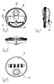
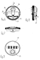
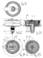
Figur 1- eine Explosionsdarstellung einer Ausführungsform einer erfindungsgemäßen Schließvorrichtung;
Figur 2- eine Hinteransicht eines Schlossträgers der in
Figur 1 gezeigten Schließvorrichtung, wobei ein Schieberiegel der Schließvorrichtung seine Ruhestellung einnimmt; - Figur 3
- eine Ansicht des in
Figur 2 gezeigten Schlossträgers aus Richtung des Pfeils A; Figur 4- eine Ansicht des in
Figur 2 gezeigten Schlossträgers aus Richtung des Pfeils B; Figur 5- eine Vorderansicht des in
Figur 2 gezeigten Schlossträgers; - Figur 6
- bis
Figur 9den Figuren 2bis 5 entsprechende Darstellungen des Schlossträgers, wobei der Schieberiegel seine Betriebsstellung einnimmt;Figur 10- eine Hinteransicht der Ausführungsform der erfindungsgemäßen Schließvorrichtung;
Figur 11- bis
Figur 13- eine Seitenansicht, eine Vorderansicht und den
Schnitt B - B in
Figur 11 der bzw. durch die Ausführungsform der erfindungsgemäßen Schließvorrichtung, wobei ein Sperrstück derselben sich außer Anlage mit Kupplungsscheiben eines Zahlenschlosses befindet; Figur 14- bis
Figur 17den Figuren 10bis 13 entsprechende Darstellungen, wobei das Sperrstück in Anlage an den Kupplungsscheiben des aus seinem Schlüsselgeheimnis verstellten Zahlenschlosses ist;Figur 18- bis
Figur 21den Figuren 10bis 13 bzw. 14bis 17 entsprechende Darstellungen, wobei das Sperrstück in Anlage an den Kupplungsscheiben des sich in seiner dem Schlüsselgeheimnis entsprechenden Stellung befindenden Zahlenschlosses ist;Figur 22- bis
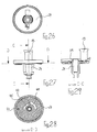
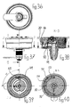
Figur 25- verschiedene Ansichten einer Unterplatte der erfindungsgemäßen Schließvorrichtung;
Figur 26- eine Rückansicht eines Schließriegels der erfindungsgemäßen Schließvorrichtung;
Figur 27- eine Seitenansicht des Schließriegels;
Figur 28- den Schnitt D - D in
Figur 27; Figur 29- den Schnitt C - C in
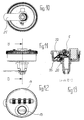
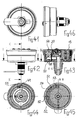
Figur 27; Figur 30- eine Explosionsdarstellung einer weiteren Ausführungsform der erfindungsgemäßen Schließvorrichtung;
Figur 31- eine Hinteransicht der in
Figur 30 gezeigten Ausführungsform der erfindungsgemäßen Schließvorrichtung; - Figur 32
- bis
Figur 35- eine Seitenansicht, den Schnitt C - C in Figur 32,
den Schnitt D - D in Figur 32 und den Schnitt P - P
in
Figur 33 der inFigur 30 gezeigten Ausführungsform der erfindungsgemäßen Schließvorrichtung, wobei ein Blockierelement sich in einer Halteposition befindet; Figur 36- bis
Figur 40den Figuren 31bis 35 entsprechende Darstellungen, wobei das Blockierelement sich in einer ersten Freigabenut befindet;Figur 41- bis
Figur 45den Figuren 31bis 35 bzw. 36bis 40 entsprechende Darstellungen, wobei das Blockierelement sich in einer zweiten Freigabenut befindet; undFigur 46- eine weitere Seitenansicht der in
Figur 30 gezeigten Ausführungsform der erfindungsgemäßen Schließvorrichtung.
- FIG. 1
- an exploded view of an embodiment of a closing device according to the invention;
- FIG. 2
- a rear view of a lock carrier of the closure device shown in Figure 1, wherein a sliding latch of the closing device assumes its rest position;
- FIG. 3
- a view of the lock carrier shown in Figure 2 from the direction of the arrow A;
- FIG. 4
- a view of the lock carrier shown in Figure 2 from the direction of arrow B;
- FIG. 5
- a front view of the lock carrier shown in Figure 2;
- FIG. 6
- to
- FIG. 9
- Figures 2 to 5 corresponding representations of the lock carrier, wherein the sliding latch assumes its operating position;
- FIG. 10
- a rear view of the embodiment of the locking device according to the invention;
- FIG. 11
- to
- FIG. 13
- a side view, a front view and the section B - B in Figure 11 of or by the embodiment of the locking device according to the invention, wherein a locking piece of the same is out of engagement with clutch discs of a combination lock;
- FIG. 14
- to
- FIG. 17
- Figures 10 to 13 corresponding representations, wherein the locking piece is in contact with the clutch discs of the adjusted from his key secret combination lock;
- FIG. 18
- to
- FIG. 21
- Figures 10 to 13 and 14 to 17 corresponding representations, wherein the locking piece is in contact with the clutch discs of the corresponding in its key secret position combination lock;
- FIG. 22
- to
- FIG. 25
- different views of a lower plate of the closing device according to the invention;
- FIG. 26
- a rear view of a locking bolt of the locking device according to the invention;
- FIG. 27
- a side view of the locking bolt;
- FIG. 28
- the section D - D in Figure 27;
- FIG. 29
- the section C - C in Figure 27;
- FIG. 30
- an exploded view of another embodiment of the locking device according to the invention;
- FIG. 31
- a rear view of the embodiment of the locking device according to the invention shown in Figure 30;
- FIG. 32
- to
- FIG. 35
- a side view, the section C - C in Figure 32, the section D - D in Figure 32 and the section P - P in Figure 33 of the embodiment of the locking device according to the invention shown in Figure 30, wherein a blocking element is in a holding position.
- FIG. 36
- to
- FIG. 40
- Figures 31 to 35 corresponding representations, wherein the blocking element is located in a first Freigabenut;
- FIG. 41
- to
- FIG. 45
- Figures 31 to 35 and 36 to 40 corresponding representations, wherein the blocking element is located in a second release groove; and
- FIG. 46
- a further side view of the embodiment shown in Figure 30 of the locking device according to the invention.
Eine in Figur 1 in Explosionsdarstellung gezeigte Ausführungsform
einer erfindungsgemäßen Schließvorrichtung 1 dient
beispielsweise dazu, ein in den Figuren nicht dargestelltes
Büro- oder anderes Möbelstück, z.B. einen Schaltschrank
od.dgl., zu verschließen.An embodiment shown in exploded view in Figure 1
a
Hierzu weist die Schließvorrichtung 1 im dargestellten Ausführungsbeispiel
ein Zahlenschloss 2 auf, dessen vier Zahlenräder
3 drehbar um eine Achse 4 des Zahlenschlosses 2 herum
angeordnet sind. Diese Zahlenräder 3 sitzen nicht unmittelbar
auf der Achse 4, sondern zwischen den Zahlenrädern 3 und der
Achse 4 sind koaxial zur Achse 4 bzw. zu den Zahlenrädern 3
Kupplungsscheiben 5 vorgesehen, von denen jeweils eine jeweils
einem Zahlenrad 3 zugeordnet ist. Die Kupplungsscheiben
5 besitzen einen Abschnitt mit größerem Durchmesser, in dessen
Außenumfang ein Einstich 6 ausgebildet ist. An dem sich
an den Abschnitt großen Durchmessers anschließenden Abschnitt
kleinen Durchmessers sind auf der Außenumfangsfläche Eingriffselemente
7 angeordnet. Mit dem Abschnitt kleinen Durchmessers,
der die Eingriffselemente 7 aufweist, ragt jede
Kupplungsscheibe 5 in Axialrichtung in das ihr zugeordnete
Zahlenrad 3, wobei auf der Innenumfangsfläche jedes Zahlenrads
3 Aufnahmeelemente 8 für die Eingriffselemente 7 der
Kupplungsscheibe 5 vorgesehen sind.For this purpose, the
Durch Axialverschiebung der Kupplungsscheiben 5 in Bezug auf
die Zahlenräder 3 können die kupplungsscheibenseitigen Eingriffselemente
7 in und außer Eingriff mit den zahlenradseitigen
Aufnahmeelementen 8 gestellt werden. Wenn die Zahlenräder
3 in Bezug auf die Kupplungsscheiben 5 und damit in Bezug
auf die Achse 4 frei drehbar sind, kann das Schlüsselgeheimnis
des Zahlenschlosses 2 eingestellt bzw. geändert werden.
Sobald der Eingriff zwischen den zahlenradseitigen Aufnahmeelementen
8 und den kupplungsscheibenseitigen Eingriffselementen
7 dann durch eine entsprechende Relativbewegung der
Kupplungsscheiben 5 wieder hergestellt wird, ist das neue
Schlüsselgeheimnis am Zahlenschloss 2 eingestellt.By axial displacement of the
Zur Axialverschiebung der Kupplungsscheiben 5 dient ein Codierblech
9, welches in Axialrichtung der Achse 4 verschieblich
innerhalb eines Schließwerkträgers 10 aufgenommen
ist. Das Codierblech 9 weist, wie aus Figur 1 hervorgeht, einen
nach unten kastenförmigen Querschnitt auf, wobei in der
Oberwand des Codierblechs 9 Ausnehmungen 11 ausgebildet sind,
durch die hindurch die Zahlenräder 3 vorstehen. Jede Ausnehmung
11 weist an ihrer in Figur 1 rechten Begrenzungswand einen
Steg 12 auf, der im montierten Zustand des Zahlenschlosses
2 jeweils mit einem Einstich 6 einer Kupplungsscheibe 5
in Eingriff ist.For axial displacement of the
Das Codierblech 9 wird in seiner Längsrichtung durch die Achse
4 durchragt, mittels der in aus dem Stand der Technik bekannter
Weise der Eingriff zwischen den Kupplungsscheiben 5
und den Zahlenrädern 3 aufhebbar ist.The
Das vorstehend geschilderte Zahlenschloss 2 mit den im folgenden
noch zu beschreibenden Bauteilen ist mit einem als zylindrisches
Schlüsselschloss ausgebildeten Sekundärschloss 13
an einem mit einer Abdeckplatte 14 versehenen Schlossträger
15 gehaltert. Das Zahlenschloss 2 ist mit dem Schlossträger
15, dem Sekundärschloss 13 und einem mit dem Schlossträger 15
verbundenen zylindrischen Gehäuse 16 in Bezug auf eine innerhalb
dieses zylindrischen Gehäuses 16 angeordnete Unterplatte
17 drehbar, wobei die Unterplatte 17 in Bezug auf die übrigen
vorstehend geschilderten Bauteile drehfest angeordnet ist.
Das Zahlenschloss 2 mit den es ausbildenden Bauteilen ist
insgesamt um die Unterplatte 17 verdrehbar, die ihrerseits in
geeigneter Weise am Möbelstück od.dgl. fixiert ist.The above-described
Zur Betätigung der Achse 4 zwecks Ver- bzw. Neueinstellung
des Schlüsselgeheimnisses des Zahlenschlosses 2 ist das Codierblech
9 mit einem Vorsprung 18 versehen, der bei sich in
ihrer Offenstellung befindlicher Schließvorrichtung 1 betätigbar
ist.For actuating the
Im Schließwerkträger 10 ist eine Multifunktionsfeder 19 angeordnet,
mittels der ein oberhalb der Multifunktionsfeder 19
innerhalb des Schließwerkträgers 10 angeordnetes Sperrstück
20 des Zahlenschlosses 2 in Richtung auf dessen Freigabestellung
vorgespannt wird.In
Das Sperrstück 20 sitzt zwischen der Multifunktionsfeder 19
und dem Codierblech 9 und liegt mit seiner Oberfläche gegen
die Außenumfangsflächen der Kupplungsscheiben 5 an. Es kann
seine Freigabestellung nur dann einnehmen, wenn bei an den
Zahlenrädern 3 eingestelltem Schlüsselgeheimnis des Zahlenschlosses
2 entsprechend die Kupplungsscheiben 5 mit ihren
abgeflachten Außenumfangsabschnitten 21 dem Sperrstück 20 zugewandt
sind. Dann wird letzteres durch die Multifunktionsfeder
19 in in Figur 1 aufwärtiger Richtung gedrückt.The locking
Sobald an den Zahlenrädern 3 das Schlüsselgeheimnis des Zahlenschlosses
2 eingestellt und das Sperrstück 20 mittels der
Multifunktionsfeder 19 aufwärts versetzt ist, greift eine in
Figur 1 schräg abwärts verlaufende Nase 22 des Sperrstücks 20
in eine Ausnehmung 23 eines Schließriegels 24 ein, mit der
Folge, dass der Schließriegel 24 gemeinsam mit dem Zahlenschloss
2 bzw. dem Schlossträger 15 in Bezug auf die Unterplatte
17 drehbar ist.Once at the number wheels 3 the key secret of the
Der Schließriegel 24 durchragt die Unterplatte 17 in axialer
Richtung und ist an seinem die Unterplatte 17 durchragenden
Ende mit einem Schließglied 25 verbunden, welches durch Drehung
des Schließriegels 24 in und außer Eingriff mit einer in
den Figuren nicht gezeigten Schlossfalle verstellbar ist.The locking
Zwischen dem Schlossträger 15 einerseits und der Unterplatte
17 andererseits ist eine Positioniervorrichtung vorgesehen,
mittels der der Schlossträger 15 in einer Drehstellung in Bezug
auf die Unterplatte 17 positionierbar ist, in der die Nase
22 des Sperrstücks 20 des Zahlenschlosses 2 mit der Ausnehmung
23 des Schließriegels 24 fluchtet.Between the
Diese Positioniervorrichtung ist in Form einer Kugelrastung
ausgestaltet und hat im dargestellten Ausführungsbeispiel eine
mittels einer Vorspannfeder 26 in Richtung auf die Unterplatte
17 vorgespannte Kugel 27, wobei die Vorspannfeder 26
und die Kugel 27 in einer Aufnahmenut 28 des Schlossträgers
15 angeordnet sind. Der Kugel 27 zugeordnet ist eine Ausnehmung
29 auf der Stirnseite einer zylindrischen Wandung 30 der
Unterplatte 17. Wenn die Kugel 27 mit der Ausnehmung 29 in
Fluchtung gerät, wird sie durch die Vorspannfeder 26 geringfügig
in die Ausnehmung 29 hineingedrückt, so dass eine exakte
Positionierung des Schlossträgers 15 in Bezug auf die Unterplatte
17 möglich ist. Durch einfaches Weiterdrehen des
Schlossträgers 15 lässt sich die Positionierung desselben in
Bezug auf die Unterplatte 17 aufheben. This positioning device is in the form of a ball catch
configured and has a in the illustrated embodiment
by means of a biasing
Bei einer Ausführungsform der Schließvorrichtung 1, bei der
das Schlüsselgeheimnis des Zahlenschlosses 2 mittels des Sekundärschlosses
13 auffindbar ist, ist zwischen dem Schließwerkträger
10 und dem Schließriegel 24 ein Schieberiegel 31
vorgesehen. Der Schieberiegel 31 hat eine etwa mittige Ausnehmung
32, die von einem zylindrischen Vorsprung 33 des
Schließriegels 24 durchragt wird. Die Form der Ausnehmung 32
des Schieberiegels 31 ist so gewählt, dass der Schieberiegel
31 in Bezug auf die zylindrische Ausnehmung 33 des Schließriegels
hin und her bewegbar ist.In one embodiment of the
Der Schieberiegel 31 hat einen Betätigungsabschnitt 34 und -
diesem diametral gegenüberliegend - eine Stellnase 35. In
seiner Ruhestellung befindet sich die Stellnase 35 des Schieberiegels
31, wie sich insbesondere aus Figur 2 und dem
Schnitt B - B aus Figur 17 ergibt, außer Anlage mit der Nase
22 des Sperrstücks 20, das gegen die Kupplungsscheiben 5 des
aus dem Schlüsselgeheimnis heraus verstellten Zahlenschlosses
2 anliegt. Aus seiner Ruhestellung ist der Schieberiegel 31
in seine in Figur 6 und in Figur 13 dargestellte Betriebsstellung
verstellbar, indem das Sekundär- bzw. Zylinderschloss
13 aus seiner in Figur 5 gezeigten Stellung in seine
in Figur 9 gezeigte Stellung gedreht wird. Bei dieser Drehung
wird der Schieberiegel 31 durch auf seinen Betätigungsabschnitt
34 einwirkende, an der Unterseite des Sekundär- bzw.
Zylinderschlosses 13 vorgesehene Stellglieder 36 in die in
Figur 6 gezeigte Position geschoben, und zwar gegen die Kraft
einer Feder 37, mittels der der Schieberiegel 31 in seine Ruhestellung
vorgespannt ist. Bei dieser Verstellung des Schieberiegels
31 gerät dessen Stellnase 35 in Anlage gegen die
Nase 22 des Sperrstücks 20 und drückt diese Nase 22 in die
Zeichnungsebene in Figur 6 bzw. nach rechts in Figur 13, mit
der Folge, dass das Sperrstück 20 außer Anlage mit den Umfangsflächen
der Kupplungsscheiben 5 des Zahlenschlosses gerät.
An der Multifunktionsfeder 19 vorgesehene Federarme können
nun mit vorzugsweise als Herzscheiben ausgebildeten, mit
den Kupplungsscheiben verbundenen Stellelementen zusammenwirken,
um die Zahlenräder 3 des Zahlenschlosses 2 in deren dem
Schlüsselgeheimnis des Zahlenschlosses 2 entsprechende Stellungen
zu verdrehen.The sliding
Bei einer Ausführungsform der Schließvorrichtung 1, bei der
eine automatische Verwischung des Schlüsselgeheimnisses des
Zahlenschlosses 2 realisierbar sein soll, ist die zylindrische
Wandung 30 der Unterplatte 17 auf ihrer Innenseite mit
einer Kulissenführung 38 versehen, wie dies am besten aus Figur
25 hervorgeht. Wenn der Schlossträger 15 mit dem Zahlenschloss
2 und damit dem Sperrstück 20 nach einem Öffnen der
Schließvorrichtung 1 in Bezug auf die Unterplatte 17 verdreht
wird, wird die Nase 22 des Sperrstücks 20 durch Schrägen 39
bzw. 40 der Kulissenführung 38 in in Figur 25 und 1 aufwärtiger
Richtung bewegt, so dass die Anlage zwischen dem Sperrstück
20 und den Umfangsflächen der Kupplungsscheiben 5 aufgehoben
wird, mit der Folge, dass an der Multifunktionsfeder
19 vorgesehene Federarme über mit den Kupplungsscheiben 5
verbundene, vorzugsweise als Herzscheiben ausgebildete Stellglieder
die Kupplungsscheiben 5 und damit die Zahlenräder 3
aus dem eingestellten Schlüsselgeheimnis des Zahlenschlosses
2 verstellen.In one embodiment of the
Zur Einstellung der Rechtsdrehung und der Linksdrehung der
Schließvorrichtung 1 weist letztere einen Schieber 41 auf,
der von der Rückseite der Schließvorrichtung 1 her betätigbar
und rastbar ist. Der Schieber 41 hat einen Steuernocken 42
und ist in einer in der Unterplatte vorgesehenen Führnut 43
geführt. Der Steuernocken 42 des Schiebers 41 kann in eine
einer Linksdrehung oder eine einer Rechtsdrehung der Schließvorrichtung
1 entsprechende Position verbracht werden, wobei
jeder Drehung der Schließvorrichtung 1 jeweils eine Kulissenausnehmung
44 bzw. 45 im Schließriegel 24 zugeordnet ist.
Wenn der Steuernocken 42 sich in der in Figur 28 gezeigten
Position befindet, ist die Schließvorrichtung für Rechtsdrehung
eingerichtet.To set the clockwise rotation and the counterclockwise rotation of
Zwischen dem Schließriegel 24 einerseits und der Unterplatte
17 andererseits ist eine weitere Positioniervorrichtung vorgesehen,
mittels der der Schließriegel 24 in definierten
Stellungen in Bezug auf die Unterplatte 17 positionierbar
ist. Diese weitere Positioniervorrichtung hat ebenfalls eine
Feder 46 sowie eine Kugel 47, die mittels der Feder 46 in
Richtung auf die Unterplatte 17 gedrückt wird. In der Unterplatte
sind in der Zustellung und in der Offenstellung des
Schließriegels 24 Ausnehmungen 48 vorgesehen, in die die Kugel
47 mittels der Feder 46 einrastet, wenn sich der Schließriegel
24 in der betreffenden Stellung befindet.Between the locking
Wenn die Schließvorrichtung 1 geschlossen ist, ist der das
Zahlenschloss 2 und das Sekundärschloss 13 halternde Schlossträger
15 in Bezug auf die Unterplatte 17 und den mittels der
weiteren Positioniervorrichtung 46, 47, 48 an der Unterplatte
17 positionierten Schließriegel 24 frei drehbar.When the
Bei Einstellung des Schlüsselgeheimnisses des Zahlenschlosses
2 wird das Sperrstück 20 so vorgespannt, dass seine Nase 22
bei einer Drehung des Schlossträgers 15 in die Ausnehmung 23
des Schließriegels 24 einrastet, so dass nach dieser Rastung
der Schließriegel 24 mit dem Schlossträger 15 drehbar ist, um
das Schließglied 25 außer Eingriff mit der in Figuren nicht
gezeigten Schlossfalle zu bringen.When setting the key secret of the
Alternativ ist es möglich, den Schlossträger 15 zunächst mittels
der ersten Positioniervorrichtung 26, 27, 28, 29 zu positionieren,
so dass bereits vor der Einstellung des Schlüsselgeheimnisses
des Zahlenschlosses 2 die Nase 22 des Sperrstücks
20 der Ausnehmung 23 des Schließriegels 24 gegenüberliegt.
Im letzteren Fall können jedwede Beanspruchungen von
Bauteilen der Schließvorrichtung 1, die der Verriegelung,
Blockierung od.dgl. dienen, ausgeschlossen werden.Alternatively, it is possible to first lock means 15 by means of
the
Eine anhand der Figuren 30 bis 46 im folgenden näher beschriebene
Ausführungsform der erfindungsgemäßen Schließvorrichtung
1 unterscheidet sich von der vorstehend beschriebenen
durch ein zwischen dem Schließriegel 24 einerseits und
dem Festteil bzw. der Unterplatte 17 andererseits wirkendes
Blockierelement in Form eines Druckriegels 49. Der Druckriegel
49 hat an seiner in Figur 30 Unterseite einen Zapfen 50,
der in eine Kulisseneinrichtung 51 vorsteht, die auf der dem
Druckriegel 49 zugewandten Seite der Unterplatte 17 ausgebildet
ist.One with reference to Figures 30 to 46 described in more detail below
Embodiment of the closing device according to the
Zu der Kulisseneinrichtung 51 gehören, wie sich am besten aus
den Figuren 30, 35, 40 und 45 ergibt, eine Halteposition 52,
eine erste Freigabenut 53 und eine zweite Freigabenut 54, wobei
sich die erste Freigabenut 53 radial einwärts der zweiten
Freigabenut 54 befindet und wobei in Radialrichtung zwischen
den beiden Freigabenuten 53, 54 die Halteposition 52 der Kulisseneinrichtung
51 ausgebildet ist. To the
Der Druckriegel 49 ist in Radialrichtung verschieblich in einer
Führung 57, die im Schließriegel 24 ausgebildet ist, gehaltert.
Dem Druckriegel 49 zugeordnet ist eine Schieberfeder
55, die ebenfalls in einer entsprechenden Ausnehmung des
Schließriegels 24 gehaltert ist und die so angeordnet und
ausgebildet ist, daß sich im unbelasteten Zustand der Schieberfeder
55 der Druckriegel 49 mit seinem Zapfen 50 in der
Halteposition 52 der Kulisseneinrichtung 51 befindet. In dieser
Position des Druckriegels 49 ist eine Drehung zwischen
dem Schließriegel 24 und dem Festteil bzw. der Unterplatte
17, die in bezug auf ein Möbelstück od.dgl. fest angeordnet
ist, nicht möglich. Der Schlossträger 15 hingegen ist nach
wie vor frei in bezug auf das Festteil bzw. die Unterplatte
17 drehbar.The
Wenn am Zahlenschloss 2 durch entsprechende Verstellung der
Zahlenräder 3 das Schlüsselgeheimnis eingestellt wird, drückt
das Sperrstück 20, wie am besten aus einer Zusammenschau der
Figuren 38 und 40 hervorgeht, unterstützt von einer Druckfeder
56, die zwischen dem Sperrstück 20 und dem Schließwerkträger
10 bzw. dem Schlossträger 15 angeordnet ist, den
Druckriegel 49 bzw. dessen Zapfen 50 aus der Halteposition 52
der Kulisseneinrichtung 51 heraus in deren radial innere erste
Freigabenut 53. Nunmehr ist der Schließriegel 24 in bezug
auf das Festteil bzw. die Unterplatte 17 drehbar, da der Blockiereingriff
zwischen dem druckriegelseitigen Zapfen 50 und
der Halteposition 52 der Kulisseneinrichtung 51 aufgehoben
ist.If at the
Wenn nach einer Verstellung des Zahlenschlosses 2 aus dem
Schlüsselgeheimnis heraus das Sperrstück 20 zurück in die in
Figur 33 gezeigte Position verstellt wird, wird der Druckriegel
49 mittels der Schieberfeder 55 in die in Figur 34 gezeigte
Position verstellt, in der der Zapfen 50 des Druckriegels
49 wieder in die Halteposition 52 der Kulisseneinrichtung
51 verstellt ist. Die Schieberfeder 55 nimmt nämlich,
sofern die Vorspannkraft des Sperrstücks 20 auf den Druckriegel
49 aufgehoben ist, wieder ihre unbelastete, in Figur 34
gezeigte Position ein, in der sie mit dem Druckriegel 49 montiert
ist. Eine Relativdrehung zwischen dem Schließriegel 24
und dem Festteil bzw. der Unterplatte 17 ist nun wieder unmöglich.If after an adjustment of the
Wenn der Druckriegel 49 durch Betätigung des Sekundärschlosses
13 über den Schieberiegel 31 gegen die Kraft der Schieberfeder
55 in radial auswärtiger Richtung verstellt wird,
gerät der Zapfen 50 des Druckriegels 49, wie am besten aus
einer Zusammenschau der Figuren 43 und 45 hervorgeht, aus der
Halteposition 52 der Kulisseneinrichtung 51 in radial auswärtiger
Richtung in die zweite Freigabenut 54 der Kulisseneinrichtung
51. Bei dieser Bewegung des Druckriegels 49 drückt
dieser das Sperrstück 20 des Zahlenschlosses 2 gegen die
Kraft der Druckfeder 56 ebenfalls radial auswärts, so daß die
Anlage zwischen dem Sperrstück 20 einerseits und den Kupplungsscheiben
5 des Zahlenschlosses 2 andererseits aufgehoben
wird. Die Zahlenräder 3 des Zahlenschlosses 2 sind dann mittels
der Multifunktionsfeder 19, die auf die Kupplungsscheiben
5 einwirkt, in ihre dem Schlüsselgeheimnis des Zahlenschlosses
2 entsprechende Position verstellbar.When the
Sofern sich das Zahlenschloss 2 und das Sekundärschloss 13
und damit die Schließeinrichtung 1 in ihrer Schließposition
befinden, kann der Schließriegel 24 in bezug auf das Festteil
bzw. die Unterplatte 17, die am Möbelstück od.dgl. fixiert
ist, nicht gedreht werden. Bei der anhand der Figuren 30 bis
46 beschriebenen Ausführungsform der Schließeinrichtung 1 ist
es somit auch bei nicht geschränkten bzw. nicht überlappenden
Türen, Klappen od.dgl. von Möbelstücken nicht möglich, das
Schließglied 25 der Schließeinrichtung 1, das drehfest am
Schließriegel 24 sitzt, aus seiner Blockier- in seine Freigabestellung
zu bringen, selbst für den Fall nicht, daß wegen
der nicht geschränkten bzw. nicht überlappenden Ausgestaltung
der Türen, Tore od.dgl. mittels einer Scheckkarte od.dgl.
hinter die Tür, das Tor od.dgl. vorgedrungen werden kann.If the
Claims (23)
Applications Claiming Priority (2)
| Application Number | Priority Date | Filing Date | Title |
|---|---|---|---|
| DE102004012000 | 2004-03-10 | ||
| DE102004012000A DE102004012000A1 (en) | 2004-03-10 | 2004-03-10 | Closing device for containers, doors, cabinets, furniture od. Like. |
Publications (3)
| Publication Number | Publication Date |
|---|---|
| EP1574641A2 true EP1574641A2 (en) | 2005-09-14 |
| EP1574641A3 EP1574641A3 (en) | 2006-05-03 |
| EP1574641B1 EP1574641B1 (en) | 2010-07-28 |
Family
ID=34813662
Family Applications (1)
| Application Number | Title | Priority Date | Filing Date |
|---|---|---|---|
| EP04029499A Expired - Lifetime EP1574641B1 (en) | 2004-03-10 | 2004-12-14 | Locking device for containers, doors, cabinets, furniture or the like. |
Country Status (3)
| Country | Link |
|---|---|
| EP (1) | EP1574641B1 (en) |
| AT (1) | ATE475765T1 (en) |
| DE (2) | DE102004012000A1 (en) |
Cited By (5)
| Publication number | Priority date | Publication date | Assignee | Title |
|---|---|---|---|---|
| EP2942457A1 (en) * | 2014-05-08 | 2015-11-11 | W&F Locks OHG | Locking device |
| CN105178718A (en) * | 2015-08-18 | 2015-12-23 | 谢龙明 | Rotary knob type coded lock |
| DE102014109224A1 (en) * | 2014-07-01 | 2016-01-07 | S. Franzen Söhne GmbH | Closure with the opening of the shutter automatically deleting coding of a combination lock |
| WO2018157967A1 (en) * | 2017-03-03 | 2018-09-07 | Sudhaus Gmbh & Co. Kg | Locking device for containers, doors, cabinets, furniture, or the like |
| WO2024007353A1 (en) * | 2022-07-08 | 2024-01-11 | 厦门美科安防科技股份有限公司 | Auxiliary structure for resetting number wheel combination lock |
Families Citing this family (1)
| Publication number | Priority date | Publication date | Assignee | Title |
|---|---|---|---|---|
| DE102009016954B4 (en) | 2009-04-14 | 2024-02-01 | Sudhaus Gmbh & Co. Kg | Lock device |
Citations (3)
| Publication number | Priority date | Publication date | Assignee | Title |
|---|---|---|---|---|
| US2251145A (en) | 1940-02-28 | 1941-07-29 | Dudley Lock Corp | Key and combination operated lock |
| US3521471A (en) | 1967-04-05 | 1970-07-21 | Donato Aretola | Combination locks |
| DE19719392A1 (en) | 1997-05-07 | 1998-11-12 | Siegfried Merklein | Door handle with numerical lock |
Family Cites Families (3)
| Publication number | Priority date | Publication date | Assignee | Title |
|---|---|---|---|---|
| DE9106293U1 (en) * | 1991-05-22 | 1991-09-12 | Solidor AG, O-5630 Heiligenstadt | Code lock |
| DE19906371A1 (en) * | 1999-02-16 | 2000-08-24 | Siegfried Merklein | Door handle with a combination lock has an integrated structure forming a complete door handle unit which is robust and easily cleaned with the required security of entry |
| DE10206991B4 (en) * | 2002-02-19 | 2007-04-12 | Sudhaus Gmbh & Co. | Combination lock for cabinets, furniture or the like |
-
2004
- 2004-03-10 DE DE102004012000A patent/DE102004012000A1/en not_active Withdrawn
- 2004-12-14 EP EP04029499A patent/EP1574641B1/en not_active Expired - Lifetime
- 2004-12-14 DE DE502004011442T patent/DE502004011442D1/en not_active Expired - Lifetime
- 2004-12-14 AT AT04029499T patent/ATE475765T1/en active
Patent Citations (3)
| Publication number | Priority date | Publication date | Assignee | Title |
|---|---|---|---|---|
| US2251145A (en) | 1940-02-28 | 1941-07-29 | Dudley Lock Corp | Key and combination operated lock |
| US3521471A (en) | 1967-04-05 | 1970-07-21 | Donato Aretola | Combination locks |
| DE19719392A1 (en) | 1997-05-07 | 1998-11-12 | Siegfried Merklein | Door handle with numerical lock |
Cited By (8)
| Publication number | Priority date | Publication date | Assignee | Title |
|---|---|---|---|---|
| EP2942457A1 (en) * | 2014-05-08 | 2015-11-11 | W&F Locks OHG | Locking device |
| DE102014006673A1 (en) * | 2014-05-08 | 2015-11-12 | W&F Locks Ohg | lock device |
| DE102014109224A1 (en) * | 2014-07-01 | 2016-01-07 | S. Franzen Söhne GmbH | Closure with the opening of the shutter automatically deleting coding of a combination lock |
| CN105178718A (en) * | 2015-08-18 | 2015-12-23 | 谢龙明 | Rotary knob type coded lock |
| WO2018157967A1 (en) * | 2017-03-03 | 2018-09-07 | Sudhaus Gmbh & Co. Kg | Locking device for containers, doors, cabinets, furniture, or the like |
| US12371926B2 (en) | 2017-03-03 | 2025-07-29 | Sudhaus Gmbh & Co. Kg | Lock |
| WO2024007353A1 (en) * | 2022-07-08 | 2024-01-11 | 厦门美科安防科技股份有限公司 | Auxiliary structure for resetting number wheel combination lock |
| GB2631856A (en) * | 2022-07-08 | 2025-01-15 | Xiamen Make Security Tech Co Ltd | Auxiliary structure for resetting number wheel combination lock |
Also Published As
| Publication number | Publication date |
|---|---|
| EP1574641A3 (en) | 2006-05-03 |
| EP1574641B1 (en) | 2010-07-28 |
| DE502004011442D1 (en) | 2010-09-09 |
| ATE475765T1 (en) | 2010-08-15 |
| DE102004012000A1 (en) | 2005-09-22 |
Similar Documents
| Publication | Publication Date | Title |
|---|---|---|
| DE102009016954B4 (en) | Lock device | |
| EP2174571B1 (en) | Opening device for a removal guide and catch mechanism | |
| EP3589807B1 (en) | Locking device for containers, doors, cabinets, furniture, or the like | |
| EP0819810B1 (en) | Fitting for a lock | |
| DE102014104141A1 (en) | Actuating handle | |
| EP0235349B1 (en) | Lock for the hand brake lever of a motor vehicle | |
| EP1722048B1 (en) | Fitting, in particular window fitting | |
| EP1574641B1 (en) | Locking device for containers, doors, cabinets, furniture or the like. | |
| EP1267020B1 (en) | Locking device | |
| EP0938113B1 (en) | Safety switch | |
| EP0867583B1 (en) | Locking device for a receptacle | |
| DE19928729A1 (en) | Window or door handle with inbuilt locking facility | |
| DE102008044934A1 (en) | safety device | |
| EP0001283A1 (en) | Braked castor for movable apparatus, especially refuse or similar containers | |
| DE3040586C2 (en) | Surface lock with a sliding latch | |
| AT394241B (en) | Lock | |
| EP2034110B1 (en) | Rosette with a securing device | |
| DE102010062932A1 (en) | Resting binder for pivotally connecting two vehicle parts with each other, has fitting part and another fitting part that is mounted on former fitting part around rotating axis | |
| DE10206991B4 (en) | Combination lock for cabinets, furniture or the like | |
| DE102005026930B4 (en) | padlock | |
| DE10140209A1 (en) | :Lock consisting of combination and secondary locks has number wheels, housing trough and cipher setting device | |
| EP0880632B1 (en) | Lock armature for doors, gates or the like, particularly garage doors | |
| EP1256670B1 (en) | Window handle lock | |
| EP2568099A2 (en) | Swing arm clamp | |
| DE29607192U1 (en) | Combination lock for furniture, mailboxes and the like. |
Legal Events
| Date | Code | Title | Description |
|---|---|---|---|
| PUAI | Public reference made under article 153(3) epc to a published international application that has entered the european phase |
Free format text: ORIGINAL CODE: 0009012 |
|
| AK | Designated contracting states |
Kind code of ref document: A2 Designated state(s): AT BE BG CH CY CZ DE DK EE ES FI FR GB GR HU IE IS IT LI LT LU MC NL PL PT RO SE SI SK TR |
|
| AX | Request for extension of the european patent |
Extension state: AL BA HR LV MK YU |
|
| PUAL | Search report despatched |
Free format text: ORIGINAL CODE: 0009013 |
|
| AK | Designated contracting states |
Kind code of ref document: A3 Designated state(s): AT BE BG CH CY CZ DE DK EE ES FI FR GB GR HU IE IS IT LI LT LU MC NL PL PT RO SE SI SK TR |
|
| AX | Request for extension of the european patent |
Extension state: AL BA HR LV MK YU |
|
| REG | Reference to a national code |
Ref country code: HK Ref legal event code: DE Ref document number: 1085778 Country of ref document: HK |
|
| 17P | Request for examination filed |
Effective date: 20060929 |
|
| AKX | Designation fees paid |
Designated state(s): AT BE BG CH CY CZ DE DK EE ES FI FR GB GR HU IE IS IT LI LT LU MC NL PL PT RO SE SI SK TR |
|
| 17Q | First examination report despatched |
Effective date: 20070524 |
|
| GRAP | Despatch of communication of intention to grant a patent |
Free format text: ORIGINAL CODE: EPIDOSNIGR1 |
|
| GRAS | Grant fee paid |
Free format text: ORIGINAL CODE: EPIDOSNIGR3 |
|
| GRAA | (expected) grant |
Free format text: ORIGINAL CODE: 0009210 |
|
| AK | Designated contracting states |
Kind code of ref document: B1 Designated state(s): AT BE BG CH CY CZ DE DK EE ES FI FR GB GR HU IE IS IT LI LT LU MC NL PL PT RO SE SI SK TR |
|
| REG | Reference to a national code |
Ref country code: GB Ref legal event code: FG4D Free format text: NOT ENGLISH |
|
| REG | Reference to a national code |
Ref country code: CH Ref legal event code: EP |
|
| REG | Reference to a national code |
Ref country code: IE Ref legal event code: FG4D Free format text: LANGUAGE OF EP DOCUMENT: GERMAN |
|
| REF | Corresponds to: |
Ref document number: 502004011442 Country of ref document: DE Date of ref document: 20100909 Kind code of ref document: P |
|
| REG | Reference to a national code |
Ref country code: NL Ref legal event code: VDEP Effective date: 20100728 |
|
| LTIE | Lt: invalidation of european patent or patent extension |
Effective date: 20100728 |
|
| PG25 | Lapsed in a contracting state [announced via postgrant information from national office to epo] |
Ref country code: FI Free format text: LAPSE BECAUSE OF FAILURE TO SUBMIT A TRANSLATION OF THE DESCRIPTION OR TO PAY THE FEE WITHIN THE PRESCRIBED TIME-LIMIT Effective date: 20100728 Ref country code: LT Free format text: LAPSE BECAUSE OF FAILURE TO SUBMIT A TRANSLATION OF THE DESCRIPTION OR TO PAY THE FEE WITHIN THE PRESCRIBED TIME-LIMIT Effective date: 20100728 Ref country code: NL Free format text: LAPSE BECAUSE OF FAILURE TO SUBMIT A TRANSLATION OF THE DESCRIPTION OR TO PAY THE FEE WITHIN THE PRESCRIBED TIME-LIMIT Effective date: 20100728 |
|
| PG25 | Lapsed in a contracting state [announced via postgrant information from national office to epo] |
Ref country code: PT Free format text: LAPSE BECAUSE OF FAILURE TO SUBMIT A TRANSLATION OF THE DESCRIPTION OR TO PAY THE FEE WITHIN THE PRESCRIBED TIME-LIMIT Effective date: 20101129 Ref country code: BG Free format text: LAPSE BECAUSE OF FAILURE TO SUBMIT A TRANSLATION OF THE DESCRIPTION OR TO PAY THE FEE WITHIN THE PRESCRIBED TIME-LIMIT Effective date: 20101028 Ref country code: CY Free format text: LAPSE BECAUSE OF FAILURE TO SUBMIT A TRANSLATION OF THE DESCRIPTION OR TO PAY THE FEE WITHIN THE PRESCRIBED TIME-LIMIT Effective date: 20100728 Ref country code: IS Free format text: LAPSE BECAUSE OF FAILURE TO SUBMIT A TRANSLATION OF THE DESCRIPTION OR TO PAY THE FEE WITHIN THE PRESCRIBED TIME-LIMIT Effective date: 20101128 Ref country code: PL Free format text: LAPSE BECAUSE OF FAILURE TO SUBMIT A TRANSLATION OF THE DESCRIPTION OR TO PAY THE FEE WITHIN THE PRESCRIBED TIME-LIMIT Effective date: 20100728 Ref country code: SI Free format text: LAPSE BECAUSE OF FAILURE TO SUBMIT A TRANSLATION OF THE DESCRIPTION OR TO PAY THE FEE WITHIN THE PRESCRIBED TIME-LIMIT Effective date: 20100728 |
|
| REG | Reference to a national code |
Ref country code: IE Ref legal event code: FD4D |
|
| PG25 | Lapsed in a contracting state [announced via postgrant information from national office to epo] |
Ref country code: GR Free format text: LAPSE BECAUSE OF FAILURE TO SUBMIT A TRANSLATION OF THE DESCRIPTION OR TO PAY THE FEE WITHIN THE PRESCRIBED TIME-LIMIT Effective date: 20101029 Ref country code: SE Free format text: LAPSE BECAUSE OF FAILURE TO SUBMIT A TRANSLATION OF THE DESCRIPTION OR TO PAY THE FEE WITHIN THE PRESCRIBED TIME-LIMIT Effective date: 20100728 |
|
| PG25 | Lapsed in a contracting state [announced via postgrant information from national office to epo] |
Ref country code: DK Free format text: LAPSE BECAUSE OF FAILURE TO SUBMIT A TRANSLATION OF THE DESCRIPTION OR TO PAY THE FEE WITHIN THE PRESCRIBED TIME-LIMIT Effective date: 20100728 Ref country code: IE Free format text: LAPSE BECAUSE OF FAILURE TO SUBMIT A TRANSLATION OF THE DESCRIPTION OR TO PAY THE FEE WITHIN THE PRESCRIBED TIME-LIMIT Effective date: 20100728 |
|
| PG25 | Lapsed in a contracting state [announced via postgrant information from national office to epo] |
Ref country code: CZ Free format text: LAPSE BECAUSE OF FAILURE TO SUBMIT A TRANSLATION OF THE DESCRIPTION OR TO PAY THE FEE WITHIN THE PRESCRIBED TIME-LIMIT Effective date: 20100728 Ref country code: IT Free format text: LAPSE BECAUSE OF FAILURE TO SUBMIT A TRANSLATION OF THE DESCRIPTION OR TO PAY THE FEE WITHIN THE PRESCRIBED TIME-LIMIT Effective date: 20100728 Ref country code: SK Free format text: LAPSE BECAUSE OF FAILURE TO SUBMIT A TRANSLATION OF THE DESCRIPTION OR TO PAY THE FEE WITHIN THE PRESCRIBED TIME-LIMIT Effective date: 20100728 Ref country code: RO Free format text: LAPSE BECAUSE OF FAILURE TO SUBMIT A TRANSLATION OF THE DESCRIPTION OR TO PAY THE FEE WITHIN THE PRESCRIBED TIME-LIMIT Effective date: 20100728 Ref country code: EE Free format text: LAPSE BECAUSE OF FAILURE TO SUBMIT A TRANSLATION OF THE DESCRIPTION OR TO PAY THE FEE WITHIN THE PRESCRIBED TIME-LIMIT Effective date: 20100728 |
|
| PLBE | No opposition filed within time limit |
Free format text: ORIGINAL CODE: 0009261 |
|
| STAA | Information on the status of an ep patent application or granted ep patent |
Free format text: STATUS: NO OPPOSITION FILED WITHIN TIME LIMIT |
|
| PG25 | Lapsed in a contracting state [announced via postgrant information from national office to epo] |
Ref country code: ES Free format text: LAPSE BECAUSE OF FAILURE TO SUBMIT A TRANSLATION OF THE DESCRIPTION OR TO PAY THE FEE WITHIN THE PRESCRIBED TIME-LIMIT Effective date: 20101108 |
|
| 26N | No opposition filed |
Effective date: 20110429 |
|
| PG25 | Lapsed in a contracting state [announced via postgrant information from national office to epo] |
Ref country code: MC Free format text: LAPSE BECAUSE OF NON-PAYMENT OF DUE FEES Effective date: 20101231 |
|
| REG | Reference to a national code |
Ref country code: DE Ref legal event code: R097 Ref document number: 502004011442 Country of ref document: DE Effective date: 20110429 |
|
| REG | Reference to a national code |
Ref country code: HK Ref legal event code: WD Ref document number: 1085778 Country of ref document: HK |
|
| PG25 | Lapsed in a contracting state [announced via postgrant information from national office to epo] |
Ref country code: LU Free format text: LAPSE BECAUSE OF NON-PAYMENT OF DUE FEES Effective date: 20101214 Ref country code: HU Free format text: LAPSE BECAUSE OF FAILURE TO SUBMIT A TRANSLATION OF THE DESCRIPTION OR TO PAY THE FEE WITHIN THE PRESCRIBED TIME-LIMIT Effective date: 20110129 |
|
| PG25 | Lapsed in a contracting state [announced via postgrant information from national office to epo] |
Ref country code: TR Free format text: LAPSE BECAUSE OF FAILURE TO SUBMIT A TRANSLATION OF THE DESCRIPTION OR TO PAY THE FEE WITHIN THE PRESCRIBED TIME-LIMIT Effective date: 20100728 |
|
| REG | Reference to a national code |
Ref country code: FR Ref legal event code: PLFP Year of fee payment: 12 |
|
| REG | Reference to a national code |
Ref country code: FR Ref legal event code: PLFP Year of fee payment: 13 |
|
| REG | Reference to a national code |
Ref country code: FR Ref legal event code: PLFP Year of fee payment: 14 |
|
| PGFP | Annual fee paid to national office [announced via postgrant information from national office to epo] |
Ref country code: CH Payment date: 20191220 Year of fee payment: 16 |
|
| REG | Reference to a national code |
Ref country code: CH Ref legal event code: PL |
|
| PG25 | Lapsed in a contracting state [announced via postgrant information from national office to epo] |
Ref country code: LI Free format text: LAPSE BECAUSE OF NON-PAYMENT OF DUE FEES Effective date: 20201231 Ref country code: CH Free format text: LAPSE BECAUSE OF NON-PAYMENT OF DUE FEES Effective date: 20201231 |
|
| PGFP | Annual fee paid to national office [announced via postgrant information from national office to epo] |
Ref country code: AT Payment date: 20211221 Year of fee payment: 18 |
|
| PGFP | Annual fee paid to national office [announced via postgrant information from national office to epo] |
Ref country code: BE Payment date: 20211222 Year of fee payment: 18 |
|
| PGFP | Annual fee paid to national office [announced via postgrant information from national office to epo] |
Ref country code: GB Payment date: 20221222 Year of fee payment: 19 Ref country code: FR Payment date: 20221220 Year of fee payment: 19 |
|
| PGFP | Annual fee paid to national office [announced via postgrant information from national office to epo] |
Ref country code: DE Payment date: 20230224 Year of fee payment: 19 |
|
| P01 | Opt-out of the competence of the unified patent court (upc) registered |
Effective date: 20230413 |
|
| REG | Reference to a national code |
Ref country code: AT Ref legal event code: MM01 Ref document number: 475765 Country of ref document: AT Kind code of ref document: T Effective date: 20221214 |
|
| REG | Reference to a national code |
Ref country code: BE Ref legal event code: MM Effective date: 20221231 |
|
| PG25 | Lapsed in a contracting state [announced via postgrant information from national office to epo] |
Ref country code: AT Free format text: LAPSE BECAUSE OF NON-PAYMENT OF DUE FEES Effective date: 20221214 |
|
| PG25 | Lapsed in a contracting state [announced via postgrant information from national office to epo] |
Ref country code: BE Free format text: LAPSE BECAUSE OF NON-PAYMENT OF DUE FEES Effective date: 20221231 |
|
| REG | Reference to a national code |
Ref country code: DE Ref legal event code: R082 Ref document number: 502004011442 Country of ref document: DE Representative=s name: MOSER GOETZE & PARTNER PATENTANWAELTE MBB, DE |
|
| REG | Reference to a national code |
Ref country code: DE Ref legal event code: R119 Ref document number: 502004011442 Country of ref document: DE |
|
| GBPC | Gb: european patent ceased through non-payment of renewal fee |
Effective date: 20231214 |
|
| PG25 | Lapsed in a contracting state [announced via postgrant information from national office to epo] |
Ref country code: DE Free format text: LAPSE BECAUSE OF NON-PAYMENT OF DUE FEES Effective date: 20240702 |
|
| PG25 | Lapsed in a contracting state [announced via postgrant information from national office to epo] |
Ref country code: GB Free format text: LAPSE BECAUSE OF NON-PAYMENT OF DUE FEES Effective date: 20231214 |
|
| PG25 | Lapsed in a contracting state [announced via postgrant information from national office to epo] |
Ref country code: FR Free format text: LAPSE BECAUSE OF NON-PAYMENT OF DUE FEES Effective date: 20231231 |
|
| PG25 | Lapsed in a contracting state [announced via postgrant information from national office to epo] |
Ref country code: GB Free format text: LAPSE BECAUSE OF NON-PAYMENT OF DUE FEES Effective date: 20231214 Ref country code: FR Free format text: LAPSE BECAUSE OF NON-PAYMENT OF DUE FEES Effective date: 20231231 Ref country code: DE Free format text: LAPSE BECAUSE OF NON-PAYMENT OF DUE FEES Effective date: 20240702 |