EP1574484A2 - Method of cutting and parting sheets of glass, and vertical apparatus implementing such a method - Google Patents
Method of cutting and parting sheets of glass, and vertical apparatus implementing such a method Download PDFInfo
- Publication number
- EP1574484A2 EP1574484A2 EP05101852A EP05101852A EP1574484A2 EP 1574484 A2 EP1574484 A2 EP 1574484A2 EP 05101852 A EP05101852 A EP 05101852A EP 05101852 A EP05101852 A EP 05101852A EP 1574484 A2 EP1574484 A2 EP 1574484A2
- Authority
- EP
- European Patent Office
- Prior art keywords
- cutting
- sheet
- straight
- parting
- sheet portions
- Prior art date
- Legal status (The legal status is an assumption and is not a legal conclusion. Google has not performed a legal analysis and makes no representation as to the accuracy of the status listed.)
- Granted
Links
Images

Classifications
-
- C—CHEMISTRY; METALLURGY
- C03—GLASS; MINERAL OR SLAG WOOL
- C03B—MANUFACTURE, SHAPING, OR SUPPLEMENTARY PROCESSES
- C03B33/00—Severing cooled glass
- C03B33/07—Cutting armoured, multi-layered, coated or laminated, glass products
- C03B33/076—Laminated glass comprising interlayers
- C03B33/078—Polymeric interlayers
-
- B—PERFORMING OPERATIONS; TRANSPORTING
- B32—LAYERED PRODUCTS
- B32B—LAYERED PRODUCTS, i.e. PRODUCTS BUILT-UP OF STRATA OF FLAT OR NON-FLAT, e.g. CELLULAR OR HONEYCOMB, FORM
- B32B17/00—Layered products essentially comprising sheet glass, or glass, slag, or like fibres
- B32B17/06—Layered products essentially comprising sheet glass, or glass, slag, or like fibres comprising glass as the main or only constituent of a layer, next to another layer of a specific material
- B32B17/10—Layered products essentially comprising sheet glass, or glass, slag, or like fibres comprising glass as the main or only constituent of a layer, next to another layer of a specific material of synthetic resin
- B32B17/10005—Layered products essentially comprising sheet glass, or glass, slag, or like fibres comprising glass as the main or only constituent of a layer, next to another layer of a specific material of synthetic resin laminated safety glass or glazing
- B32B17/10807—Making laminated safety glass or glazing; Apparatus therefor
- B32B17/1099—After-treatment of the layered product, e.g. cooling
-
- B—PERFORMING OPERATIONS; TRANSPORTING
- B65—CONVEYING; PACKING; STORING; HANDLING THIN OR FILAMENTARY MATERIAL
- B65G—TRANSPORT OR STORAGE DEVICES, e.g. CONVEYORS FOR LOADING OR TIPPING, SHOP CONVEYOR SYSTEMS OR PNEUMATIC TUBE CONVEYORS
- B65G49/00—Conveying systems characterised by their application for specified purposes not otherwise provided for
- B65G49/05—Conveying systems characterised by their application for specified purposes not otherwise provided for for fragile or damageable materials or articles
- B65G49/06—Conveying systems characterised by their application for specified purposes not otherwise provided for for fragile or damageable materials or articles for fragile sheets, e.g. glass
- B65G49/063—Transporting devices for sheet glass
-
- C—CHEMISTRY; METALLURGY
- C03—GLASS; MINERAL OR SLAG WOOL
- C03B—MANUFACTURE, SHAPING, OR SUPPLEMENTARY PROCESSES
- C03B33/00—Severing cooled glass
- C03B33/02—Cutting or splitting sheet glass or ribbons; Apparatus or machines therefor
- C03B33/0207—Cutting or splitting sheet glass or ribbons; Apparatus or machines therefor the sheet being in a substantially vertical plane
-
- C—CHEMISTRY; METALLURGY
- C03—GLASS; MINERAL OR SLAG WOOL
- C03B—MANUFACTURE, SHAPING, OR SUPPLEMENTARY PROCESSES
- C03B33/00—Severing cooled glass
- C03B33/10—Glass-cutting tools, e.g. scoring tools
Definitions
- the present invention relates to a method of cutting and parting sheets of glass.
- known vertical system comprise two cutting-parting assemblies spaced apart along a longitudinal path along which the loaded sheets are cut and parted; and a rotation assembly located along the path, between the cutting-parting assemblies.
- the sheet As it travels through the first cutting-parting assembly, the sheet is cut and parted along a first number of parallel vertical cutting lines to form a number of side by side sheet portions, each of which is then engaged by the rotation assembly, is rotated 90° about a horizontal axis onto one edge, and is then fed through the other cutting-parting assembly, which, like the first, cuts and parts each sheet portion along one or more straight parallel vertical cutting lines to form two or more plate glass articles.
- the above cutting-parting method has the major drawback of requiring considerable work space, both in height and in the feed direction of the sheets. This is particularly so in the rotation assembly work area where, since the sheet portions are rotated about a horizontal axis, the work space in height must at least equal the diagonal of the sheet portion, and the work space in the feed direction must at least equal the height of the loaded sheet.
- known vertical systems of the type described require a work space of no less than 6.5 - 7 metres in height.
- the present invention also relates to a vertical system for cutting and parting sheets of glass.
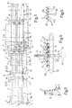
- Number 1 in Figure 1 indicates as a whole a vertical system for cutting and parting sheets 2 of glass to produce flat quadrangular products 3.
- system 1 is equipped to cut and part sheets of laminated glass, i.e. comprising two outer sheets of glass 4, and an intermediate sheet or layer 5 of synthetic material (Figures 3 and 4), and comprises en elongated frame 6 extending in a straight direction A in which sheets 2 are fed during the cutting and parting operations.
- Frame 6 in turn comprises a base 7; and a sloping lateral wall 8 ( Figure 2) extending upwards from base 7 and fitted with a number of known revolving bodies (not shown) defining an inclined lateral supporting surface P for sheets 2.
- a belt conveyor 15 extends between loading station 10 and cutting-parting station 12, close to base 7, and has a feed branch 15a extending parallel to direction A. Sheets 2, positioned on edge on feed branch 15a and resting against surface P, are fed into station 12 and through a cutting-parting assembly 16 at station 12 to cut and part sheets 2, along a number of parallel cutting lines parallel to surface P and perpendicular to direction A, into a number of sheet portions 17.
- assembly 16 comprises two known cutting-parting devices 18 and 19 facing each other on opposite sides of sheet 2 and comprising respective pairs of facing rollers 20 and 21.
- the rollers in each pair are independent, and are powered to rotate about respective axes parallel to surface P and perpendicular to direction A, and to feed sheets 2 and/or sheet portions 17 in direction A on a roller table 22, at least some of the rollers of which are powered.
- Rollers 20, 21 of each device 18, 19 are spaced apart in direction A to define a gap 23, in which a relative known cutting tool 24 runs to cut a relative outer sheet 4 along the relative cutting lines.
- the cut outer sheets 4 are parted in known manner, conveniently by means of parting wheels 25, and intermediate sheet 5 is cut in known manner, conveniently by means of a powered blade cutter (not shown), after first separating the parted sheet portions by means of rollers 20, 21.
- the blade cutter is replaced by a wire 27 held taut between two powered supports on opposite sides of supporting surface P and sheet 2.
- Sheet portions 17 produced at station 12 are fed successively to station 13, traveling parallel to themselves in direction A, first by powered rollers 20, 21 and roller table 22, and then by a belt conveyor 28 located close to base 7 and defining an extension of conveyor 15 on the opposite side of roller table 22.
- conveyor 28 is synchronized with a further conveyor 29 associated with lateral wall 8 and having a feed branch 29a starting from station 12 and coming into station 13.
- Station 13 houses a cutting-parting assembly 30 similar to assembly 16, and the component parts of which are indicated, where possible, using the same reference numbers as for the corresponding parts of assembly 16.
- Assembly 30 is fitted to frame 6 in a position rotated 90° with respect to assembly 16, so that its cutting tools 24, parting wheels 25, and intermediate layer blade cutter run back and forth in a direction A' parallel to direction A, to cut sheet portions 17 along cutting lines L, L1 perpendicular to the cutting lines in station 12.
- cutting tools 24, parting wheels 25, and the blade cutter run along respective known bridges 32 shown schematically in Figure 1 and connected integrally to respective posts 33, in turn connected integrally to frame 6.
- bridges 32 are fitted to respective powered carriages 35 (shown schematically in Figure 1) movable up and down along posts 33 in a direction K parallel to surface P and perpendicular to direction A, to adjust the height of bridges 32 and therefore of the cutting tools, parting wheels, and intermediate layer blade cutter.
- roller table 36 comprising a number of parallel, side by side rollers 37 perpendicular to supporting surface P ( Figures 1 and 5).
- Rollers 37 are powered by a drive 38 ( Figure 5) located at one axial end of rollers 37 and preferably comprising a toothed belt 39 looped about two powered transmission wheels and meshing with a number of pinions 40, each fitted to an end portion of a relative roller 37.
- Station 13 also houses a modular, configurable lift assembly 41 comprising a number of lift members or blocks 42 ( Figure 2) extending parallel to and alternating with rollers 37.
- Each block 42 is carried by a relative slide 43 fitted to run along a relative straight guide 44 connected integrally to frame 6 and parallel to supporting surface P and perpendicular to direction A.
- Lift assembly 41 also comprises, for each block 42, an air-powered jack 45 located at station 13 to move relative block 42, along relative guide 44, to and from a lowered position in which sheet portions 17 rest solely on rollers 37.
- Jacks 45 are controlled independently of one another by a known pneumatic assembly 46, so that, for each sheet portion 17, a respective group of blocks 42, comprising a number of blocks proportional to the dimension of the sheet portion is direction A, is activated.
- all or at least some of jacks 45 move a number of adjacent blocks 42, the slides 43 of which are connected, each time, to the output rod of the relative jack 45 by means of a mechanical selecting device defined, for example, by a connecting plate 43a with holes, which is selectable from a number of different connecting plates, and is connected on one side to the output rod of the jack, and on the other side to the various slides by means of straightforward screws 43b.
- the connecting plate 43a, and therefore the number of blocks 42 to be activated is selected as a function of the size of sheet portions 17 resting on rollers 37.
- rollers 37 form part of an unloading assembly 50 for moving the products 3 produced at station 13 to station 11.
- unloading assembly 50 also comprises a bottom supporting conveyor 51 identical to conveyor 28, and a lateral conveyor 52 identical to conveyor 29.
- sheets 2 to be cut and parted, and resting on conveyor 15 and sloping surface P at station 10 are fed to station 12, where they are first cut and then parted into two or more sheet portions 17.
- Sheet portions 17 are then transferred, parallel to themselves in direction A, from roller table 22 onto conveyor 28, which feeds them successively onto rollers 37 and previously lowered blocks 42 at station 13.
- groups of blocks 42 are formed, depending on the position in direction A and the transverse dimensions of sheet portions 17, and each sheet portion 17, maintained contacting surface P at all times, is raised by the relative group of blocks 42, in a positioning direction K1 parallel to direction K, to a given height, so that the first product 3 produced rests directly on blocks 42.
- sheet portion 17 is cut and parted in known manner by assembly 30 to form the first product 3, which, resting on blocks 42, is eased down, while the rest of the sheet portion is clamped between rollers 20, 21 of assembly 30.
- product 3 On coming to rest on rollers 37, product 3 is released by the relative group of blocks 42 and can therefore be fed to unloading station 11.
- the group of blocks 42 is moved back up into a position close to assembly 30, which, by means of rollers 20, 21, eases the relative sheet portion down onto blocks 42, which are again set to a given height in direction K to produce a second product 3, which is formed and unloaded from station 13 in the same way as described above.
- bridges 32 are also movable in direction K, the movement of blocks 42 is synchronized with the movement of bridges 32 to minimize the travel distance, and therefore time, of both the sheet portion and products with respect to rollers 37.
- system 1 as described therefore requires very little work space both in height and in the feed direction of the sheets, mainly on account of both the sheets and the products produced by cutting and parting the sheets being moved in a straight direction and parallel to themselves at all times.
- the sheets, sheet portions, and finished products are moved at all times substantially on edge, and at any rate resting at all times on respective fixed or translating supports; which conveying method has been found to permit cutting and parting of commonly marketed sheets with a work space of barely 5 metres in height.
- translating the sheets/sheet portions/finished products parallel to themselves and resting at all times on a lateral surface prevents flexing and/or shifting of the sheet portions in the case of thin sheets, and/or accidental impact and handling problems in the case of heavy sheets, thus drastically reducing breakage or chipping of the conveyed plate glass products.
- station 13 by virtue of the structure of station 13 and the way in which the plate glass products are handled in station 13, not only can station 13 house a number of sheet portions, but the sheet portions can be cut and parted simultaneously to produce finished products of the same or even widely differing shape or size. This is due to the presence of independently operated lifting blocks, which can be grouped according to the size of sheet portions 17, thus enabling the sheet portions to be worked independently within the same station, and so increasing the output rate of the system.
- Output rate is further increased when the position of bridges 32 is also adjustable with respect to supporting rollers 37, in that the position of the bridges can be adjusted arbitrarily at any time, even in the presence of sheet portions 17 at station 13, as well as independently of the adjustment of blocks 42.
- system 1 is extremely straightforward and cheap to produce, while at the same time being highly efficient, reliable, and safe.
Landscapes
- Chemical & Material Sciences (AREA)
- Engineering & Computer Science (AREA)
- Materials Engineering (AREA)
- Organic Chemistry (AREA)
- Details Of Cutting Devices (AREA)
- Re-Forming, After-Treatment, Cutting And Transporting Of Glass Products (AREA)
Abstract
Description
Claims (26)
- A method of cutting and parting sheets of glass, the method comprising the steps of setting a sheet (2) to be cut and parted into a substantially vertical or on-edge position; cutting said sheet (2) along at least one first cutting line; parting the sheet along said first cutting line to form at least two side by side sheet portions (17) positioned on edge; transferring the sheet portions (17) to a cutting-parting station (13); and, at the cutting-parting station, cutting each said sheet portion along at least one second cutting line crosswise to said first cutting line, and parting the sheet portion along said second cutting line to form flat products (3); characterized in that said sheet portions (17) are transferred to said cutting-parting station (13) by translating the sheet portions (17) parallel to themselves in a straight feed direction (A); and in that each sheet portion is cut along said second cutting line by imparting to a cutting member (24) at least one travel component in a direction parallel to said straight feed direction (A), after first positioning each sheet portion (17) and the cutting member (24) by translating them with respect to each other in a straight positioning direction (K1) crosswise to said straight feed direction (A).
- A method as claimed in Claim 1, characterized in that the sheet portions (17) and the cutting member (24) are translated with respect to one another in a straight positioning direction (K1) perpendicular to said straight feed direction (A).
- A method as claimed in Claim 1 or 2,
characterized by transferring a number of said sheet portions (17) to said cutting-parting station, and cutting all the sheet portions (17) simultaneously along said second cutting line. - A method as claimed in any one of the foregoing Claims, characterized in that said sheet portions (17) and said cutting member (24) are translated with respect to one another in said straight positioning direction (K1) by maintaining said cutting member (24) in a fixed reference position, and moving each of said sheet portions (17) in said straight positioning direction (K1).
- A method as claimed in any one of Claims 1 to 3, characterized in that each said sheet portion (17) is translated in said straight positioning direction (K1) independently of the other sheet portion (17), and is positioned in at least one desired cutting position with respect to said cutting member (24).
- A method as claimed in Claim 5, characterized in that said sheet portions (17) are moved in said straight positioning direction (K1) by engaging each sheet portion (17) by means of relative lifting means (42), and moving the lifting means (42) up and down in said straight positioning direction (K1).
- A method as claimed in Claim 6, characterized in that said sheet portions (17) are moved in said straight positioning direction (K1) by resting the bottom end of each sheet portion (17) on the relative lifting means (42).
- A method as claimed in any one of the foregoing Claims, characterized in that the flat products (3) formed by cutting and parting said sheet portions (17) are moved successively into a lowered unloading position and unloaded by translating them parallel to themselves in said straight feed direction (A).
- A method as claimed in Claim 7 or 8,
characterized in that said flat products (3) are moved by successively resting said flat products (3) on the respective said lifting means (42), and moving the lifting means (42) to and from said lowered unloading position. - A method as claimed in Claim 9, characterized in that said flat products (3) are rested successively on the respective lifting means by releasably retaining the top flat products (3) as the bottom flat products (3) are unloaded; moving the lifting means (42) back into a loading position beneath the top flat products (3); and lowering the top flat products (3) onto the respective lifting means (42).
- A method as claimed in Claim 10, characterized in that the top flat products are retained by retaining means (20, 21) associated with said cutting member (24).
- A method as claimed in Claim 1, characterized in that translation of the sheet portions (17) with respect to the cutting member (24) in said straight positioning direction (K1) comprises translating the cutting member (24) up and down in said straight positioning direction (K1) into a number of different reference positions.
- A system (1) for cutting and parting sheets of glass, the system comprising supporting means (6) for supporting a sheet (2) to be cut and parted in a substantially vertical or on-edge position; at least one first cutting member (24) for cutting said sheet (2), positioned on edge, along at least one first cutting line; first parting means (25) for parting the sheet along said first cutting line to form at least two side by side sheet portions (17) positioned on edge; conveying means (28, 29) for transferring said sheet portions (17) to a cutting-parting station (13); at least one second cutting member (24), located at said cutting-parting station (13), to cut each said sheet portion (17) along at least one second cutting line; and second parting means (25) for parting the sheet portion (17) along the relative said second cutting line to form flat products (3); characterized in that said conveying means comprise linear conveying means (28, 29) for translating said sheet portions (17), parallel to themselves, in a straight feed direction (A); and by also comprising drive means (18) for driving said second cutting member (24) and imparting to the second cutting member at least one travel component in a direction parallel to said straight feed direction (A); and actuating means (35, 41) for translating the sheet portions (17) and the second cutting member (24) with respect to one another in a straight positioning direction (K1) crosswise to said straight feed direction (A).
- A system as claimed in Claim 13, characterized in that the actuating means translate the sheet portions (17) and the second cutting member (24) with respect to one another in a straight positioning direction (K1) perpendicular to said straight feed direction (A).
- A system as claimed in Claim 14, characterized in that said second cutting member (24) is fitted to a supporting frame (32) to move back and forth parallel to said straight feed direction (A); said supporting frame being positioned in a cutting position, and said actuating means comprising moving means for moving said sheet portions (17) up and down in said straight positioning direction (K1) with respect to said supporting frame.
- A system as claimed in Claim 15, characterized in that said moving means comprise lifting means (43, 45) for engaging said sheet portions (17).
- A system as claimed in Claim 16, characterized in that said lifting means comprise a supporting surface (42) for supporting the bottom ends of said sheet portions (17).
- A system as claimed in Claim 16 or 17,
characterized in that said lifting means comprise, for each said sheet portion (17), a respective powered lifting device movable up and down in said straight positioning direction (K1) independently of the other lifting devices. - A system as claimed in Claim 18, characterized in that each of said lifting devices comprises a respective supporting surface for supporting a bottom edge of the relative said sheet portion (17).
- A system as claimed in Claim 19, characterized in that said supporting surface is configurable as a function of the dimension of the relative said sheet portion (17) measured parallel to said straight feed direction (A).
- A system as claimed in Claim 20, characterized in that each said supporting surface comprises a number of supporting members (42) varying as a function of said dimension of the relative sheet portion (17).
- A system as claimed in Claim 21, characterized in that said supporting members (42) are arranged side by side and parallel, and extend perpendicularly to the straight feed direction (A) and the straight positioning direction (K1).
- A system as claimed in Claim 22, characterized by comprising, for each said supporting member (42), a linear actuator (45) for moving the supporting member (42) up and down in said straight positioning direction (K1); control means (46) being provided to control each said linear actuator (45) independently of the other linear actuators.
- A system as claimed in Claim 23, characterized in that each said lifting device comprises at least one linear actuator, and connecting means (43a) for connecting a variable number of said supporting members (42) to said linear actuator.
- A system as claimed in one of Claims 21 to 24, characterized by comprising a bottom roller table (36) with powered rollers, for supporting said bottom edge of each of said sheet portions (17); said supporting members (42) alternating with the rollers (37) of said roller table (36), and being movable to and from a lowered unloading position, in which said supporting members extend beneath said roller table (36), so that the sheet portions (17) rest solely on said rollers (37).
- A system as claimed in one of Claims 15 to 25, characterized by comprising actuating means (35) for moving said supporting frame (32) up and down in said straight positioning direction (K1) into a number of said cutting positions.
Applications Claiming Priority (2)
| Application Number | Priority Date | Filing Date | Title |
|---|---|---|---|
| ITTO20040158 ITTO20040158A1 (en) | 2004-03-11 | 2004-03-11 | METHOD FOR THE ENGRAVING AND TRUNCATION OF GLASS SLABS AND VERTICAL PLANT FOR THE REALIZATION OF SUCH METHOD |
| ITTO20040158 | 2004-03-11 |
Publications (3)
| Publication Number | Publication Date |
|---|---|
| EP1574484A2 true EP1574484A2 (en) | 2005-09-14 |
| EP1574484A3 EP1574484A3 (en) | 2006-02-01 |
| EP1574484B1 EP1574484B1 (en) | 2014-01-15 |
Family
ID=34814971
Family Applications (1)
| Application Number | Title | Priority Date | Filing Date |
|---|---|---|---|
| EP20050101852 Expired - Lifetime EP1574484B1 (en) | 2004-03-11 | 2005-03-10 | Method of cutting and parting sheets of glass, and vertical apparatus implementing such a method |
Country Status (2)
| Country | Link |
|---|---|
| EP (1) | EP1574484B1 (en) |
| IT (1) | ITTO20040158A1 (en) |
Cited By (2)
| Publication number | Priority date | Publication date | Assignee | Title |
|---|---|---|---|---|
| CN110817435A (en) * | 2019-11-28 | 2020-02-21 | 利辛县天鑫玻璃制品有限公司 | A feeding device for laminated glass processing |
| WO2021034510A1 (en) * | 2019-08-20 | 2021-02-25 | Corning Incorporated | Apparatus and method for cutting glass laminate |
Family Cites Families (4)
| Publication number | Priority date | Publication date | Assignee | Title |
|---|---|---|---|---|
| AT401172B (en) * | 1995-01-24 | 1996-07-25 | Lisec Peter | METHOD FOR DIVIDING GLASS PANELS INTO CUTS |
| IT1288673B1 (en) * | 1996-10-14 | 1998-09-23 | For El Base Di Vianello Fortun | LAMINATED GLASS CUTTING MACHINE |
| JPH11343132A (en) * | 1998-05-29 | 1999-12-14 | Sony Corp | Substrate splitting method |
| IT1318169B1 (en) * | 2000-07-14 | 2003-07-23 | Vilio Luppi | CUTTING MACHINE FOR SLAB MATERIAL, IN PARTICULAR GLASS, CERAMIC, MARBLE, ALUMINUM, STEEL, WOOD AND OTHER MATERIALS |
-
2004
- 2004-03-11 IT ITTO20040158 patent/ITTO20040158A1/en unknown
-
2005
- 2005-03-10 EP EP20050101852 patent/EP1574484B1/en not_active Expired - Lifetime
Cited By (2)
| Publication number | Priority date | Publication date | Assignee | Title |
|---|---|---|---|---|
| WO2021034510A1 (en) * | 2019-08-20 | 2021-02-25 | Corning Incorporated | Apparatus and method for cutting glass laminate |
| CN110817435A (en) * | 2019-11-28 | 2020-02-21 | 利辛县天鑫玻璃制品有限公司 | A feeding device for laminated glass processing |
Also Published As
| Publication number | Publication date |
|---|---|
| ITTO20040158A1 (en) | 2004-06-11 |
| EP1574484B1 (en) | 2014-01-15 |
| EP1574484A3 (en) | 2006-02-01 |
Similar Documents
| Publication | Publication Date | Title |
|---|---|---|
| EP1591427B1 (en) | A workstation for machining plates of glass, marble or the like with an automatic system for loading the plates | |
| CA2645172C (en) | Stamping apparatus with feed device | |
| US4986726A (en) | Plant for automatically stacking and orderly arranging packs of panels of different sizes | |
| KR960006832B1 (en) | Method and device for conveying the workpiece in the cutter | |
| EP1164111B1 (en) | Method of and apparatus for working a glass plate | |
| ITTO20000663A1 (en) | METHOD AND GRINDING MACHINE FOR THE PROCESSING OF GLASS SHEETS. | |
| US6142050A (en) | Cutting machine for elongate workpieces | |
| CZ628090A3 (en) | Process and apparatus for producing flat glass parts | |
| KR101860195B1 (en) | the transfer robot and the transfer system therewith | |
| JP6195035B2 (en) | Glass plate processing equipment | |
| KR20180041682A (en) | Glass plate processing equipment | |
| TWI571421B (en) | Automatic stacking machine and automatic stacking method | |
| US5179883A (en) | Apparatus for dividing wood | |
| EP0314632B1 (en) | Apparatus for handling sheets of glass or other materials and to be used in lines for the cutting and working of said sheets | |
| WO2006057024A1 (en) | Work centre for optimized cutting of materials in the form of slabs | |
| US4413941A (en) | Machine tool support table and feeding device | |
| US4528883A (en) | Apparatus for dividing aerated concrete blocks | |
| EP1574484B1 (en) | Method of cutting and parting sheets of glass, and vertical apparatus implementing such a method | |
| EP0691291B1 (en) | Automatic handling device, particularly for slabs of marble, granite, and other stone materials | |
| IT201900001347A1 (en) | GLANING APPARATUS FOR FLAT SHEETS | |
| EP3810366B1 (en) | A machine for grinding slabs | |
| CN109664365B (en) | A production line for automatic cutting, shaping and trimming of refractory pipes and a production method thereof | |
| US4202228A (en) | Method of cutting slabs from a body of uncured, light-weight concrete and an apparatus for carrying out the method | |
| US3224307A (en) | Method and apparatus for handling sheet materials | |
| KR101733983B1 (en) | High-efficient press system |
Legal Events
| Date | Code | Title | Description |
|---|---|---|---|
| PUAI | Public reference made under article 153(3) epc to a published international application that has entered the european phase |
Free format text: ORIGINAL CODE: 0009012 |
|
| AK | Designated contracting states |
Kind code of ref document: A2 Designated state(s): AT BE BG CH CY CZ DE DK EE ES FI FR GB GR HU IE IS IT LI LT LU MC NL PL PT RO SE SI SK TR |
|
| AX | Request for extension of the european patent |
Extension state: AL BA HR LV MK YU |
|
| PUAL | Search report despatched |
Free format text: ORIGINAL CODE: 0009013 |
|
| AK | Designated contracting states |
Kind code of ref document: A3 Designated state(s): AT BE BG CH CY CZ DE DK EE ES FI FR GB GR HU IE IS IT LI LT LU MC NL PL PT RO SE SI SK TR |
|
| AX | Request for extension of the european patent |
Extension state: AL BA HR LV MK YU |
|
| 17P | Request for examination filed |
Effective date: 20060728 |
|
| AKX | Designation fees paid |
Designated state(s): AT BE BG CH CY CZ DE DK EE ES FI FR GB GR HU IE IS IT LI LT LU MC NL PL PT RO SE SI SK TR |
|
| 17Q | First examination report despatched |
Effective date: 20061129 |
|
| RIC1 | Information provided on ipc code assigned before grant |
Ipc: B65G 49/06 20060101ALI20130416BHEP Ipc: C03B 33/10 20060101ALI20130416BHEP Ipc: B32B 17/10 20060101ALI20130416BHEP Ipc: C03B 33/02 20060101AFI20130416BHEP Ipc: C03B 33/07 20060101ALI20130416BHEP |
|
| GRAP | Despatch of communication of intention to grant a patent |
Free format text: ORIGINAL CODE: EPIDOSNIGR1 |
|
| INTG | Intention to grant announced |
Effective date: 20130527 |
|
| GRAP | Despatch of communication of intention to grant a patent |
Free format text: ORIGINAL CODE: EPIDOSNIGR1 |
|
| INTG | Intention to grant announced |
Effective date: 20130805 |
|
| GRAS | Grant fee paid |
Free format text: ORIGINAL CODE: EPIDOSNIGR3 |
|
| GRAA | (expected) grant |
Free format text: ORIGINAL CODE: 0009210 |
|
| AK | Designated contracting states |
Kind code of ref document: B1 Designated state(s): AT BE BG CH CY CZ DE DK EE ES FI FR GB GR HU IE IS IT LI LT LU MC NL PL PT RO SE SI SK TR |
|
| REG | Reference to a national code |
Ref country code: GB Ref legal event code: FG4D Ref country code: CH Ref legal event code: EP |
|
| REG | Reference to a national code |
Ref country code: AT Ref legal event code: REF Ref document number: 649756 Country of ref document: AT Kind code of ref document: T Effective date: 20140215 |
|
| REG | Reference to a national code |
Ref country code: IE Ref legal event code: FG4D |
|
| REG | Reference to a national code |
Ref country code: DE Ref legal event code: R096 Ref document number: 602005042483 Country of ref document: DE Effective date: 20140227 |
|
| REG | Reference to a national code |
Ref country code: NL Ref legal event code: VDEP Effective date: 20140115 |
|
| REG | Reference to a national code |
Ref country code: AT Ref legal event code: MK05 Ref document number: 649756 Country of ref document: AT Kind code of ref document: T Effective date: 20140115 |
|
| REG | Reference to a national code |
Ref country code: LT Ref legal event code: MG4D |
|
| PG25 | Lapsed in a contracting state [announced via postgrant information from national office to epo] |
Ref country code: IS Free format text: LAPSE BECAUSE OF FAILURE TO SUBMIT A TRANSLATION OF THE DESCRIPTION OR TO PAY THE FEE WITHIN THE PRESCRIBED TIME-LIMIT Effective date: 20140515 Ref country code: LT Free format text: LAPSE BECAUSE OF FAILURE TO SUBMIT A TRANSLATION OF THE DESCRIPTION OR TO PAY THE FEE WITHIN THE PRESCRIBED TIME-LIMIT Effective date: 20140115 |
|
| PG25 | Lapsed in a contracting state [announced via postgrant information from national office to epo] |
Ref country code: SE Free format text: LAPSE BECAUSE OF FAILURE TO SUBMIT A TRANSLATION OF THE DESCRIPTION OR TO PAY THE FEE WITHIN THE PRESCRIBED TIME-LIMIT Effective date: 20140115 Ref country code: AT Free format text: LAPSE BECAUSE OF FAILURE TO SUBMIT A TRANSLATION OF THE DESCRIPTION OR TO PAY THE FEE WITHIN THE PRESCRIBED TIME-LIMIT Effective date: 20140115 Ref country code: NL Free format text: LAPSE BECAUSE OF FAILURE TO SUBMIT A TRANSLATION OF THE DESCRIPTION OR TO PAY THE FEE WITHIN THE PRESCRIBED TIME-LIMIT Effective date: 20140115 Ref country code: CY Free format text: LAPSE BECAUSE OF FAILURE TO SUBMIT A TRANSLATION OF THE DESCRIPTION OR TO PAY THE FEE WITHIN THE PRESCRIBED TIME-LIMIT Effective date: 20140115 Ref country code: ES Free format text: LAPSE BECAUSE OF FAILURE TO SUBMIT A TRANSLATION OF THE DESCRIPTION OR TO PAY THE FEE WITHIN THE PRESCRIBED TIME-LIMIT Effective date: 20140115 Ref country code: FI Free format text: LAPSE BECAUSE OF FAILURE TO SUBMIT A TRANSLATION OF THE DESCRIPTION OR TO PAY THE FEE WITHIN THE PRESCRIBED TIME-LIMIT Effective date: 20140115 Ref country code: PT Free format text: LAPSE BECAUSE OF FAILURE TO SUBMIT A TRANSLATION OF THE DESCRIPTION OR TO PAY THE FEE WITHIN THE PRESCRIBED TIME-LIMIT Effective date: 20140515 |
|
| PG25 | Lapsed in a contracting state [announced via postgrant information from national office to epo] |
Ref country code: BE Free format text: LAPSE BECAUSE OF FAILURE TO SUBMIT A TRANSLATION OF THE DESCRIPTION OR TO PAY THE FEE WITHIN THE PRESCRIBED TIME-LIMIT Effective date: 20140115 |
|
| REG | Reference to a national code |
Ref country code: DE Ref legal event code: R119 Ref document number: 602005042483 Country of ref document: DE |
|
| PG25 | Lapsed in a contracting state [announced via postgrant information from national office to epo] |
Ref country code: RO Free format text: LAPSE BECAUSE OF FAILURE TO SUBMIT A TRANSLATION OF THE DESCRIPTION OR TO PAY THE FEE WITHIN THE PRESCRIBED TIME-LIMIT Effective date: 20140115 Ref country code: CZ Free format text: LAPSE BECAUSE OF FAILURE TO SUBMIT A TRANSLATION OF THE DESCRIPTION OR TO PAY THE FEE WITHIN THE PRESCRIBED TIME-LIMIT Effective date: 20140115 Ref country code: EE Free format text: LAPSE BECAUSE OF FAILURE TO SUBMIT A TRANSLATION OF THE DESCRIPTION OR TO PAY THE FEE WITHIN THE PRESCRIBED TIME-LIMIT Effective date: 20140115 Ref country code: LU Free format text: LAPSE BECAUSE OF FAILURE TO SUBMIT A TRANSLATION OF THE DESCRIPTION OR TO PAY THE FEE WITHIN THE PRESCRIBED TIME-LIMIT Effective date: 20140310 Ref country code: DK Free format text: LAPSE BECAUSE OF FAILURE TO SUBMIT A TRANSLATION OF THE DESCRIPTION OR TO PAY THE FEE WITHIN THE PRESCRIBED TIME-LIMIT Effective date: 20140115 |
|
| REG | Reference to a national code |
Ref country code: CH Ref legal event code: PL |
|
| PLBE | No opposition filed within time limit |
Free format text: ORIGINAL CODE: 0009261 |
|
| STAA | Information on the status of an ep patent application or granted ep patent |
Free format text: STATUS: NO OPPOSITION FILED WITHIN TIME LIMIT |
|
| PG25 | Lapsed in a contracting state [announced via postgrant information from national office to epo] |
Ref country code: PL Free format text: LAPSE BECAUSE OF FAILURE TO SUBMIT A TRANSLATION OF THE DESCRIPTION OR TO PAY THE FEE WITHIN THE PRESCRIBED TIME-LIMIT Effective date: 20140115 Ref country code: SK Free format text: LAPSE BECAUSE OF FAILURE TO SUBMIT A TRANSLATION OF THE DESCRIPTION OR TO PAY THE FEE WITHIN THE PRESCRIBED TIME-LIMIT Effective date: 20140115 |
|
| 26N | No opposition filed |
Effective date: 20141016 |
|
| GBPC | Gb: european patent ceased through non-payment of renewal fee |
Effective date: 20140415 |
|
| REG | Reference to a national code |
Ref country code: FR Ref legal event code: ST Effective date: 20141128 |
|
| REG | Reference to a national code |
Ref country code: IE Ref legal event code: MM4A |
|
| REG | Reference to a national code |
Ref country code: DE Ref legal event code: R119 Ref document number: 602005042483 Country of ref document: DE Effective date: 20141001 |
|
| PG25 | Lapsed in a contracting state [announced via postgrant information from national office to epo] |
Ref country code: CH Free format text: LAPSE BECAUSE OF NON-PAYMENT OF DUE FEES Effective date: 20140331 Ref country code: IE Free format text: LAPSE BECAUSE OF NON-PAYMENT OF DUE FEES Effective date: 20140310 Ref country code: DE Free format text: LAPSE BECAUSE OF NON-PAYMENT OF DUE FEES Effective date: 20141001 Ref country code: GB Free format text: LAPSE BECAUSE OF NON-PAYMENT OF DUE FEES Effective date: 20140415 Ref country code: FR Free format text: LAPSE BECAUSE OF NON-PAYMENT OF DUE FEES Effective date: 20140331 Ref country code: LI Free format text: LAPSE BECAUSE OF NON-PAYMENT OF DUE FEES Effective date: 20140331 |
|
| PG25 | Lapsed in a contracting state [announced via postgrant information from national office to epo] |
Ref country code: SI Free format text: LAPSE BECAUSE OF FAILURE TO SUBMIT A TRANSLATION OF THE DESCRIPTION OR TO PAY THE FEE WITHIN THE PRESCRIBED TIME-LIMIT Effective date: 20140115 |
|
| PG25 | Lapsed in a contracting state [announced via postgrant information from national office to epo] |
Ref country code: BG Free format text: LAPSE BECAUSE OF FAILURE TO SUBMIT A TRANSLATION OF THE DESCRIPTION OR TO PAY THE FEE WITHIN THE PRESCRIBED TIME-LIMIT Effective date: 20140115 Ref country code: MC Free format text: LAPSE BECAUSE OF FAILURE TO SUBMIT A TRANSLATION OF THE DESCRIPTION OR TO PAY THE FEE WITHIN THE PRESCRIBED TIME-LIMIT Effective date: 20140115 |
|
| PG25 | Lapsed in a contracting state [announced via postgrant information from national office to epo] |
Ref country code: GR Free format text: LAPSE BECAUSE OF FAILURE TO SUBMIT A TRANSLATION OF THE DESCRIPTION OR TO PAY THE FEE WITHIN THE PRESCRIBED TIME-LIMIT Effective date: 20140416 Ref country code: IT Free format text: LAPSE BECAUSE OF FAILURE TO SUBMIT A TRANSLATION OF THE DESCRIPTION OR TO PAY THE FEE WITHIN THE PRESCRIBED TIME-LIMIT Effective date: 20140115 |
|
| PG25 | Lapsed in a contracting state [announced via postgrant information from national office to epo] |
Ref country code: HU Free format text: LAPSE BECAUSE OF FAILURE TO SUBMIT A TRANSLATION OF THE DESCRIPTION OR TO PAY THE FEE WITHIN THE PRESCRIBED TIME-LIMIT; INVALID AB INITIO Effective date: 20050310 Ref country code: TR Free format text: LAPSE BECAUSE OF FAILURE TO SUBMIT A TRANSLATION OF THE DESCRIPTION OR TO PAY THE FEE WITHIN THE PRESCRIBED TIME-LIMIT Effective date: 20140115 |