EP1574450A1 - Safety bottle cap - Google Patents
Safety bottle cap Download PDFInfo
- Publication number
- EP1574450A1 EP1574450A1 EP03815431A EP03815431A EP1574450A1 EP 1574450 A1 EP1574450 A1 EP 1574450A1 EP 03815431 A EP03815431 A EP 03815431A EP 03815431 A EP03815431 A EP 03815431A EP 1574450 A1 EP1574450 A1 EP 1574450A1
- Authority
- EP
- European Patent Office
- Prior art keywords
- protrusions
- bottle
- sleeve
- cap
- screw cap
- Prior art date
- Legal status (The legal status is an assumption and is not a legal conclusion. Google has not performed a legal analysis and makes no representation as to the accuracy of the status listed.)
- Granted
Links
- 239000002184 metal Substances 0.000 claims abstract description 9
- 229910052751 metal Inorganic materials 0.000 claims abstract description 9
- 239000007788 liquid Substances 0.000 abstract description 22
- 230000005484 gravity Effects 0.000 description 2
- 238000002347 injection Methods 0.000 description 2
- 239000007924 injection Substances 0.000 description 2
- 239000000243 solution Substances 0.000 description 2
- 239000004698 Polyethylene Substances 0.000 description 1
- 239000004793 Polystyrene Substances 0.000 description 1
- 230000004308 accommodation Effects 0.000 description 1
- 238000013019 agitation Methods 0.000 description 1
- 239000004411 aluminium Substances 0.000 description 1
- 229910052782 aluminium Inorganic materials 0.000 description 1
- XAGFODPZIPBFFR-UHFFFAOYSA-N aluminium Chemical compound [Al] XAGFODPZIPBFFR-UHFFFAOYSA-N 0.000 description 1
- 238000001816 cooling Methods 0.000 description 1
- 230000003247 decreasing effect Effects 0.000 description 1
- 239000011521 glass Substances 0.000 description 1
- 238000004519 manufacturing process Methods 0.000 description 1
- 239000000463 material Substances 0.000 description 1
- 238000003801 milling Methods 0.000 description 1
- 229920003229 poly(methyl methacrylate) Polymers 0.000 description 1
- -1 polyethylene Polymers 0.000 description 1
- 229920000573 polyethylene Polymers 0.000 description 1
- 239000004926 polymethyl methacrylate Substances 0.000 description 1
- 229920002223 polystyrene Polymers 0.000 description 1
- 238000003825 pressing Methods 0.000 description 1
Images
Classifications
-
- B—PERFORMING OPERATIONS; TRANSPORTING
- B65—CONVEYING; PACKING; STORING; HANDLING THIN OR FILAMENTARY MATERIAL
- B65D—CONTAINERS FOR STORAGE OR TRANSPORT OF ARTICLES OR MATERIALS, e.g. BAGS, BARRELS, BOTTLES, BOXES, CANS, CARTONS, CRATES, DRUMS, JARS, TANKS, HOPPERS, FORWARDING CONTAINERS; ACCESSORIES, CLOSURES, OR FITTINGS THEREFOR; PACKAGING ELEMENTS; PACKAGES
- B65D49/00—Arrangements or devices for preventing refilling of containers
- B65D49/02—One-way valves
-
- B—PERFORMING OPERATIONS; TRANSPORTING
- B65—CONVEYING; PACKING; STORING; HANDLING THIN OR FILAMENTARY MATERIAL
- B65D—CONTAINERS FOR STORAGE OR TRANSPORT OF ARTICLES OR MATERIALS, e.g. BAGS, BARRELS, BOTTLES, BOXES, CANS, CARTONS, CRATES, DRUMS, JARS, TANKS, HOPPERS, FORWARDING CONTAINERS; ACCESSORIES, CLOSURES, OR FITTINGS THEREFOR; PACKAGING ELEMENTS; PACKAGES
- B65D41/00—Caps, e.g. crown caps or crown seals, i.e. members having parts arranged for engagement with the external periphery of a neck or wall defining a pouring opening or discharge aperture; Protective cap-like covers for closure members, e.g. decorative covers of metal foil or paper
- B65D41/62—Secondary protective cap-like outer covers for closure members
Definitions
- the invention relates to closing devices for low-viscosity liquid containers preventing refilling thereof during storage and transportation.
- a closing device is known for bottles described in application EP 0670271, A1 IPC 6 B 65 D 49/00, published in 1995, which comprises a case of a cylindrical shape at the bottom end of which there is provided a seat with a through-pass opening supporting the gate element.
- the inner surface of the case is adjoined tightly by a splitter in the form of a ring with ribs dividing the interior space of the case into through-pass channels for liquid flow.
- the device is resiliently and sealingly fixed inside the bottleneck using elastic annular protrusions which prevent leaking of the liquid.
- the disclosed device however, has a number of essential drawbacks affecting its functional operation.
- the ball-shaped gate element is unstable, which dictates the shape of upright guides for accommodation on the seat, these guides being positioned such that the ball is squeezed there between due to which its mobility is limited.
- pressure reduction in the bottle occurs which may result in sticking of the gate element and in failure to pour out the liquid, which requires quick agitation of the container.
- a closing device contains a cylindrical sleeve the upper portion of which is a screw cap and has a moveable elastic annular protrusion to be fixed on a bottle, thereby providing a permanent connection.
- a cowl with a warranty collar is pressed on the screw cap, a splitter in the form of a ribbed ring is positioned inside the housing by means of a thread, the ribs dividing the interior space into through-pass channels for liquid flow.
- the housing cavity is provided with a resilient element having on its centre a seat with a through-pass opening which supports the gate element in the form of a valve.
- the resilient element is sealingly fixed inside the bottleneck using the elastic annular protrusions and is hermetically connected to the housing for pouring in the liquid, which prevents leaking out the liquid.
- This device has a number of essential drawbacks affecting its functional operation. Because of the presence of the moveable valve, its deformation and wedging are possible as well as sticking at a decreased temperature due to reduced pressure within the container, which results in failure to pour out the liquid and in the need to agitate the container so that the valve could operate.
- the closest technical solution to the present invention is a safety bottle cap comprising a metal enclosure with a screw cap fastened by a thread on an outer sleeve connected by ribs to an internal sleeve and forming through-pass channels, a resilient element with a put-trough-pass opening and protrusions that form an open-top annular cavity containing a low part of the internal sleeve, thereby forming a gap between the bottom and protrusions of the resilient element.
- RU No.2193000, Cl. B 65 D 49/02, published 20.11.2002.
- the proposed technical solution is directed to improvement of reliability thereof by using an additional level of protection against bottle refilling.
- the safety bottle cap comprises a metal enclosure with a screw cap which is fixed to an external sleeve with the aid of a thread; said external sleeve is connected to an internal sleeve by means of ribs in such a way that through channels are formed; the safety cap also comprises an elastic element provided with a through-pass holes and protrusions which form an annular open-top cavity containing the low part of the internal sleeve, thereby forming a space between the bottom and protrusions of the elastic element; there is a metal enclosure which is fixed to the screw cap which is provided with a control indicator collar; said metal enclosure is provided in the form of two adjacent parts the edges of which are seamed, thereby forming the control indicator collar in such way that one of the edges is released when the cap is unscrewed.
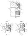
- Fig.1 schematically shows the safety cap in sectional view
- Fig.2 shows assembly A of Fig.1, the cap before opening
- Fig.3 shows the same, the cap after opening.
- Screw cap 2 is made with a control indicator collar 3 along the outline of the low part of the screw cap, the edges of the enclosure 1 are seamed into the control indicator collar 3.
- Cap 2 is fixed by a thread to external sleeve 4 connected by ribs 5 with internal sleeve 6, thereby forming through channels 7.
- Low part of interior sleeve 6 with a closed upper end is positioned adjacent to elastic element 8 having through hole 9 and protrusions 10 and 11 forming an open-top cavity 12.
- the low part of interior sleeve 6 is located within annular cavity 12, thereby to form a space between bottom 13, protrusions 10 and 11 of elastic element 8, which provides a hydraulic lock.
- the device operates as follows.
- the liquid present in through channels 7 is enters to the annular cavity of the hydraulic lock and further to the bottle, thereby providing excessive pressure preventing further inflow of the liquid.
- the pressure created by the hydraulic lock within the container prevents the liquid from filling the container.
- the safety bottle cap preventing refilling the container, with the hydraulic lock, assembled from4 parts and having several standard heights, suits a wide range of bottle shapes.
- the control safety collar and hydraulic lock provide a high level of protection from refilling.
- the bottle closure is effected by pressing from the top downwards using a closing machine (not shown).
- All parts of the safety bottle cap are made of environmentally pure materials, polyethylene, polystyrene and metal on high-capacity automatic injection machines by injection using moulds with a hot runner system and dies.
- a pilot specimen of the hydraulic lock valve was manufactured at the pilot/mechanical production facility IUPP AO "BELCAPS" on a lathe and milling equipment.
- the external sleeve was made of polymethylmethacrylate (organic glass), the elastic element was made of caprolon, and the enclosure was made of an aluminium sheet.
Landscapes
- Engineering & Computer Science (AREA)
- Mechanical Engineering (AREA)
- Closures For Containers (AREA)
- Emergency Lowering Means (AREA)
- Road Signs Or Road Markings (AREA)
- Nitrogen And Oxygen Or Sulfur-Condensed Heterocyclic Ring Systems (AREA)
Abstract
Description
Claims (1)
- A safety bottle cap comprising a screw cap which is fixed to an external sleeve with the aid of a thread; said external sleeve is connected to an internal sleeve by means of ribs in such a way that through channels are formed; the safety cap also comprising an elastic element provided with through holes and protrusions which form an annular open-top cavity containing the low part of the internal sleeve, thereby forming a space between the bottom and protrusions of the elastic element, characterised in that it is provided with a metal enclosure which is fixed to the screw cap the latter being provided on the outline with a control indicator collar; said metal enclosure being provided in the form of two adjacent parts the edges of which are seamed, thereby forming the control indicator collar in such way that one of the edges is released when the cap is unscrewed.
Applications Claiming Priority (3)
| Application Number | Priority Date | Filing Date | Title |
|---|---|---|---|
| RU2003101273/12A RU2225337C1 (en) | 2003-01-17 | 2003-01-17 | Bottle safety cap |
| RU2003101273 | 2003-01-17 | ||
| PCT/IB2003/006440 WO2004065248A1 (en) | 2003-01-17 | 2003-12-02 | Safety bottle cap |
Publications (3)
| Publication Number | Publication Date |
|---|---|
| EP1574450A1 true EP1574450A1 (en) | 2005-09-14 |
| EP1574450A4 EP1574450A4 (en) | 2006-08-02 |
| EP1574450B1 EP1574450B1 (en) | 2009-07-01 |
Family
ID=32390806
Family Applications (1)
| Application Number | Title | Priority Date | Filing Date |
|---|---|---|---|
| EP03815431A Expired - Lifetime EP1574450B1 (en) | 2003-01-17 | 2003-12-02 | Safety bottle cap |
Country Status (7)
| Country | Link |
|---|---|
| EP (1) | EP1574450B1 (en) |
| AT (1) | ATE435169T1 (en) |
| AU (1) | AU2003300684A1 (en) |
| DE (2) | DE03815431T1 (en) |
| RU (1) | RU2225337C1 (en) |
| UA (1) | UA74270C2 (en) |
| WO (1) | WO2004065248A1 (en) |
Cited By (5)
| Publication number | Priority date | Publication date | Assignee | Title |
|---|---|---|---|---|
| EP1950144A1 (en) * | 2007-01-25 | 2008-07-30 | Inostrannoye Chastnoe Proizvodstvennoye Unitarnoye Predpriyatiye "Belkeps" | Closure |
| WO2009095851A1 (en) * | 2008-01-31 | 2009-08-06 | Alplast S.P.A. | A security closure assembly for a container, in particular for a bottle for liquids |
| BG1202U1 (en) * | 2008-06-24 | 2009-08-31 | "Артемис" Оод | Safety cap for bottles with aluminum wrap |
| EP1927553A4 (en) * | 2005-09-21 | 2009-11-04 | Dmitriy Ivanovitch Pachomov | Combination of a safety lid and container |
| EA012762B1 (en) * | 2008-03-28 | 2009-12-30 | Дмитрий Иванович ПАХОМОВ | Closure with extensible tamper evident means |
Families Citing this family (17)
| Publication number | Priority date | Publication date | Assignee | Title |
|---|---|---|---|---|
| UA5859U (en) * | 2004-08-09 | 2005-03-15 | Общєство С Огранічєнной Отвєтствєнностью Торговий Дом "Альтернатіва-Ана" | Plug for bottle |
| ES2229959B1 (en) * | 2004-12-24 | 2006-02-16 | Plastivit, S.A. | IRRELLENABLE PLUG WITH DOUBLE SECURITY DEVICE. |
| RU2296702C1 (en) * | 2005-08-30 | 2007-04-10 | Иностранное Унитарное Производственное Предприятие Компании "Белкапс Бетайлингус Гмбх" Белкэпс | Safety cover-and-container combination |
| EA008470B1 (en) * | 2005-09-21 | 2007-06-29 | Дмитрий Иванович ПАХОМОВ | Closure cap with tamper evident means |
| ITMI20060247A1 (en) * | 2006-02-10 | 2007-08-11 | Nicola Fabiano | CLOSING DEVICE FOR BOTTLES AND OPARTYICULAR FOR BOTTLES OF ALCOHOLIC AND SUPERCHOLICS |
| RU2373123C2 (en) * | 2006-11-16 | 2009-11-20 | Роман Григорьевич Беккер | Polymer cap with button (versions) |
| WO2008108675A1 (en) * | 2007-03-07 | 2008-09-12 | Obshestvo S Ogranichennoi Otvetstvennostiu 'meridian' | Bottle closing device with an extending pipe |
| EA011751B1 (en) | 2007-06-18 | 2009-06-30 | Дмитрий Иванович ПАХОМОВ | Closure device |
| WO2009011672A1 (en) * | 2007-07-18 | 2009-01-22 | Aleksejs Leonidovich Zabello | Closing device with first opening indication |
| CN201151512Y (en) * | 2007-07-19 | 2008-11-19 | 格乐杰投资有限公司 | Cover for liquid container |
| EA016393B1 (en) * | 2010-05-17 | 2012-04-30 | Дмитрий Иванович ПАХОМОВ | Safety bottle cap |
| SI2444334T1 (en) * | 2010-09-28 | 2014-03-31 | Cedc International Sp. Z.O.O. | Safety bottle cap |
| RU2450066C1 (en) * | 2011-03-11 | 2012-05-10 | Виктор Григорьевич Оголь | Method to process nepheline ores to produce alumina and soda products |
| CN102633043A (en) * | 2012-04-19 | 2012-08-15 | 孙德善 | Soy bottle cap |
| RU191981U1 (en) * | 2019-04-18 | 2019-08-29 | Производственное унитарное предприятие "АЛКОПАК" | CAP FOR BOTTLE |
| RU194088U1 (en) * | 2019-07-08 | 2019-11-28 | Производственное унитарное предприятие "АЛКОПАК" | OPENING INDICATOR FOR CUTTER DEVICE |
| RU206885U1 (en) * | 2021-03-15 | 2021-09-30 | Дмитрий Иванович Пахомов | CONTAINER SEALING CAP |
Family Cites Families (5)
| Publication number | Priority date | Publication date | Assignee | Title |
|---|---|---|---|---|
| IT1273362B (en) * | 1994-03-02 | 1997-07-08 | Alucapvit Spa | BOTTLE CLOSING DEVICE WITH GUARANTEE SEAL AND ANTI-FILL VALVE |
| IT1275779B1 (en) * | 1995-07-06 | 1997-10-17 | Guala Spa | CLOSURE OF GUARANTEE FOR BOTTLES FOR VALUABLE LIQUORS |
| FR2793216B1 (en) * | 1999-04-20 | 2001-06-08 | Pechiney Emballage Alimentaire | COMPOSITE CAPPING CAPSULE |
| RU2193000C1 (en) * | 2001-04-18 | 2002-11-20 | Иностранное производственное унитарное предприятие акционерного общества "Мультипак" | Protective cap |
| GB0112726D0 (en) * | 2001-05-25 | 2001-07-18 | Montgomery Daniel & Son Ltd | Tamper-evident device |
-
2003
- 2003-01-17 RU RU2003101273/12A patent/RU2225337C1/en active IP Right Revival
- 2003-12-02 WO PCT/IB2003/006440 patent/WO2004065248A1/en not_active Ceased
- 2003-12-02 EP EP03815431A patent/EP1574450B1/en not_active Expired - Lifetime
- 2003-12-02 AU AU2003300684A patent/AU2003300684A1/en not_active Abandoned
- 2003-12-02 DE DE03815431T patent/DE03815431T1/en active Pending
- 2003-12-02 AT AT03815431T patent/ATE435169T1/en not_active IP Right Cessation
- 2003-12-02 DE DE60328221T patent/DE60328221D1/en not_active Expired - Lifetime
- 2003-12-29 UA UA20031212889A patent/UA74270C2/en unknown
Cited By (7)
| Publication number | Priority date | Publication date | Assignee | Title |
|---|---|---|---|---|
| EP1927553A4 (en) * | 2005-09-21 | 2009-11-04 | Dmitriy Ivanovitch Pachomov | Combination of a safety lid and container |
| EP1950144A1 (en) * | 2007-01-25 | 2008-07-30 | Inostrannoye Chastnoe Proizvodstvennoye Unitarnoye Predpriyatiye "Belkeps" | Closure |
| WO2009095851A1 (en) * | 2008-01-31 | 2009-08-06 | Alplast S.P.A. | A security closure assembly for a container, in particular for a bottle for liquids |
| US8439213B2 (en) | 2008-01-31 | 2013-05-14 | Alplast S.P.A. | Security closure assembly for a container, in particular for a bottle for liquids |
| EA018520B1 (en) * | 2008-01-31 | 2013-08-30 | Альпласт С.П.А. | Security closure assembly for a container, in particular for a bottle for liquids |
| EA012762B1 (en) * | 2008-03-28 | 2009-12-30 | Дмитрий Иванович ПАХОМОВ | Closure with extensible tamper evident means |
| BG1202U1 (en) * | 2008-06-24 | 2009-08-31 | "Артемис" Оод | Safety cap for bottles with aluminum wrap |
Also Published As
| Publication number | Publication date |
|---|---|
| RU2225337C1 (en) | 2004-03-10 |
| EP1574450B1 (en) | 2009-07-01 |
| EP1574450A4 (en) | 2006-08-02 |
| UA74270C2 (en) | 2005-11-15 |
| DE03815431T1 (en) | 2006-11-30 |
| WO2004065248A1 (en) | 2004-08-05 |
| DE60328221D1 (en) | 2009-08-13 |
| AU2003300684A1 (en) | 2004-08-13 |
| ATE435169T1 (en) | 2009-07-15 |
Similar Documents
| Publication | Publication Date | Title |
|---|---|---|
| EP1574450B1 (en) | Safety bottle cap | |
| US5020692A (en) | Container including unitary blow molded bottle having drain-back dispensing spout and plastic insert | |
| US3147876A (en) | Containers having caps permitting pressure equalization of contents of container | |
| JPH09292040A (en) | Large cutoff cock device mounted on pallet container | |
| US2298655A (en) | Dispensing closure | |
| WO2006114106A1 (en) | Bottle closing device | |
| KR101122274B1 (en) | Vessel for hair dye with hydrogen peroxide | |
| CN201099438Y (en) | Top opening type double layer sealed, three-member type plastic anti-conterfeit bottle cap | |
| JPH08198295A (en) | Foamed liquid squeeze container | |
| RU2296702C1 (en) | Safety cover-and-container combination | |
| US5829638A (en) | Contact opening cap for bottle containers | |
| JP7334625B2 (en) | pouring container | |
| RU2148544C1 (en) | Plug | |
| RU205329U1 (en) | CONTAINER CLOSER | |
| JP7189692B2 (en) | Double container and its manufacturing method | |
| US2472950A (en) | Nonrefillable bottle | |
| RU159335U1 (en) | COTTING DEVICE FOR BOTTLE | |
| JP2024103825A (en) | Cap and processing method for said cap | |
| RU81705U1 (en) | CAPACITY SAFETY LOCK | |
| JP2023111393A (en) | Spout cap | |
| EP1927553B1 (en) | Combination of a safety lid and container | |
| US2590949A (en) | Bottle closure | |
| KR0115266Y1 (en) | Funnel for oil | |
| US2200761A (en) | Device for preventing the refilling of bottles and the like | |
| KR950008376Y1 (en) | Dispensing unit for bottled water |
Legal Events
| Date | Code | Title | Description |
|---|---|---|---|
| PUAI | Public reference made under article 153(3) epc to a published international application that has entered the european phase |
Free format text: ORIGINAL CODE: 0009012 |
|
| 17P | Request for examination filed |
Effective date: 20050620 |
|
| AK | Designated contracting states |
Kind code of ref document: A1 Designated state(s): AT BE BG CH CY CZ DE DK EE ES FI FR GB GR HU IE IT LI LU MC NL PT RO SE SI SK TR |
|
| AX | Request for extension of the european patent |
Extension state: AL LT LV MK |
|
| RAX | Requested extension states of the european patent have changed |
Extension state: LV Payment date: 20050620 Extension state: MK Payment date: 20050620 |
|
| A4 | Supplementary search report drawn up and despatched |
Effective date: 20060703 |
|
| REG | Reference to a national code |
Ref country code: GR Ref legal event code: PP Ref document number: 20060300016 Country of ref document: GR |
|
| 17Q | First examination report despatched |
Effective date: 20060928 |
|
| DET | De: translation of patent claims | ||
| RAP1 | Party data changed (applicant data changed or rights of an application transferred) |
Owner name: INOSTRANNOYE CHASTNOE PROIZVODSTVENNOYE UNITARNOYE |
|
| GRAP | Despatch of communication of intention to grant a patent |
Free format text: ORIGINAL CODE: EPIDOSNIGR1 |
|
| GRAS | Grant fee paid |
Free format text: ORIGINAL CODE: EPIDOSNIGR3 |
|
| GRAA | (expected) grant |
Free format text: ORIGINAL CODE: 0009210 |
|
| AK | Designated contracting states |
Kind code of ref document: B1 Designated state(s): AT BE BG CH CY CZ DE DK EE ES FI FR GB GR HU IE IT LI LU MC NL PT RO SE SI SK TR |
|
| AX | Request for extension of the european patent |
Extension state: LV MK |
|
| REG | Reference to a national code |
Ref country code: GB Ref legal event code: FG4D |
|
| REG | Reference to a national code |
Ref country code: CH Ref legal event code: EP |
|
| REG | Reference to a national code |
Ref country code: IE Ref legal event code: FG4D |
|
| REF | Corresponds to: |
Ref document number: 60328221 Country of ref document: DE Date of ref document: 20090813 Kind code of ref document: P |
|
| PG25 | Lapsed in a contracting state [announced via postgrant information from national office to epo] |
Ref country code: SI Free format text: LAPSE BECAUSE OF FAILURE TO SUBMIT A TRANSLATION OF THE DESCRIPTION OR TO PAY THE FEE WITHIN THE PRESCRIBED TIME-LIMIT Effective date: 20090701 |
|
| NLV1 | Nl: lapsed or annulled due to failure to fulfill the requirements of art. 29p and 29m of the patents act | ||
| PG25 | Lapsed in a contracting state [announced via postgrant information from national office to epo] |
Ref country code: SE Free format text: LAPSE BECAUSE OF FAILURE TO SUBMIT A TRANSLATION OF THE DESCRIPTION OR TO PAY THE FEE WITHIN THE PRESCRIBED TIME-LIMIT Effective date: 20090701 Ref country code: AT Free format text: LAPSE BECAUSE OF FAILURE TO SUBMIT A TRANSLATION OF THE DESCRIPTION OR TO PAY THE FEE WITHIN THE PRESCRIBED TIME-LIMIT Effective date: 20090701 Ref country code: EE Free format text: LAPSE BECAUSE OF FAILURE TO SUBMIT A TRANSLATION OF THE DESCRIPTION OR TO PAY THE FEE WITHIN THE PRESCRIBED TIME-LIMIT Effective date: 20090701 Ref country code: ES Free format text: LAPSE BECAUSE OF FAILURE TO SUBMIT A TRANSLATION OF THE DESCRIPTION OR TO PAY THE FEE WITHIN THE PRESCRIBED TIME-LIMIT Effective date: 20091012 Ref country code: FI Free format text: LAPSE BECAUSE OF FAILURE TO SUBMIT A TRANSLATION OF THE DESCRIPTION OR TO PAY THE FEE WITHIN THE PRESCRIBED TIME-LIMIT Effective date: 20090701 |
|
| PG25 | Lapsed in a contracting state [announced via postgrant information from national office to epo] |
Ref country code: NL Free format text: LAPSE BECAUSE OF FAILURE TO SUBMIT A TRANSLATION OF THE DESCRIPTION OR TO PAY THE FEE WITHIN THE PRESCRIBED TIME-LIMIT Effective date: 20090701 |
|
| PG25 | Lapsed in a contracting state [announced via postgrant information from national office to epo] |
Ref country code: BG Free format text: LAPSE BECAUSE OF FAILURE TO SUBMIT A TRANSLATION OF THE DESCRIPTION OR TO PAY THE FEE WITHIN THE PRESCRIBED TIME-LIMIT Effective date: 20091001 Ref country code: PT Free format text: LAPSE BECAUSE OF FAILURE TO SUBMIT A TRANSLATION OF THE DESCRIPTION OR TO PAY THE FEE WITHIN THE PRESCRIBED TIME-LIMIT Effective date: 20091102 |
|
| PLBI | Opposition filed |
Free format text: ORIGINAL CODE: 0009260 |
|
| PG25 | Lapsed in a contracting state [announced via postgrant information from national office to epo] |
Ref country code: DK Free format text: LAPSE BECAUSE OF FAILURE TO SUBMIT A TRANSLATION OF THE DESCRIPTION OR TO PAY THE FEE WITHIN THE PRESCRIBED TIME-LIMIT Effective date: 20090701 Ref country code: RO Free format text: LAPSE BECAUSE OF FAILURE TO SUBMIT A TRANSLATION OF THE DESCRIPTION OR TO PAY THE FEE WITHIN THE PRESCRIBED TIME-LIMIT Effective date: 20090701 Ref country code: CZ Free format text: LAPSE BECAUSE OF FAILURE TO SUBMIT A TRANSLATION OF THE DESCRIPTION OR TO PAY THE FEE WITHIN THE PRESCRIBED TIME-LIMIT Effective date: 20090701 |
|
| PLAX | Notice of opposition and request to file observation + time limit sent |
Free format text: ORIGINAL CODE: EPIDOSNOBS2 |
|
| 26 | Opposition filed |
Opponent name: GUALA CLOSURES S.P.A./ GUALA CLOSURES PATENTS B.V. Effective date: 20100329 |
|
| PG25 | Lapsed in a contracting state [announced via postgrant information from national office to epo] |
Ref country code: SK Free format text: LAPSE BECAUSE OF FAILURE TO SUBMIT A TRANSLATION OF THE DESCRIPTION OR TO PAY THE FEE WITHIN THE PRESCRIBED TIME-LIMIT Effective date: 20090701 Ref country code: BE Free format text: LAPSE BECAUSE OF FAILURE TO SUBMIT A TRANSLATION OF THE DESCRIPTION OR TO PAY THE FEE WITHIN THE PRESCRIBED TIME-LIMIT Effective date: 20090701 |
|
| PG25 | Lapsed in a contracting state [announced via postgrant information from national office to epo] |
Ref country code: MC Free format text: LAPSE BECAUSE OF NON-PAYMENT OF DUE FEES Effective date: 20100701 |
|
| REG | Reference to a national code |
Ref country code: CH Ref legal event code: PL |
|
| PLBB | Reply of patent proprietor to notice(s) of opposition received |
Free format text: ORIGINAL CODE: EPIDOSNOBS3 |
|
| PG25 | Lapsed in a contracting state [announced via postgrant information from national office to epo] |
Ref country code: LI Free format text: LAPSE BECAUSE OF NON-PAYMENT OF DUE FEES Effective date: 20091231 Ref country code: IE Free format text: LAPSE BECAUSE OF NON-PAYMENT OF DUE FEES Effective date: 20091202 Ref country code: GR Free format text: LAPSE BECAUSE OF FAILURE TO SUBMIT A TRANSLATION OF THE DESCRIPTION OR TO PAY THE FEE WITHIN THE PRESCRIBED TIME-LIMIT Effective date: 20091002 Ref country code: CH Free format text: LAPSE BECAUSE OF NON-PAYMENT OF DUE FEES Effective date: 20091231 |
|
| PLAY | Examination report in opposition despatched + time limit |
Free format text: ORIGINAL CODE: EPIDOSNORE2 |
|
| PG25 | Lapsed in a contracting state [announced via postgrant information from national office to epo] |
Ref country code: IT Free format text: LAPSE BECAUSE OF FAILURE TO SUBMIT A TRANSLATION OF THE DESCRIPTION OR TO PAY THE FEE WITHIN THE PRESCRIBED TIME-LIMIT Effective date: 20090701 |
|
| PG25 | Lapsed in a contracting state [announced via postgrant information from national office to epo] |
Ref country code: LU Free format text: LAPSE BECAUSE OF NON-PAYMENT OF DUE FEES Effective date: 20091202 |
|
| PG25 | Lapsed in a contracting state [announced via postgrant information from national office to epo] |
Ref country code: HU Free format text: LAPSE BECAUSE OF FAILURE TO SUBMIT A TRANSLATION OF THE DESCRIPTION OR TO PAY THE FEE WITHIN THE PRESCRIBED TIME-LIMIT Effective date: 20100102 |
|
| PLBC | Reply to examination report in opposition received |
Free format text: ORIGINAL CODE: EPIDOSNORE3 |
|
| PG25 | Lapsed in a contracting state [announced via postgrant information from national office to epo] |
Ref country code: TR Free format text: LAPSE BECAUSE OF FAILURE TO SUBMIT A TRANSLATION OF THE DESCRIPTION OR TO PAY THE FEE WITHIN THE PRESCRIBED TIME-LIMIT Effective date: 20090701 |
|
| PLAY | Examination report in opposition despatched + time limit |
Free format text: ORIGINAL CODE: EPIDOSNORE2 |
|
| PG25 | Lapsed in a contracting state [announced via postgrant information from national office to epo] |
Ref country code: CY Free format text: LAPSE BECAUSE OF FAILURE TO SUBMIT A TRANSLATION OF THE DESCRIPTION OR TO PAY THE FEE WITHIN THE PRESCRIBED TIME-LIMIT Effective date: 20090701 |
|
| PLAH | Information related to despatch of examination report in opposition + time limit modified |
Free format text: ORIGINAL CODE: EPIDOSCORE2 |
|
| PLAH | Information related to despatch of examination report in opposition + time limit modified |
Free format text: ORIGINAL CODE: EPIDOSCORE2 |
|
| PLAB | Opposition data, opponent's data or that of the opponent's representative modified |
Free format text: ORIGINAL CODE: 0009299OPPO |
|
| PLBC | Reply to examination report in opposition received |
Free format text: ORIGINAL CODE: EPIDOSNORE3 |
|
| R26 | Opposition filed (corrected) |
Opponent name: GUALA CLOSURES S.P.A./ GUALA CLOSURES PATENTS B.V. Effective date: 20100329 |
|
| PLCK | Communication despatched that opposition was rejected |
Free format text: ORIGINAL CODE: EPIDOSNREJ1 |
|
| PLBN | Opposition rejected |
Free format text: ORIGINAL CODE: 0009273 |
|
| STAA | Information on the status of an ep patent application or granted ep patent |
Free format text: STATUS: OPPOSITION REJECTED |
|
| 27O | Opposition rejected |
Effective date: 20121210 |
|
| REG | Reference to a national code |
Ref country code: DE Ref legal event code: R100 Ref document number: 60328221 Country of ref document: DE Effective date: 20121210 |
|
| REG | Reference to a national code |
Ref country code: FR Ref legal event code: PLFP Year of fee payment: 13 |
|
| PGFP | Annual fee paid to national office [announced via postgrant information from national office to epo] |
Ref country code: GB Payment date: 20151223 Year of fee payment: 13 |
|
| PGFP | Annual fee paid to national office [announced via postgrant information from national office to epo] |
Ref country code: DE Payment date: 20151223 Year of fee payment: 13 |
|
| PGFP | Annual fee paid to national office [announced via postgrant information from national office to epo] |
Ref country code: FR Payment date: 20151223 Year of fee payment: 13 |
|
| REG | Reference to a national code |
Ref country code: DE Ref legal event code: R119 Ref document number: 60328221 Country of ref document: DE |
|
| GBPC | Gb: european patent ceased through non-payment of renewal fee |
Effective date: 20161202 |
|
| REG | Reference to a national code |
Ref country code: FR Ref legal event code: ST Effective date: 20170831 |
|
| PG25 | Lapsed in a contracting state [announced via postgrant information from national office to epo] |
Ref country code: FR Free format text: LAPSE BECAUSE OF NON-PAYMENT OF DUE FEES Effective date: 20170102 |
|
| PG25 | Lapsed in a contracting state [announced via postgrant information from national office to epo] |
Ref country code: GB Free format text: LAPSE BECAUSE OF NON-PAYMENT OF DUE FEES Effective date: 20161202 Ref country code: DE Free format text: LAPSE BECAUSE OF NON-PAYMENT OF DUE FEES Effective date: 20170701 |