EP1574415A1 - Lenkungseinheit für ein elektrisches Fahrzeug - Google Patents
Lenkungseinheit für ein elektrisches Fahrzeug Download PDFInfo
- Publication number
- EP1574415A1 EP1574415A1 EP04425161A EP04425161A EP1574415A1 EP 1574415 A1 EP1574415 A1 EP 1574415A1 EP 04425161 A EP04425161 A EP 04425161A EP 04425161 A EP04425161 A EP 04425161A EP 1574415 A1 EP1574415 A1 EP 1574415A1
- Authority
- EP
- European Patent Office
- Prior art keywords
- output shaft
- steering unit
- steering
- axis
- rod
- Prior art date
- Legal status (The legal status is an assumption and is not a legal conclusion. Google has not performed a legal analysis and makes no representation as to the accuracy of the status listed.)
- Granted
Links
- 230000008878 coupling Effects 0.000 claims abstract description 11
- 238000010168 coupling process Methods 0.000 claims abstract description 11
- 238000005859 coupling reaction Methods 0.000 claims abstract description 11
- 230000005355 Hall effect Effects 0.000 claims description 2
- 230000003134 recirculating effect Effects 0.000 claims description 2
- 239000003795 chemical substances by application Substances 0.000 description 1
- 230000001010 compromised effect Effects 0.000 description 1
- 238000006073 displacement reaction Methods 0.000 description 1
- 239000000428 dust Substances 0.000 description 1
- 230000005611 electricity Effects 0.000 description 1
- 238000005461 lubrication Methods 0.000 description 1
- 238000005096 rolling process Methods 0.000 description 1
Images

Classifications
-
- B—PERFORMING OPERATIONS; TRANSPORTING
- B62—LAND VEHICLES FOR TRAVELLING OTHERWISE THAN ON RAILS
- B62D—MOTOR VEHICLES; TRAILERS
- B62D5/00—Power-assisted or power-driven steering
- B62D5/04—Power-assisted or power-driven steering electrical, e.g. using an electric servo-motor connected to, or forming part of, the steering gear
- B62D5/0421—Electric motor acting on or near steering gear
- B62D5/0424—Electric motor acting on or near steering gear the axes of motor and final driven element of steering gear, e.g. rack, being parallel
- B62D5/0427—Electric motor acting on or near steering gear the axes of motor and final driven element of steering gear, e.g. rack, being parallel the axes being coaxial
-
- B—PERFORMING OPERATIONS; TRANSPORTING
- B62—LAND VEHICLES FOR TRAVELLING OTHERWISE THAN ON RAILS
- B62D—MOTOR VEHICLES; TRAILERS
- B62D15/00—Steering not otherwise provided for
- B62D15/02—Steering position indicators ; Steering position determination; Steering aids
- B62D15/021—Determination of steering angle
- B62D15/0235—Determination of steering angle by measuring or deriving directly at the electric power steering motor
-
- B—PERFORMING OPERATIONS; TRANSPORTING
- B62—LAND VEHICLES FOR TRAVELLING OTHERWISE THAN ON RAILS
- B62D—MOTOR VEHICLES; TRAILERS
- B62D5/00—Power-assisted or power-driven steering
- B62D5/04—Power-assisted or power-driven steering electrical, e.g. using an electric servo-motor connected to, or forming part of, the steering gear
- B62D5/0442—Conversion of rotational into longitudinal movement
- B62D5/0445—Screw drives
- B62D5/0448—Ball nuts
-
- Y—GENERAL TAGGING OF NEW TECHNOLOGICAL DEVELOPMENTS; GENERAL TAGGING OF CROSS-SECTIONAL TECHNOLOGIES SPANNING OVER SEVERAL SECTIONS OF THE IPC; TECHNICAL SUBJECTS COVERED BY FORMER USPC CROSS-REFERENCE ART COLLECTIONS [XRACs] AND DIGESTS
- Y10—TECHNICAL SUBJECTS COVERED BY FORMER USPC
- Y10T—TECHNICAL SUBJECTS COVERED BY FORMER US CLASSIFICATION
- Y10T74/00—Machine element or mechanism
- Y10T74/11—Tripping mechanism
- Y10T74/119—Hit and miss
-
- Y—GENERAL TAGGING OF NEW TECHNOLOGICAL DEVELOPMENTS; GENERAL TAGGING OF CROSS-SECTIONAL TECHNOLOGIES SPANNING OVER SEVERAL SECTIONS OF THE IPC; TECHNICAL SUBJECTS COVERED BY FORMER USPC CROSS-REFERENCE ART COLLECTIONS [XRACs] AND DIGESTS
- Y10—TECHNICAL SUBJECTS COVERED BY FORMER USPC
- Y10T—TECHNICAL SUBJECTS COVERED BY FORMER US CLASSIFICATION
- Y10T74/00—Machine element or mechanism
- Y10T74/19—Gearing
- Y10T74/19623—Backlash take-up
-
- Y—GENERAL TAGGING OF NEW TECHNOLOGICAL DEVELOPMENTS; GENERAL TAGGING OF CROSS-SECTIONAL TECHNOLOGIES SPANNING OVER SEVERAL SECTIONS OF THE IPC; TECHNICAL SUBJECTS COVERED BY FORMER USPC CROSS-REFERENCE ART COLLECTIONS [XRACs] AND DIGESTS
- Y10—TECHNICAL SUBJECTS COVERED BY FORMER USPC
- Y10T—TECHNICAL SUBJECTS COVERED BY FORMER US CLASSIFICATION
- Y10T74/00—Machine element or mechanism
- Y10T74/19—Gearing
- Y10T74/19642—Directly cooperating gears
- Y10T74/19698—Spiral
- Y10T74/19828—Worm
Definitions
- the present invention concerns a steering unit for an electric vehicle.
- the present invention concerns a steering unit of the type including an electric motor having a tubular output shaft assembled so as to rotate around its own particular longitudinal axis; a tubular frame for housing the electric motor; and a steering rod assembled through the output shaft and protruding outside the same frame.
- the steering rod is connected to the output shaft of the electric motor by means of a screw-nut screw coupling, it is movable along the cited axis to control the steering of a pair of wheels of the vehicle, and has, normally, an external thread connected to an internal thread made on the output shaft of the electric motor.
- the steering units for known electric vehicles of the type described above show some drawbacks mainly arising from the fact that the correct operation of the screw-nut screw coupling can be compromised by dust, dirt, and/or by other polluting agents with which the external thread of the steering rod comes into contact.
- the purpose of the present invention is to provide a steering unit for an electric vehicle that is without the drawbacks explained above and that is simple and economic to produce.
- a steering unit for an electric vehicle is provided according to the present invention according to that claimed in claim 1.
- a steering unit able to control the steering of a pair of wheels 2 of an electric vehicle of known type and not shown such as, for example, a lift truck or an electric vehicle for the transportation and the handling of objects and/or people in an airport environment.
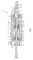
- the unit 1 includes an external tubular frame 3 housing an electric motor 4, which includes, in turn, a stator 5 and a rotor 6 assembled inside the stator 5 to rotate, as regards the same stator 5 and through the interposition of a pair of rolling bearings 7, around its own longitudinal axis 8.
- an electric motor 4 which includes, in turn, a stator 5 and a rotor 6 assembled inside the stator 5 to rotate, as regards the same stator 5 and through the interposition of a pair of rolling bearings 7, around its own longitudinal axis 8.
- the rotor 6 is connected in an angularly fixed manner by means of a splined coupling 9 to a tubular output shaft 10, which is entirely assembled inside the frame 3 coaxially to the axis 8, it is locked along the axis 8 by means of a threaded ring 11, and has an external thread 12 made on an external surface 13 of the same shaft 10.
- the shaft 10 is connected by means of a recirculating ball screw-nut screw coupling 14 of known type to a steering rod 15 including a sleeve 16, which extends around the axis 8 and around the shaft 10, and has a widened portion 17 and a narrowed portion 18 disposed in sequence along the axis 8.
- the portion 17 is equipped with an end section 19, which is limited internally by a surface 20 coaxial to the axis 8, and has an internal thread 21 made on the same surface 20 and connected to the thread 12.
- the rod 15 also includes a cylindrical rod 22, which engages the portion 18, is fixed to the sleeve 16 by means of a fastening screw 23, and protrudes from the portion 18 coaxially to the axis 8 so as to extend through the shaft 10 and to protrude outside the frame 3.
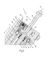
- each wheel 2 is assembled on a relative wheel hub made on a first arm 24 of an equalizer 25, which is hinged to a frame 26 of the vehicle (not shown) to oscillate, as regards the frame 26 and under the force of a connecting rod 27 interposed between the rod 15 and a second arm 28 of the equalizer 25, around a fulcrum axis 29 basically vertical and transversal to the axis 8.
- the connecting rod 27 extends between two axes 30, 31 parallel to the axis 29, and of which the axis 30 is the rotation axis of the connecting rod 27 as regards the rod 15 and the axis 31 is the rotation axis of the connecting rod 27 as regards the arm 28.
- the frame 3 is axially limited by two ring-shaped gaskets 32, which are assembled coaxially to the axis 8, are interposed between the frame 3 and the sleeve 16 and, respectively, between the frame 3 and the rod 22, and they delimit a chamber 33 entirely containing the screw-nut screw coupling 14, i.e. the shaft 10 and the section 19.
- the presence of the gaskets 32 allows, therefore, the lubrication of the coupling 14 exclusively during the assembly of the unit 1.
- the unit 1 is further equipped with a latching device 34 able to angularly lock the shaft 10 around the axis 8 and to prevent, therefore, the axial displacement of the rod 15 in the absence of power supply to the motor 4 allowing the vehicle (not shown) to maintain the same direction of advancement held before the interruption of the electricity supply.
- the device 34 includes a ring-shaped plate 35, which is fixed to the rotor 6 at a right angle to the axis 8, it extends around the rod 22, and has a plurality of seats 36 made parallel to the axis 8 and uniformly distributed around the same axis 8.
- the device 34 further includes a pin 37, which has a longitudinal axis 38 parallel to the axis 8, and is sliding assembled inside a tubular electromagnet 39, that is fixed to the frame 3 coaxially to the axis 38, and is electrically connected to the motor 4 to keep, normally, the pin 37 in a position of release, in which the same pin 37 is positioned outside the seats 36.
- the motor 4 is equipped with a plurality of sensors (not shown), in the case in point Hall effect sensors, which are used both for the switching of the phases to be powered, as well as to control the axial position of the rod 15 avoiding the use of a resolver and/or encoder.
- the motor 4 is further equipped with an electronic control box (not shown) able to calculate the axial position of the rod 15 depending on the number of times that the permanent magnets of the rotor 6 pass in front of the cited sensors (not shown) and depending on the pitch of the threads 12 and 21.
- the operation of the steering unit 1 is easily deducible from that explained above and does not require further explanation.
Landscapes
- Engineering & Computer Science (AREA)
- Chemical & Material Sciences (AREA)
- Combustion & Propulsion (AREA)
- Transportation (AREA)
- Mechanical Engineering (AREA)
- Power Steering Mechanism (AREA)
- Connection Of Motors, Electrical Generators, Mechanical Devices, And The Like (AREA)
Priority Applications (4)
| Application Number | Priority Date | Filing Date | Title |
|---|---|---|---|
| DE602004004240T DE602004004240T2 (de) | 2004-03-10 | 2004-03-10 | Lenkeinheit für ein Elektrofahrzeug |
| ES04425161T ES2277664T3 (es) | 2004-03-10 | 2004-03-10 | Unidad de direccion para un vehiculo electrico. |
| EP04425161A EP1574415B1 (de) | 2004-03-10 | 2004-03-10 | Lenkungseinheit für ein elektrisches Fahrzeug |
| US11/076,574 US7240764B2 (en) | 2004-03-10 | 2005-03-09 | Steering unit for an electric vehicle |
Applications Claiming Priority (1)
| Application Number | Priority Date | Filing Date | Title |
|---|---|---|---|
| EP04425161A EP1574415B1 (de) | 2004-03-10 | 2004-03-10 | Lenkungseinheit für ein elektrisches Fahrzeug |
Publications (2)
| Publication Number | Publication Date |
|---|---|
| EP1574415A1 true EP1574415A1 (de) | 2005-09-14 |
| EP1574415B1 EP1574415B1 (de) | 2007-01-10 |
Family
ID=34814464
Family Applications (1)
| Application Number | Title | Priority Date | Filing Date |
|---|---|---|---|
| EP04425161A Expired - Lifetime EP1574415B1 (de) | 2004-03-10 | 2004-03-10 | Lenkungseinheit für ein elektrisches Fahrzeug |
Country Status (4)
| Country | Link |
|---|---|
| US (1) | US7240764B2 (de) |
| EP (1) | EP1574415B1 (de) |
| DE (1) | DE602004004240T2 (de) |
| ES (1) | ES2277664T3 (de) |
Families Citing this family (5)
| Publication number | Priority date | Publication date | Assignee | Title |
|---|---|---|---|---|
| DE102009045857A1 (de) * | 2009-10-20 | 2011-04-21 | Robert Bosch Gmbh | Verfahren zur Herstellung einer Spindel für einen Spindeltrieb, Wälzgewindetrieb mit einer solchen Spindel und Verwendung des Wälzgewindetriebs |
| US9518672B2 (en) | 2010-06-21 | 2016-12-13 | Cameron International Corporation | Electronically actuated gate valve |
| US20160009386A1 (en) * | 2013-03-20 | 2016-01-14 | Lord Corporation | Low moment force generator devices and methods |
| DE102013211230A1 (de) * | 2013-06-17 | 2014-12-18 | Schaeffler Technologies Gmbh & Co. Kg | Vorrichtung zum Lenken einer Hinterachse eines Kraftfahrzeugs |
| DE102019125792B4 (de) * | 2019-09-25 | 2021-12-16 | Crown Equipment Corp. | Elektrisch betriebenes Lenkungssystem für ein Fahrzeug |
Citations (5)
| Publication number | Priority date | Publication date | Assignee | Title |
|---|---|---|---|---|
| DE3821501A1 (de) * | 1987-07-03 | 1989-01-12 | Zahnradfabrik Friedrichshafen | Zahnstangen-hilfskraftlenkung, insbesondere fuer kraftfahrzeuge |
| EP0528200A1 (de) * | 1991-07-24 | 1993-02-24 | Koyo Seiko Co., Ltd. | Untersetzungsgetriebe für Lenkeinrichtungen |
| WO2003011674A1 (en) * | 2001-07-31 | 2003-02-13 | Delphi Technologies, Inc. | Apparatus and method for steering a vehicle |
| DE10142599A1 (de) * | 2001-08-31 | 2003-04-24 | Opel Adam Ag | Lenksystem für Fahrzeuge |
| EP1354784A1 (de) * | 2002-04-12 | 2003-10-22 | Toyoda Koki Kabushiki Kaisha | Elektrische Servolenkung |
Family Cites Families (5)
| Publication number | Priority date | Publication date | Assignee | Title |
|---|---|---|---|---|
| US4653602A (en) * | 1985-10-17 | 1987-03-31 | General Motors Corporation | Electric motor driven rack and pinion steering gear with take-off from axially slidable nut |
| US6760653B2 (en) * | 2001-05-15 | 2004-07-06 | Trw Inc. | Electric power assisted steering system having a single integrated circuit with two processors |
| JP3839358B2 (ja) * | 2002-06-12 | 2006-11-01 | 株式会社ジェイテクト | 車両の操舵制御装置及び車両の操舵制御方法 |
| EP1413499B1 (de) * | 2002-10-24 | 2008-02-13 | Jtekt Corporation | Lenkwinkelsensor für eine elektrische Servolenkung |
| JP3842235B2 (ja) * | 2003-03-27 | 2006-11-08 | 株式会社ジェイテクト | 制御パラメータの設定方法、制御パラメータの設定装置および電気式動力舵取装置 |
-
2004
- 2004-03-10 ES ES04425161T patent/ES2277664T3/es not_active Expired - Lifetime
- 2004-03-10 EP EP04425161A patent/EP1574415B1/de not_active Expired - Lifetime
- 2004-03-10 DE DE602004004240T patent/DE602004004240T2/de not_active Expired - Lifetime
-
2005
- 2005-03-09 US US11/076,574 patent/US7240764B2/en not_active Expired - Lifetime
Patent Citations (5)
| Publication number | Priority date | Publication date | Assignee | Title |
|---|---|---|---|---|
| DE3821501A1 (de) * | 1987-07-03 | 1989-01-12 | Zahnradfabrik Friedrichshafen | Zahnstangen-hilfskraftlenkung, insbesondere fuer kraftfahrzeuge |
| EP0528200A1 (de) * | 1991-07-24 | 1993-02-24 | Koyo Seiko Co., Ltd. | Untersetzungsgetriebe für Lenkeinrichtungen |
| WO2003011674A1 (en) * | 2001-07-31 | 2003-02-13 | Delphi Technologies, Inc. | Apparatus and method for steering a vehicle |
| DE10142599A1 (de) * | 2001-08-31 | 2003-04-24 | Opel Adam Ag | Lenksystem für Fahrzeuge |
| EP1354784A1 (de) * | 2002-04-12 | 2003-10-22 | Toyoda Koki Kabushiki Kaisha | Elektrische Servolenkung |
Also Published As
| Publication number | Publication date |
|---|---|
| US20050206110A1 (en) | 2005-09-22 |
| DE602004004240T2 (de) | 2007-07-12 |
| US7240764B2 (en) | 2007-07-10 |
| ES2277664T3 (es) | 2007-07-16 |
| EP1574415B1 (de) | 2007-01-10 |
| DE602004004240D1 (de) | 2007-02-22 |
Similar Documents
| Publication | Publication Date | Title |
|---|---|---|
| US10647346B2 (en) | Electrically-powered recirculating-ball steering gear assembly | |
| US10421481B2 (en) | Utility vehicle steering system | |
| EP3726099B1 (de) | Parksperranordnung | |
| KR102582535B1 (ko) | 디스커넥터 장치 | |
| US8864154B2 (en) | Actuator that can be decoupled, in particular having an electromechanical drive | |
| US7401677B2 (en) | Self-centering steering system | |
| US9382972B2 (en) | Reducer of electric power steering apparatus | |
| CN105283620B (zh) | 门开闭装置 | |
| EP0947734A1 (de) | Elektrischer stellantrieb | |
| US11975576B2 (en) | Trailer coupling | |
| GB2146300A (en) | Power assist steering gear assembly | |
| US20210261186A1 (en) | Steering system | |
| US20070209862A1 (en) | Steering system with hollow shaft electric motor and intermediate transmission | |
| US7766777B2 (en) | Device for superimposing rotational speeds, comprising a servodrive | |
| CN1935575A (zh) | 汽车用电动转向装置 | |
| US9103422B2 (en) | Ball screw actuator including a compliant ball screw stop | |
| US9469335B2 (en) | Rear wheel steering apparatus for vehicle | |
| JP2019519419A (ja) | 操作装置を有するステアリングシステム並びに操作装置を有するステアリングシステムの使用 | |
| WO2015036329A1 (en) | Linear drive device and exhaust gas recirculation control valve | |
| US7240764B2 (en) | Steering unit for an electric vehicle | |
| CN112292306B (zh) | 具有主轴驱动器的线控转向装置 | |
| CN104742956B (zh) | 后轮转向装置的转向连杆结构 | |
| US7121379B2 (en) | Steering unit for an electric vehicle | |
| CN106763751A (zh) | 一种电动汽车驻车p档伺服电机驱动的滚珠丝杆执行机构 | |
| EP3153735B1 (de) | Zusätzliches bremssystem |
Legal Events
| Date | Code | Title | Description |
|---|---|---|---|
| PUAI | Public reference made under article 153(3) epc to a published international application that has entered the european phase |
Free format text: ORIGINAL CODE: 0009012 |
|
| AK | Designated contracting states |
Kind code of ref document: A1 Designated state(s): AT BE BG CH CY CZ DE DK EE ES FI FR GB GR HU IE IT LI LU MC NL PL PT RO SE SI SK TR |
|
| AX | Request for extension of the european patent |
Extension state: AL LT LV MK |
|
| 17P | Request for examination filed |
Effective date: 20060313 |
|
| AKX | Designation fees paid |
Designated state(s): AT BE BG CH CY CZ DE DK EE ES FI FR GB GR HU IE IT LI LU MC NL PL PT RO SE SI SK TR |
|
| GRAP | Despatch of communication of intention to grant a patent |
Free format text: ORIGINAL CODE: EPIDOSNIGR1 |
|
| GRAS | Grant fee paid |
Free format text: ORIGINAL CODE: EPIDOSNIGR3 |
|
| GRAA | (expected) grant |
Free format text: ORIGINAL CODE: 0009210 |
|
| RAP1 | Party data changed (applicant data changed or rights of an application transferred) |
Owner name: UMBRA CUSCINETTI S.P.A. |
|
| AK | Designated contracting states |
Kind code of ref document: B1 Designated state(s): AT BE BG CH CY CZ DE DK EE ES FI FR GB GR HU IE IT LI LU MC NL PL PT RO SE SI SK TR |
|
| PG25 | Lapsed in a contracting state [announced via postgrant information from national office to epo] |
Ref country code: LI Free format text: LAPSE BECAUSE OF FAILURE TO SUBMIT A TRANSLATION OF THE DESCRIPTION OR TO PAY THE FEE WITHIN THE PRESCRIBED TIME-LIMIT Effective date: 20070110 Ref country code: NL Free format text: LAPSE BECAUSE OF FAILURE TO SUBMIT A TRANSLATION OF THE DESCRIPTION OR TO PAY THE FEE WITHIN THE PRESCRIBED TIME-LIMIT Effective date: 20070110 Ref country code: AT Free format text: LAPSE BECAUSE OF FAILURE TO SUBMIT A TRANSLATION OF THE DESCRIPTION OR TO PAY THE FEE WITHIN THE PRESCRIBED TIME-LIMIT Effective date: 20070110 Ref country code: CH Free format text: LAPSE BECAUSE OF FAILURE TO SUBMIT A TRANSLATION OF THE DESCRIPTION OR TO PAY THE FEE WITHIN THE PRESCRIBED TIME-LIMIT Effective date: 20070110 Ref country code: PL Free format text: LAPSE BECAUSE OF FAILURE TO SUBMIT A TRANSLATION OF THE DESCRIPTION OR TO PAY THE FEE WITHIN THE PRESCRIBED TIME-LIMIT Effective date: 20070110 Ref country code: FI Free format text: LAPSE BECAUSE OF FAILURE TO SUBMIT A TRANSLATION OF THE DESCRIPTION OR TO PAY THE FEE WITHIN THE PRESCRIBED TIME-LIMIT Effective date: 20070110 Ref country code: SI Free format text: LAPSE BECAUSE OF FAILURE TO SUBMIT A TRANSLATION OF THE DESCRIPTION OR TO PAY THE FEE WITHIN THE PRESCRIBED TIME-LIMIT Effective date: 20070110 Ref country code: DK Free format text: LAPSE BECAUSE OF FAILURE TO SUBMIT A TRANSLATION OF THE DESCRIPTION OR TO PAY THE FEE WITHIN THE PRESCRIBED TIME-LIMIT Effective date: 20070110 |
|
| REG | Reference to a national code |
Ref country code: GB Ref legal event code: FG4D |
|
| REG | Reference to a national code |
Ref country code: IE Ref legal event code: FG4D |
|
| REF | Corresponds to: |
Ref document number: 602004004240 Country of ref document: DE Date of ref document: 20070222 Kind code of ref document: P |
|
| PG25 | Lapsed in a contracting state [announced via postgrant information from national office to epo] |
Ref country code: BG Free format text: LAPSE BECAUSE OF FAILURE TO SUBMIT A TRANSLATION OF THE DESCRIPTION OR TO PAY THE FEE WITHIN THE PRESCRIBED TIME-LIMIT Effective date: 20070410 Ref country code: SE Free format text: LAPSE BECAUSE OF FAILURE TO SUBMIT A TRANSLATION OF THE DESCRIPTION OR TO PAY THE FEE WITHIN THE PRESCRIBED TIME-LIMIT Effective date: 20070410 |
|
| PG25 | Lapsed in a contracting state [announced via postgrant information from national office to epo] |
Ref country code: PT Free format text: LAPSE BECAUSE OF FAILURE TO SUBMIT A TRANSLATION OF THE DESCRIPTION OR TO PAY THE FEE WITHIN THE PRESCRIBED TIME-LIMIT Effective date: 20070611 |
|
| ET | Fr: translation filed | ||
| NLV1 | Nl: lapsed or annulled due to failure to fulfill the requirements of art. 29p and 29m of the patents act | ||
| REG | Reference to a national code |
Ref country code: ES Ref legal event code: FG2A Ref document number: 2277664 Country of ref document: ES Kind code of ref document: T3 |
|
| REG | Reference to a national code |
Ref country code: CH Ref legal event code: PL |
|
| PLBE | No opposition filed within time limit |
Free format text: ORIGINAL CODE: 0009261 |
|
| STAA | Information on the status of an ep patent application or granted ep patent |
Free format text: STATUS: NO OPPOSITION FILED WITHIN TIME LIMIT |
|
| PG25 | Lapsed in a contracting state [announced via postgrant information from national office to epo] |
Ref country code: SK Free format text: LAPSE BECAUSE OF FAILURE TO SUBMIT A TRANSLATION OF THE DESCRIPTION OR TO PAY THE FEE WITHIN THE PRESCRIBED TIME-LIMIT Effective date: 20070110 |
|
| 26N | No opposition filed |
Effective date: 20071011 |
|
| PG25 | Lapsed in a contracting state [announced via postgrant information from national office to epo] |
Ref country code: BE Free format text: LAPSE BECAUSE OF FAILURE TO SUBMIT A TRANSLATION OF THE DESCRIPTION OR TO PAY THE FEE WITHIN THE PRESCRIBED TIME-LIMIT Effective date: 20070110 Ref country code: CZ Free format text: LAPSE BECAUSE OF FAILURE TO SUBMIT A TRANSLATION OF THE DESCRIPTION OR TO PAY THE FEE WITHIN THE PRESCRIBED TIME-LIMIT Effective date: 20070110 Ref country code: RO Free format text: LAPSE BECAUSE OF FAILURE TO SUBMIT A TRANSLATION OF THE DESCRIPTION OR TO PAY THE FEE WITHIN THE PRESCRIBED TIME-LIMIT Effective date: 20070110 |
|
| PG25 | Lapsed in a contracting state [announced via postgrant information from national office to epo] |
Ref country code: MC Free format text: LAPSE BECAUSE OF NON-PAYMENT OF DUE FEES Effective date: 20070331 Ref country code: IE Free format text: LAPSE BECAUSE OF NON-PAYMENT OF DUE FEES Effective date: 20070312 |
|
| PG25 | Lapsed in a contracting state [announced via postgrant information from national office to epo] |
Ref country code: GR Free format text: LAPSE BECAUSE OF FAILURE TO SUBMIT A TRANSLATION OF THE DESCRIPTION OR TO PAY THE FEE WITHIN THE PRESCRIBED TIME-LIMIT Effective date: 20070411 |
|
| PG25 | Lapsed in a contracting state [announced via postgrant information from national office to epo] |
Ref country code: EE Free format text: LAPSE BECAUSE OF FAILURE TO SUBMIT A TRANSLATION OF THE DESCRIPTION OR TO PAY THE FEE WITHIN THE PRESCRIBED TIME-LIMIT Effective date: 20070110 |
|
| PG25 | Lapsed in a contracting state [announced via postgrant information from national office to epo] |
Ref country code: CY Free format text: LAPSE BECAUSE OF FAILURE TO SUBMIT A TRANSLATION OF THE DESCRIPTION OR TO PAY THE FEE WITHIN THE PRESCRIBED TIME-LIMIT Effective date: 20070110 |
|
| PG25 | Lapsed in a contracting state [announced via postgrant information from national office to epo] |
Ref country code: LU Free format text: LAPSE BECAUSE OF NON-PAYMENT OF DUE FEES Effective date: 20070310 |
|
| PG25 | Lapsed in a contracting state [announced via postgrant information from national office to epo] |
Ref country code: TR Free format text: LAPSE BECAUSE OF FAILURE TO SUBMIT A TRANSLATION OF THE DESCRIPTION OR TO PAY THE FEE WITHIN THE PRESCRIBED TIME-LIMIT Effective date: 20070110 Ref country code: HU Free format text: LAPSE BECAUSE OF FAILURE TO SUBMIT A TRANSLATION OF THE DESCRIPTION OR TO PAY THE FEE WITHIN THE PRESCRIBED TIME-LIMIT Effective date: 20070711 |
|
| REG | Reference to a national code |
Ref country code: FR Ref legal event code: PLFP Year of fee payment: 13 |
|
| REG | Reference to a national code |
Ref country code: FR Ref legal event code: PLFP Year of fee payment: 14 |
|
| REG | Reference to a national code |
Ref country code: FR Ref legal event code: PLFP Year of fee payment: 15 |
|
| REG | Reference to a national code |
Ref country code: ES Ref legal event code: PC2A Effective date: 20180619 Ref country code: ES Ref legal event code: PC2A Owner name: UMBRAGROUP S.P.A. Effective date: 20180619 |
|
| REG | Reference to a national code |
Ref country code: DE Ref legal event code: R082 Ref document number: 602004004240 Country of ref document: DE Representative=s name: SPARING - ROEHL - HENSELER, DE Ref country code: DE Ref legal event code: R081 Ref document number: 602004004240 Country of ref document: DE Owner name: UMBRAGROUP S.P.A., IT Free format text: FORMER OWNER: UMBRA CUSCINETTI S.P.A., FOLIGNO, IT |
|
| REG | Reference to a national code |
Ref country code: FR Ref legal event code: CA Effective date: 20180910 Ref country code: FR Ref legal event code: CD Owner name: UMBRAGROUP S.P.A., IT Effective date: 20180910 |
|
| PGFP | Annual fee paid to national office [announced via postgrant information from national office to epo] |
Ref country code: FR Payment date: 20230322 Year of fee payment: 20 |
|
| PGFP | Annual fee paid to national office [announced via postgrant information from national office to epo] |
Ref country code: IT Payment date: 20230316 Year of fee payment: 20 Ref country code: GB Payment date: 20230321 Year of fee payment: 20 Ref country code: DE Payment date: 20230321 Year of fee payment: 20 |
|
| P01 | Opt-out of the competence of the unified patent court (upc) registered |
Effective date: 20230602 |
|
| PGFP | Annual fee paid to national office [announced via postgrant information from national office to epo] |
Ref country code: ES Payment date: 20230527 Year of fee payment: 20 |
|
| P02 | Opt-out of the competence of the unified patent court (upc) changed |
Effective date: 20230821 |
|
| REG | Reference to a national code |
Ref country code: DE Ref legal event code: R071 Ref document number: 602004004240 Country of ref document: DE |
|
| REG | Reference to a national code |
Ref country code: ES Ref legal event code: FD2A Effective date: 20240327 |
|
| REG | Reference to a national code |
Ref country code: GB Ref legal event code: PE20 Expiry date: 20240309 |
|
| PG25 | Lapsed in a contracting state [announced via postgrant information from national office to epo] |
Ref country code: ES Free format text: LAPSE BECAUSE OF EXPIRATION OF PROTECTION Effective date: 20240311 |
|
| PG25 | Lapsed in a contracting state [announced via postgrant information from national office to epo] |
Ref country code: ES Free format text: LAPSE BECAUSE OF EXPIRATION OF PROTECTION Effective date: 20240311 Ref country code: GB Free format text: LAPSE BECAUSE OF EXPIRATION OF PROTECTION Effective date: 20240309 |