EP1574384B1 - System and method assisting a vehicle driver via changes in accelerator reaction force and engine output characteristic - Google Patents
System and method assisting a vehicle driver via changes in accelerator reaction force and engine output characteristic Download PDFInfo
- Publication number
- EP1574384B1 EP1574384B1 EP05003694A EP05003694A EP1574384B1 EP 1574384 B1 EP1574384 B1 EP 1574384B1 EP 05003694 A EP05003694 A EP 05003694A EP 05003694 A EP05003694 A EP 05003694A EP 1574384 B1 EP1574384 B1 EP 1574384B1
- Authority
- EP
- European Patent Office
- Prior art keywords
- accelerator
- reaction force
- vehicle
- different
- engine output
- Prior art date
- Legal status (The legal status is an assumption and is not a legal conclusion. Google has not performed a legal analysis and makes no representation as to the accuracy of the status listed.)
- Expired - Lifetime
Links
Images


Classifications
-
- F—MECHANICAL ENGINEERING; LIGHTING; HEATING; WEAPONS; BLASTING
- F02—COMBUSTION ENGINES; HOT-GAS OR COMBUSTION-PRODUCT ENGINE PLANTS
- F02D—CONTROLLING COMBUSTION ENGINES
- F02D11/00—Arrangements for, or adaptations to, non-automatic engine control initiation means, e.g. operator initiated
- F02D11/06—Arrangements for, or adaptations to, non-automatic engine control initiation means, e.g. operator initiated characterised by non-mechanical control linkages, e.g. fluid control linkages or by control linkages with power drive or assistance
- F02D11/10—Arrangements for, or adaptations to, non-automatic engine control initiation means, e.g. operator initiated characterised by non-mechanical control linkages, e.g. fluid control linkages or by control linkages with power drive or assistance of the electric type
- F02D11/105—Arrangements for, or adaptations to, non-automatic engine control initiation means, e.g. operator initiated characterised by non-mechanical control linkages, e.g. fluid control linkages or by control linkages with power drive or assistance of the electric type characterised by the function converting demand to actuation, e.g. a map indicating relations between an accelerator pedal position and throttle valve opening or target engine torque
-
- B—PERFORMING OPERATIONS; TRANSPORTING
- B60—VEHICLES IN GENERAL
- B60W—CONJOINT CONTROL OF VEHICLE SUB-UNITS OF DIFFERENT TYPE OR DIFFERENT FUNCTION; CONTROL SYSTEMS SPECIALLY ADAPTED FOR HYBRID VEHICLES; ROAD VEHICLE DRIVE CONTROL SYSTEMS FOR PURPOSES NOT RELATED TO THE CONTROL OF A PARTICULAR SUB-UNIT
- B60W10/00—Conjoint control of vehicle sub-units of different type or different function
- B60W10/04—Conjoint control of vehicle sub-units of different type or different function including control of propulsion units
-
- B—PERFORMING OPERATIONS; TRANSPORTING
- B60—VEHICLES IN GENERAL
- B60W—CONJOINT CONTROL OF VEHICLE SUB-UNITS OF DIFFERENT TYPE OR DIFFERENT FUNCTION; CONTROL SYSTEMS SPECIALLY ADAPTED FOR HYBRID VEHICLES; ROAD VEHICLE DRIVE CONTROL SYSTEMS FOR PURPOSES NOT RELATED TO THE CONTROL OF A PARTICULAR SUB-UNIT
- B60W50/00—Details of control systems for road vehicle drive control not related to the control of a particular sub-unit, e.g. process diagnostic or vehicle driver interfaces
- B60W50/08—Interaction between the driver and the control system
- B60W50/14—Means for informing the driver, warning the driver or prompting a driver intervention
- B60W50/16—Tactile feedback to the driver, e.g. vibration or force feedback to the driver on the steering wheel or the accelerator pedal
-
- F—MECHANICAL ENGINEERING; LIGHTING; HEATING; WEAPONS; BLASTING
- F02—COMBUSTION ENGINES; HOT-GAS OR COMBUSTION-PRODUCT ENGINE PLANTS
- F02D—CONTROLLING COMBUSTION ENGINES
- F02D41/00—Electrical control of supply of combustible mixture or its constituents
- F02D41/02—Circuit arrangements for generating control signals
- F02D41/021—Introducing corrections for particular conditions exterior to the engine
-
- F—MECHANICAL ENGINEERING; LIGHTING; HEATING; WEAPONS; BLASTING
- F02—COMBUSTION ENGINES; HOT-GAS OR COMBUSTION-PRODUCT ENGINE PLANTS
- F02D—CONTROLLING COMBUSTION ENGINES
- F02D41/00—Electrical control of supply of combustible mixture or its constituents
- F02D41/24—Electrical control of supply of combustible mixture or its constituents characterised by the use of digital means
- F02D41/2406—Electrical control of supply of combustible mixture or its constituents characterised by the use of digital means using essentially read only memories
- F02D41/2409—Addressing techniques specially adapted therefor
- F02D41/2422—Selective use of one or more tables
-
- B—PERFORMING OPERATIONS; TRANSPORTING
- B60—VEHICLES IN GENERAL
- B60K—ARRANGEMENT OR MOUNTING OF PROPULSION UNITS OR OF TRANSMISSIONS IN VEHICLES; ARRANGEMENT OR MOUNTING OF PLURAL DIVERSE PRIME-MOVERS IN VEHICLES; AUXILIARY DRIVES FOR VEHICLES; INSTRUMENTATION OR DASHBOARDS FOR VEHICLES; ARRANGEMENTS IN CONNECTION WITH COOLING, AIR INTAKE, GAS EXHAUST OR FUEL SUPPLY OF PROPULSION UNITS IN VEHICLES
- B60K26/00—Arrangement or mounting of propulsion-unit control devices in vehicles
- B60K26/02—Arrangement or mounting of propulsion-unit control devices in vehicles of initiating means or elements
- B60K26/021—Arrangement or mounting of propulsion-unit control devices in vehicles of initiating means or elements with means for providing feel, e.g. by changing pedal force characteristics
-
- B—PERFORMING OPERATIONS; TRANSPORTING
- B60—VEHICLES IN GENERAL
- B60W—CONJOINT CONTROL OF VEHICLE SUB-UNITS OF DIFFERENT TYPE OR DIFFERENT FUNCTION; CONTROL SYSTEMS SPECIALLY ADAPTED FOR HYBRID VEHICLES; ROAD VEHICLE DRIVE CONTROL SYSTEMS FOR PURPOSES NOT RELATED TO THE CONTROL OF A PARTICULAR SUB-UNIT
- B60W2554/00—Input parameters relating to objects
Definitions
- the present invention relates to a system and method for assisting a driver of a vehicle traveling on a road.
- the conventional art describes various methods and systems for assisting a driver of a vehicle.
- This system comprises a data acquisition system acquiring data including information on status of a vehicle and information on environment in a field around the vehicle, a controller, and at least one actuator.
- the controller determines a future environment in the field around the vehicle using the acquired data, for making an operator response plan in response to the determined future environment, which plan prompts the operator to operate the vehicle in a desired manner for the determined future environment.
- the actuator is coupled to a driver controlled input device to mechanically affect operation of the input device in a manner that prompts, via a haptic input from the driver controlled input device, the driver to operate the vehicle in the desired manner.
- JP2003-063430 Another example of such a system is described in JP2003-063430 .
- This system transmits the relationship between a vehicle and an obstacle in front of the vehicle to a driver of the vehicle via a continuous change in reaction force from an accelerator pedal.
- the reaction force varies continuously with different stages of the relationship.
- JP10-166889 Still another example of such a system is described in JP10-166889 .
- This system alerts a driver by regulating reaction force from an accelerator pedal when a distance to an obstacle becomes shorter than a predetermined value.
- EP-A-1 375 234 discloses a system for assisting a driver operating a vehicle travelling on a road, the system comprising an engine controller regulating operation of an engine of the vehicle to provide a desired engine output characteristic; control logic that controls the engine controller to modify the engine output characteristic in response to at least one of a detected state of an environment around the vehicle and a determined risk.
- EP-A-1 375 232 describes an accelerator pedal device that selects a characteristic between a first characteristic according to a running situation of the subject vehicle and a second characteristic specified regardless of the running situation of the vehicle.
- the first characteristic and the second characteristic each is a characteristic indicating a relationship between an amount of stepping upon of the accelerator pedal and the reaction force to be applied.
- the reaction force application device applies the reaction force to the accelerator pedal based upon the characteristic selected by the selection device.
- EP-A-1 375 280 refers to a driving assist system for a vehicle calculating an accelerator pedal reaction force command value based upon a risk potential.
- An object of the present invention is to provide a less complicated and less expensive system and method for assisting a driver operating a vehicle traveling on a road.
- a system for assisting a driver operating a vehicle traveling on a road.
- the system comprises an engine controller regulating operation of an engine of the vehicle to provide a desired engine output characteristic.
- Control logic is provided that controls the engine controller to modify the engine output characteristic in response to at least one of a detected state of an environment around the vehicle and a determined risk.
- An accelerator is also provided, having different positions and selectively producing different acceleration reaction force characteristics. Each different acceleration reaction force characteristic provides varying of reaction force with different positions of the accelerator.
- the reference numeral 1 generally denotes one embodiment of a system for assisting a driver operating a motor vehicle (see Fig. 2 ) by manipulating an accelerator or gas pedal 80.
- the system 1 includes a scene recognition device detecting the state of the environment around the vehicle.
- the scene recognition device includes a radar device 10.
- the radar device 10 is positioned at a center of a front grill or a front bumper of the vehicle for transmitting pulsed beam or radar waves ahead of the vehicle in order to detect obstacles within the field of view of the radar.
- the radar device 10 may be a conventional millimeter wave, frequently modulated continuous (FMCW) radar
- the radar device 10 in this embodiment, is an infrared laser radar.
- An infrared pulsed beam travels, as a transmitted beam, toward a measurement zone.
- a light receiving device receives the transmitted beam returning from an obstacle inside the measurement zone.
- the pulsed beam can be swiveled horizontally due to the rotation of the polygonal mirror, and the pulsed beam can be swiveled vertically due to a plurality of mirror surfaces of the polygonal mirror inclined at different angles.
- the pulsed beam can be swiveled horizontally and laterally about 6 degrees to each side of a longitudinal line passing through the center of the vehicle 1.
- a distance and azimuth angle between each of the detected obstacle(s) and the vehicle can be determined.
- the scene recognition device also includes a vehicle speed sensor 30.
- the vehicle speed sensor 30 detects a speed of the vehicle by measuring a speed of each of the road wheels or a speed of an output shaft of a transmission.
- a first control logic or controller 50 determines risk RP.
- the control logic 50 proceeds to determine whether or not the determined risk RP is greater than a predetermined value RP0. If this is the case, the control logic 50 determines that the risk RP should be transmitted to the driver.
- control logic 60 In response to the detected state of the environment around the vehicle or the determined risk RP, control logic 60 generates a control signal fed to an accelerator pedal unit 80.
- the control logic 60 determines which one out of different accelerator pedal reaction force characteristics as shown, for example, in Fig. 5 or 7 or 8 , the accelerator pedal unit 80 should select and produce.
- the result of determination by the control logic 50 and position of the accelerator pedal 80 are used as the basis for the control logic 60 to make the determination. Once, the determination is made, the control logic 60 creates the control signal to be fed to the accelerator pedal unit 80.
- the embodiment may well be understood from description of the accelerator pedal unit 80
- the accelerator pedal unit 80 has a pedal 81, which may take different positions upon receiving stress when the driver steps on the pedal 81.
- the pedal 81 is supported by a lever 82.
- the lever 82 is attached to the pedal 81.
- the lever 82 is pivotally supported by a base plate 83 fixed to the vehicle body.
- the base plate 83 has a first rotary shaft 88 supported by bearings 84, and the rotary shaft 88 is fixed to that portion of the lever 82 between the one and the opposite end.
- the lever 82 has a bracket 86 anchoring one end of a first tensile spring 85.
- the first tensile spring 85 is anchored to a bracket 87 that is fixed to the base plate 83.
- a stroke sensor 70 measures an amount of rotation of the rotary shaft 88. The stroke sensor 70 determines the position S of the accelerator pedal 81 based on the rotation amount measurement and generates a sensor signal indicative of the position S.
- the base plate has a second rotary shaft 62.
- the second rotary shaft 62 is supported by bearings 63.
- the second rotary shaft 62 is fixed to a bracket 64 at one end thereof.
- the bracket 64 anchors one end of a second tensile spring 65.
- the second tensile spring 65 is anchored to a bracket 66 that is fixed to the base plate 83.
- An electromagnetically operated torque transmitting unit 61 in the form of, for example, an electromagnetically operated clutch, is provided to establish torque transmission between the first and second rotary shafts 88 and 62.
- electric current passing through the electromagnetically operated clutch 61 is regulated.
- the electromagnetically operated clutch 61 is disengaged, the second rotary shaft 62 is disconnected.
- the first tensile spring 85 give reaction force to the driver via the pedal 81.
- the second tensile spring 65 fully cooperates with the first tensile spring 85 to give increased reaction force to the driver via the pedal 81.
- the determined risk RP at the control logic 50 is transmitted to a control logic 90.
- the control logic 90 selects one of data of different engine output characteristics, each in the form of a pattern of variation of correction amount with different positions S of the pedal 81, and determines a correction amount.
- the control logic 90 generates a correction signal indicative of the correction amount to modify an engine control signal fed to an engine controller 91.
- the engine controller 91 regulates operation of an engine of the vehicle to provide an engine output characteristic of varying of engine output with the different positions S of the accelerator pedal 81.
- control logic 90 modifies operation of the engine controller 91 to modify the engine output characteristic.
- the control logic or controller 50 may contain a microprocessor including as usual a central processing unit (CPU), and computer readable storage medium, such as a read only memory (ROM), a random access memory (RAM).
- a microprocessor including as usual a central processing unit (CPU), and computer readable storage medium, such as a read only memory (ROM), a random access memory (RAM).
- ROM read only memory
- RAM random access memory
- the control logic 60 and control logic 90 are illustrated as elements physically separated from the control logic 50.
- Each of the control logics 50, 60 and 90 may contain a microprocessor. However, if desired, as is so in the embodiment, the control logics 50, 60 and 90 may share a common microprocessor. In this case, the control logic 50, 60 and 90 are software implemented.
- the microprocessor repeats execution of a control routine at regular intervals of, for example, 50 milliseconds.
- the microprocessor performs a reading operation of the output of the scene recognition device (radar device 10, vehicle speed sensor 30), and the stroke sensor 70 to receive, as inputs, a vehicle speed v1, a vehicle speed v2 of the preceding vehicle, if available, a distance d to the preceding vehicle, a relative speed vr between the vehicles, and a position S of the accelerator pedal 81.
- the scene recognition device radar device 10, vehicle speed sensor 30
- the stroke sensor 70 to receive, as inputs, a vehicle speed v1, a vehicle speed v2 of the preceding vehicle, if available, a distance d to the preceding vehicle, a relative speed vr between the vehicles, and a position S of the accelerator pedal 81.
- the microprocessor determines a time headway THW and a time to collision TTC between the vehicle and the preceding vehicle by using the equations 1 and 2 described above.
- the microprocessor determines a risk RP by using the equation 3.
- the microprocessor determines whether or not the determined risk RP is greater than a predetermined value RP0. If this is the case (RP > RP0), the microprocessor recognizes that the determined risk should be transmitted to the driver and proceeds to determine, at step S105, whether or not the accelerator pedal 81 is released by checking if the position S is zero. If this is not the case (RP ⁇ RP0), the microprocessor proceeds to determine, at step S107, whether or not the accelerator pedal 81 is released by checking if the position S is zero.
- step S105 the microprocessor proceeds to select, at step S106, the accelerator pedal reaction force characteristic (see the one-dot chain line in Fig. 5 ) that is appropriate to the environment involving detection of the preceding vehicle.
- step S106 the accelerator pedal reaction force characteristic (see the one-dot chain line in Fig. 5 ) that is appropriate to the environment involving detection of the preceding vehicle.
- Engaging the electromagnetically operated clutch 61 allows both of the first and second springs 85 and 65 to cooperate with each other to produce increased reaction force F.
- the two different accelerator pedal reaction force characteristics are different from each other in the absolute value of reaction force F over a portion of the whole range of different positions S of the accelerator pedal 81. Over the portion of the whole range of different position S of the accelerator pedal 81, the two different accelerator pedal reaction force characteristics are different from each other in a change in reaction force F per unit change in position of the accelerator.
- the one-dot chain line drawn characteristic provides increased absolute value in reaction force F at each position S of the accelerator pedal 81.
- the driver feels this increased reaction force via the accelerator pedal 81.
- the one-dot chain line drawn characteristic also provides a higher increase in reaction force F per unit increase in position S of the accelerator pedal 81.
- the driver feels greater increase in reaction force F upon depressing the accelerator pedal 81. Via such tactile or haptic inputs, the presence of substantial risk RP is transmitted to the driver.
- step S107 the microprocessor proceeds to select, at step S108, normal accelerator pedal reaction force characteristic (see the solid line in Fig. 5 ). Once this characteristic has been selected at step S108 and a switch to this characteristic has been completed by disengaging the electromagnetically operated clutch 61, the microprocessor proceeds from step S107 directly to step S109.
- the microprocessor changes the engine output characteristic in response to the determined risk RP at step S103.
- the solid line indicates the normal engine output characteristic that is selected upon detection of no preceding vehicle. According to this characteristic, the engine output is proportional to the position S of the accelerator pedal 81.
- a threshold value Sa at which the engine output begins to appear, shifts in a direction of increasing the position S of the accelerator pedal 81 as the determined risk RP increases.
- the illustrated one-dot chain lines show modified engine output characteristics. Since no engine output is produced until the driver depressed the accelerator pedal 81 down to the threshold value Sa, there is an increasing play of the accelerator pedal 81 as the risk RP increases.
- a change in engine output per unit increase in position of the accelerator pedal 81 increases as the risk RP increases.
- the engine output characteristic is common at positions of the accelerator pedal 81 exceeding a predetermined value Sb.
- the engine output characteristic needs to shift toward the solid normal engine output characteristic. Gradual shift is preferred using, for example, a first-order delay filter. However, it the accelerator pedal 81 is released, a quick return to the solid normal engine output characteristic may be allowed.
- the engine controller 91 controls an engine power control element, for example, a throttle valve, to regulate operation of the engine for production of an engine output characteristic of varying of engine output with the different positions S of the accelerator pedal 81.
- an engine power control element for example, a throttle valve
- the reaction force characteristic indicated by the one-dot chain line in Figs. 5 and 7 is just one of various examples used in the embodiment according to the present invention.
- Another example is the use of different accelerator pedal reaction force characteristics that are different from each other in the absolute value of reaction force over at least a portion of the whole range of different positions of the accelerator.
- Another example is the use of different accelerator pedal reaction force characteristics that are different from each other in a change in reaction force per unit change in position of the accelerator pedal over at least a portion of the whole range of the different positions of the accelerator pedal.
- Fig. 8 shows another example of the accelerator pedal reaction force characteristics.
- the one-dot chain line drawn characteristic is selected upon or after the determined risk RP has exceeded the predetermined value RP0.
- This reaction force characteristic produces a first small increase in reaction force F per unit increase in position of the accelerator pedal 81 over a first portion, below a position Sc, of the whole range of the different positions of the accelerator pedal and a second large increase in reaction force F per unit increase in position S of the accelerator pedal over a second portion, in excess of the position Sc, of the whole range of the different positions S of the accelerator pedal 81.
- the accelerator pedal reaction force F slowly increases in the same manner as the fully drawn normal reaction force characteristic until the position S of the accelerator pedal 81 reaches the predetermined value Sc. Once the accelerator pedal 81 is depressed further deeply beyond the predetermined value Sc, the reaction force F increases quickly.
- the modified engine output characteristics variable with the risk RP are designed such that, at the predetermined position Sc, the most appropriate engine output is produced to follow the preceding vehicle.
- the driver may easily keep the position S of the accelerator pedal at the predetermined position Sc, at which the most appropriate engine output is produced for the vehicle to follow the preceding vehicle.
- the one-dot chain line drawn characteristic may be realized by using a non-linear spring as the second tensile spring 65 or by additionally providing a third spring.
- Such third spring is connected to the pedal 81 via an appropriate slide mechanism. The slide starts sliding when the accelerator pedal 81 is depressed deeply beyond the predetermined value Sc to apply spring force of the third spring to the pedal 81.
- the driver is allowed to depress the accelerator pedal 81 within a region (S ⁇ Sc), but discouraged to depress the accelerator pedal 81 within another region (S ⁇ Sc).
- S ⁇ Sc region
- the engine output characteristic to produce the most appropriate engine output for the vehicle to follow the preceding vehicle at the predetermined position Sc, it is possible to realize a vehicle characteristic that allows the driver to follow the preceding vehicle only by keeping the accelerator pedal at the predetermined position Sc as directed by the difference in reaction force.
- two different springs may be connected to the accelerator pedal 81 alternately.
- the two rotary shafts 88 and 62 may be interconnected by a pin that may be removed by a solenoid device. In this case, the electromagnetically operated clutch is no longer needed.
- the laser radar 10 and the vehicle speed sensor 30 function as the scene recognition device.
- the scene recognition device is not limited to this example.
- Another example is the use of a millimeter wave frequency modulated continuous (FMCW) radar and/or a CCD camera and/or a MOS camera instead of the laser radar 10.
- FMCW millimeter wave frequency modulated continuous
- the controller 50 functions as the control logic determining risk based on the detected state of environment around the vehicle.
- control logic 60 determines which one out of different accelerator pedal reaction force characteristics as shown, for example, in Fig 5 or 7 or 8 , the accelerator pedal unit 80 should select and produce. It is appreciated that the control logic 60 is responsible for a shift in accelerator pedal reaction force characteristic. It is to be noted that the control logic 60 is not limited to the software implementation. The control logic 60 may be implemented in hardware in the form of a device, namely, an accelerator pedal reaction force shifting device.
- control logic 90 selects one of data of different engine output characteristics and the engine controller 91 regulates operation of the engine to accomplish the selected engine output characteristic. It is appreciated that the control logic 90 modifies operation of the engine controller 91 to modify the engine output characteristic. It is to be noted that the control logic 90 is not limited to the software implementation.
- the control logic 90 may be implemented in hardware in the form of a device, namely, an engine output characteristic modifying device.
- the stroke sensor 70 is used to detect amount of driver's manual operation of the accelerator pedal 81.
- the sensor is not limited to the stroke sensor 70.
- Another sensor may be used instead of the stroke sensor 70 to detect the amount of driver's manual operation of the accelerator pedal 81.
- the present invention is not limited to selection of one of two accelerator pedal reaction characteristics. Three different reaction force characteristics may be made by using more than two springs having different spring characteristics.
- modifying the engine output characteristic it is possible to modify the characteristic in response to a relative speed between the vehicle and the preceding vehicle and/or a distance to the preceding vehicle. For example, an increase in engine output per an unit accelerator pedal position S is suppressed as the absolute value of the relative speed vr increases and/or the distance becomes short. In this manner, the relationship between the vehicle and the preceding vehicle may be expressed by the relative speed vr and/or the distance d instead of the risk RP.
Landscapes
- Engineering & Computer Science (AREA)
- Combustion & Propulsion (AREA)
- Chemical & Material Sciences (AREA)
- Mechanical Engineering (AREA)
- General Engineering & Computer Science (AREA)
- Automation & Control Theory (AREA)
- Transportation (AREA)
- Human Computer Interaction (AREA)
- Auxiliary Drives, Propulsion Controls, And Safety Devices (AREA)
- Control Of Throttle Valves Provided In The Intake System Or In The Exhaust System (AREA)
- Traffic Control Systems (AREA)
- Control Of Driving Devices And Active Controlling Of Vehicle (AREA)
- Combined Controls Of Internal Combustion Engines (AREA)
Description
- The present application claims the benefit of priority from
Japanese Patent Application No. 2004-69514, filed March 11, 2004 - The present invention relates to a system and method for assisting a driver of a vehicle traveling on a road.
- The conventional art describes various methods and systems for assisting a driver of a vehicle.
- One example of such a system is described in
US 2003/0060936 A1 , published Mar. 27, 2003. This system comprises a data acquisition system acquiring data including information on status of a vehicle and information on environment in a field around the vehicle, a controller, and at least one actuator. The controller determines a future environment in the field around the vehicle using the acquired data, for making an operator response plan in response to the determined future environment, which plan prompts the operator to operate the vehicle in a desired manner for the determined future environment. The actuator is coupled to a driver controlled input device to mechanically affect operation of the input device in a manner that prompts, via a haptic input from the driver controlled input device, the driver to operate the vehicle in the desired manner. - Another example of such a system is described in
JP2003-063430 - Still another example of such a system is described in
JP10-166889 - These systems are satisfactory to some extent. However, a need remains for a less complicated and less expensive system.
-
EP-A-1 375 234 (including the features of the preamble ofclaims 1 and 13) discloses a system for assisting a driver operating a vehicle travelling on a road, the system comprising an engine controller regulating operation of an engine of the vehicle to provide a desired engine output characteristic; control logic that controls the engine controller to modify the engine output characteristic in response to at least one of a detected state of an environment around the vehicle and a determined risk. -
EP-A-1 375 232 describes an accelerator pedal device that selects a characteristic between a first characteristic according to a running situation of the subject vehicle and a second characteristic specified regardless of the running situation of the vehicle. The first characteristic and the second characteristic each is a characteristic indicating a relationship between an amount of stepping upon of the accelerator pedal and the reaction force to be applied. The reaction force application device applies the reaction force to the accelerator pedal based upon the characteristic selected by the selection device. -
EP-A-1 375 280 refers to a driving assist system for a vehicle calculating an accelerator pedal reaction force command value based upon a risk potential. - An object of the present invention is to provide a less complicated and less expensive system and method for assisting a driver operating a vehicle traveling on a road.
- According to the invention, the object is solved by the features of the independent claims. The sub-claims contain further preferred developments of the invention.
- According to one aspect of the present invention, a system is provided for assisting a driver operating a vehicle traveling on a road. The system comprises an engine controller regulating operation of an engine of the vehicle to provide a desired engine output characteristic. Control logic is provided that controls the engine controller to modify the engine output characteristic in response to at least one of a detected state of an environment around the vehicle and a determined risk. An accelerator is also provided, having different positions and selectively producing different acceleration reaction force characteristics. Each different acceleration reaction force characteristic provides varying of reaction force with different positions of the accelerator.
-
-
Fig. 1 is a block diagram of one embodiment of a system according to the present invention. -
Fig. 2 is a perspective view of a motor vehicle equipped with the system ofFig. 1 . -
Fig. 3(a) is a left side view of an accelerator pedal. -
Fig. 3(b) is a front view of the accelerator pedal. -
Fig. 4 is a flow chart illustrating operation of the exemplary embodiment. -
Fig. 5 illustrates one example of different accelerator pedal reaction force characteristics, each providing varying of reaction force with the different positions of the accelerator. -
Fig. 6 illustrates one example of an engine output characteristic and its modifications. -
Fig. 7 illustrates operation of the exemplary embodiment. -
Fig. 8 illustrates another example of different accelerator pedal reaction force characteristics. - With reference to
Fig. 1 , thereference numeral 1 generally denotes one embodiment of a system for assisting a driver operating a motor vehicle (seeFig. 2 ) by manipulating an accelerator orgas pedal 80. Thesystem 1 includes a scene recognition device detecting the state of the environment around the vehicle. - In the embodiment, the scene recognition device includes a
radar device 10. Theradar device 10 is positioned at a center of a front grill or a front bumper of the vehicle for transmitting pulsed beam or radar waves ahead of the vehicle in order to detect obstacles within the field of view of the radar. Although it may be a conventional millimeter wave, frequently modulated continuous (FMCW) radar, theradar device 10, in this embodiment, is an infrared laser radar. An infrared pulsed beam travels, as a transmitted beam, toward a measurement zone. A light receiving device receives the transmitted beam returning from an obstacle inside the measurement zone. Due to the use of a rotating polygonal mirror, two-dimensional scanning in the forward direction is possible, so that the pulsed beam can be swiveled horizontally due to the rotation of the polygonal mirror, and the pulsed beam can be swiveled vertically due to a plurality of mirror surfaces of the polygonal mirror inclined at different angles. In the embodiment, the pulsed beam can be swiveled horizontally and laterally about 6 degrees to each side of a longitudinal line passing through the center of thevehicle 1. - Based on the time delay and phase difference between the transmitted beam from the
laser radar 10 and the received reflected beam, a distance and azimuth angle between each of the detected obstacle(s) and the vehicle can be determined. - The scene recognition device also includes a
vehicle speed sensor 30. Thevehicle speed sensor 30 detects a speed of the vehicle by measuring a speed of each of the road wheels or a speed of an output shaft of a transmission. - Based on the detected state of the environment around the vehicle, a first control logic or
controller 50 determines risk RP. Thecontrol logic 50 processes outputs from theradar device 10 andvehicle speed sensor 30 to determine a vehicle speed v1 of the motor vehicle illustrated inFig. 2 , a vehicle speed v2 of the preceding vehicle in front, a distance d to the preceding vehicle, and a relative vehicle speed vr (vr = v2 - v1). Thecontrol logic 50 proceeds to determine a time to collision TTC, which may be expressed as:
- The
control logic 50 proceeds to determine a time headway THW, which may be expressed as:
- The
control logic 50 proceeds to determine risk RP, which may be expressed as:
- For understanding the notions expressed by
equations 1, 2 and 3, reference should be made toUS 2003/0060936 A1 . - The
control logic 50 proceeds to determine whether or not the determined risk RP is greater than a predetermined value RP0. If this is the case, thecontrol logic 50 determines that the risk RP should be transmitted to the driver. - In response to the detected state of the environment around the vehicle or the determined risk RP,
control logic 60 generates a control signal fed to anaccelerator pedal unit 80. Thecontrol logic 60 determines which one out of different accelerator pedal reaction force characteristics as shown, for example, inFig. 5 or7 or 8 , theaccelerator pedal unit 80 should select and produce. In the embodiment, the result of determination by thecontrol logic 50 and position of theaccelerator pedal 80 are used as the basis for thecontrol logic 60 to make the determination. Once, the determination is made, thecontrol logic 60 creates the control signal to be fed to theaccelerator pedal unit 80. - The embodiment may well be understood from description of the
accelerator pedal unit 80 - With reference to
Figs. 3(a) and 3(b) , theaccelerator pedal unit 80 has a pedal 81, which may take different positions upon receiving stress when the driver steps on thepedal 81. Thepedal 81 is supported by alever 82. At one end, thelever 82 is attached to thepedal 81. At a portion between the one end and the opposite end, thelever 82 is pivotally supported by abase plate 83 fixed to the vehicle body. Specifically, thebase plate 83 has a firstrotary shaft 88 supported bybearings 84, and therotary shaft 88 is fixed to that portion of thelever 82 between the one and the opposite end. At the opposite end, thelever 82 has abracket 86 anchoring one end of a firsttensile spring 85. At its opposite end, the firsttensile spring 85 is anchored to abracket 87 that is fixed to thebase plate 83. Astroke sensor 70 measures an amount of rotation of therotary shaft 88. Thestroke sensor 70 determines the position S of theaccelerator pedal 81 based on the rotation amount measurement and generates a sensor signal indicative of the position S. - In addition to the first
rotary shaft 88, the base plate has a secondrotary shaft 62. The secondrotary shaft 62 is supported bybearings 63. The secondrotary shaft 62 is fixed to abracket 64 at one end thereof. At the opposite end, thebracket 64 anchors one end of a secondtensile spring 65. At the opposite end, the secondtensile spring 65 is anchored to abracket 66 that is fixed to thebase plate 83. - As best seen in
Fig. 3(b) , the first and secondrotary shafts torque transmitting unit 61, in the form of, for example, an electromagnetically operated clutch, is provided to establish torque transmission between the first and secondrotary shafts second control logic 60, electric current passing through the electromagnetically operated clutch 61 is regulated. When the electromagnetically operated clutch 61 is disengaged, the secondrotary shaft 62 is disconnected. Under this condition, the firsttensile spring 85 give reaction force to the driver via thepedal 81. When the electromagnetically operated clutch 61 is fully engaged, the secondtensile spring 65 fully cooperates with the firsttensile spring 85 to give increased reaction force to the driver via thepedal 81. - With reference again to
Fig. 1 , the determined risk RP at thecontrol logic 50 is transmitted to acontrol logic 90. In response to the determined risk RP and the detected state of the environment, if desired, thecontrol logic 90 selects one of data of different engine output characteristics, each in the form of a pattern of variation of correction amount with different positions S of the pedal 81, and determines a correction amount. Thecontrol logic 90 generates a correction signal indicative of the correction amount to modify an engine control signal fed to anengine controller 91. In response to the engine control signal, theengine controller 91 regulates operation of an engine of the vehicle to provide an engine output characteristic of varying of engine output with the different positions S of theaccelerator pedal 81. - From the preceding description, it is appreciated that the
control logic 90 modifies operation of theengine controller 91 to modify the engine output characteristic. - The control logic or
controller 50 may contain a microprocessor including as usual a central processing unit (CPU), and computer readable storage medium, such as a read only memory (ROM), a random access memory (RAM). In the illustrated block diagram ofFig. 1 , thecontrol logic 60 andcontrol logic 90 are illustrated as elements physically separated from thecontrol logic 50. Each of thecontrol logics control logics control logic - The method aspect of the present invention may best be understood from the following description on the flow chart of
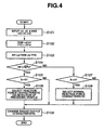
Fig. 4 . In the embodiment, the microprocessor repeats execution of a control routine at regular intervals of, for example, 50 milliseconds. - In
Fig. 4 , at step S101, the microprocessor performs a reading operation of the output of the scene recognition device (radar device 10, vehicle speed sensor 30), and thestroke sensor 70 to receive, as inputs, a vehicle speed v1, a vehicle speed v2 of the preceding vehicle, if available, a distance d to the preceding vehicle, a relative speed vr between the vehicles, and a position S of theaccelerator pedal 81. - At step S102, the microprocessor determines a time headway THW and a time to collision TTC between the vehicle and the preceding vehicle by using the
equations 1 and 2 described above. - At step S103, the microprocessor determines a risk RP by using the equation 3.
- At step S104, the microprocessor determines whether or not the determined risk RP is greater than a predetermined value RP0. If this is the case (RP > RP0), the microprocessor recognizes that the determined risk should be transmitted to the driver and proceeds to determine, at step S105, whether or not the
accelerator pedal 81 is released by checking if the position S is zero. If this is not the case (RP ≤ RP0), the microprocessor proceeds to determine, at step S107, whether or not theaccelerator pedal 81 is released by checking if the position S is zero. - Once it has determined, at step S105, that the
accelerator pedal 81 is released, the microprocessor proceeds to select, at step S106, the accelerator pedal reaction force characteristic (see the one-dot chain line inFig. 5 ) that is appropriate to the environment involving detection of the preceding vehicle. Once this characteristic has been selected at step S106 and a switch to this characteristic has been completed by engaging the electromagnetically operated clutch 61, the microprocessor proceeds from step S105 directly to step S109. - Engaging the electromagnetically operated clutch 61 allows both of the first and
second springs - In
Fig. 5 , as readily seen from the illustrated one-dot chain line in comparison with the solid line, the two different accelerator pedal reaction force characteristics are different from each other in the absolute value of reaction force F over a portion of the whole range of different positions S of theaccelerator pedal 81. Over the portion of the whole range of different position S of theaccelerator pedal 81, the two different accelerator pedal reaction force characteristics are different from each other in a change in reaction force F per unit change in position of the accelerator. - With continuing reference to
Fig. 5 , over the portion of the whole range of different positions S of the accelerator pedal, the one-dot chain line drawn characteristic provides increased absolute value in reaction force F at each position S of theaccelerator pedal 81. Thus, the driver feels this increased reaction force via theaccelerator pedal 81. Over the portion of the whole range of different positions S of theaccelerator pedal 81, the one-dot chain line drawn characteristic also provides a higher increase in reaction force F per unit increase in position S of theaccelerator pedal 81. Thus, the driver feels greater increase in reaction force F upon depressing theaccelerator pedal 81. Via such tactile or haptic inputs, the presence of substantial risk RP is transmitted to the driver. - Once it has determined, at step S107, that the
accelerator pedal 81 is released, the microprocessor proceeds to select, at step S108, normal accelerator pedal reaction force characteristic (see the solid line inFig. 5 ). Once this characteristic has been selected at step S108 and a switch to this characteristic has been completed by disengaging the electromagnetically operated clutch 61, the microprocessor proceeds from step S107 directly to step S109. - As mentioned in connection with steps S105 and S107, the switch between the two different characteristics is prohibited when the driver depresses the
accelerator pedal 81. Unintentional driver's manipulation of theaccelerator pedal 81 due to a change in reaction force is prevented. - At step S109, the microprocessor changes the engine output characteristic in response to the determined risk RP at step S103. In
Fig. 6 , the solid line indicates the normal engine output characteristic that is selected upon detection of no preceding vehicle. According to this characteristic, the engine output is proportional to the position S of theaccelerator pedal 81. After detection of the preceding vehicle, as shown by the one-dot chain lines, a threshold value Sa, at which the engine output begins to appear, shifts in a direction of increasing the position S of theaccelerator pedal 81 as the determined risk RP increases. InFig. 6 , the illustrated one-dot chain lines show modified engine output characteristics. Since no engine output is produced until the driver depressed theaccelerator pedal 81 down to the threshold value Sa, there is an increasing play of theaccelerator pedal 81 as the risk RP increases. - With continuing reference to
Fig. 6 , a change in engine output per unit increase in position of theaccelerator pedal 81 increases as the risk RP increases. As shown inFig. 6 , the engine output characteristic is common at positions of theaccelerator pedal 81 exceeding a predetermined value Sb. - If the determined risk RP decreases, the engine output characteristic needs to shift toward the solid normal engine output characteristic. Gradual shift is preferred using, for example, a first-order delay filter. However, it the
accelerator pedal 81 is released, a quick return to the solid normal engine output characteristic may be allowed. - The
engine controller 91 controls an engine power control element, for example, a throttle valve, to regulate operation of the engine for production of an engine output characteristic of varying of engine output with the different positions S of theaccelerator pedal 81. - With reference now to
Figs. 6 and7 , if now the accelerator pedal reaction force as indicated by the one-dot chain line is provided upon or after the risk has exceeded the predetermined value RP0, there is an increase in reaction force F at the position S1 of theaccelerator pedal 81. In addition to this increase in reaction force F, a shortage in engine output for this position S1 is felt by the driver because the engine output characteristic has been modified in response to the risk RP to provide less engine output for the same position S of theaccelerator pedal 81. The increase in reaction force F in combination with the shortage in engine output makes an effective input to transmit the presence of the risk RP to the driver. The shortage in engine output prompts the driver to depressing theaccelerator pedal 81 deeply to a new position S2 to maintain the engine output to the previous level. In addition to an increase in reaction force F to the driver's effort to keep theaccelerator pedal 81 at the position S2, an amplified increase in reaction force F per an increase to the new position S2 must be overcome by the driver during a transient period. The increase in reaction force F in combination with the amplified increase in reaction force F during the transient period makes a more effective input to transmit the presence of the risk RP to the driver. - With the same position S maintained, a reduction in engine output causes the driver to feel deceleration, providing an effective input to transmit the presence of the risk RP to the driver.
- The embodiment according to the present invention provides the effects as follows:
- (1) An increase in reaction force F in combination with a deceleration feel caused due to a shortage in engine output provide an effective input to transmit the presence of risk RP in the environment around the vehicle. It is appreciated that, with a relatively economical construction, the presence of risk RP is effectively transmitted to the driver.
- (2) After switching in reaction force characteristic upon or after the risk RP has exceeded the predetermined value RP0, not only an increase in absolute value in reaction force F, but also an amplified increase in reaction force F per unit increase in accelerator pedal position S is provided. One or both of them make an effective input to transmit the presence of risk RP to the driver.
- (3) Switching in reaction force characteristic upon or after the risk RP has exceeded the predetermined value RP0 itself makes a clear input to transmit to the driver that reaction force control has started as scheduled.
- (4) Switching in reaction force characteristic is prohibited unless the driver has released the accelerator pedal. This is effective in preventing occurrence of unintentional change in engine output upon manipulation of the accelerator pedal, which might be caused due to an increase or decrease in reaction force.
- (5) Before the risk RP will exceed the predetermined value RP0, the engine output characteristic is modified in response to the risk RP, producing a deceleration feel to transmit the presence of risk (RP) within the environment around the vehicle.
- (6) As shown in
Figs. 3(a) and 3(b) , the use of the electromagnetically operated clutch 61 and thetensile spring 65 have eliminated use of an expensive motor and its complicated motor control circuit. Use of such components is appreciated as advantageous. - The reaction force characteristic indicated by the one-dot chain line in
Figs. 5 and7 is just one of various examples used in the embodiment according to the present invention. Another example is the use of different accelerator pedal reaction force characteristics that are different from each other in the absolute value of reaction force over at least a portion of the whole range of different positions of the accelerator. Another example is the use of different accelerator pedal reaction force characteristics that are different from each other in a change in reaction force per unit change in position of the accelerator pedal over at least a portion of the whole range of the different positions of the accelerator pedal. -
Fig. 8 shows another example of the accelerator pedal reaction force characteristics. - In
Fig. 8 , the one-dot chain line drawn characteristic is selected upon or after the determined risk RP has exceeded the predetermined value RP0. This reaction force characteristic produces a first small increase in reaction force F per unit increase in position of theaccelerator pedal 81 over a first portion, below a position Sc, of the whole range of the different positions of the accelerator pedal and a second large increase in reaction force F per unit increase in position S of the accelerator pedal over a second portion, in excess of the position Sc, of the whole range of the different positions S of theaccelerator pedal 81. With this characteristic, the accelerator pedal reaction force F slowly increases in the same manner as the fully drawn normal reaction force characteristic until the position S of theaccelerator pedal 81 reaches the predetermined value Sc. Once theaccelerator pedal 81 is depressed further deeply beyond the predetermined value Sc, the reaction force F increases quickly. - The modified engine output characteristics variable with the risk RP are designed such that, at the predetermined position Sc, the most appropriate engine output is produced to follow the preceding vehicle. With this setting of the modified engine output characteristic, the driver may easily keep the position S of the accelerator pedal at the predetermined position Sc, at which the most appropriate engine output is produced for the vehicle to follow the preceding vehicle.
- The one-dot chain line drawn characteristic may be realized by using a non-linear spring as the second
tensile spring 65 or by additionally providing a third spring. Such third spring is connected to thepedal 81 via an appropriate slide mechanism. The slide starts sliding when theaccelerator pedal 81 is depressed deeply beyond the predetermined value Sc to apply spring force of the third spring to thepedal 81. - According to the illustrated accelerator pedal reaction force characteristic, the driver is allowed to depress the
accelerator pedal 81 within a region (S < Sc), but discouraged to depress theaccelerator pedal 81 within another region (S ≥ Sc). By modifying the engine output characteristic to produce the most appropriate engine output for the vehicle to follow the preceding vehicle at the predetermined position Sc, it is possible to realize a vehicle characteristic that allows the driver to follow the preceding vehicle only by keeping the accelerator pedal at the predetermined position Sc as directed by the difference in reaction force. - In order to provide different characteristics of reaction force, two different springs may be connected to the
accelerator pedal 81 alternately. - The two
rotary shafts - In the preceding embodiment, the
laser radar 10 and thevehicle speed sensor 30 function as the scene recognition device. The scene recognition device is not limited to this example. Another example is the use of a millimeter wave frequency modulated continuous (FMCW) radar and/or a CCD camera and/or a MOS camera instead of thelaser radar 10. - In the preceding embodiment, the
controller 50 functions as the control logic determining risk based on the detected state of environment around the vehicle. - In the preceding embodiment, the
control logic 60 determines which one out of different accelerator pedal reaction force characteristics as shown, for example, inFig 5 or7 or 8 , theaccelerator pedal unit 80 should select and produce. It is appreciated that thecontrol logic 60 is responsible for a shift in accelerator pedal reaction force characteristic. It is to be noted that thecontrol logic 60 is not limited to the software implementation. Thecontrol logic 60 may be implemented in hardware in the form of a device, namely, an accelerator pedal reaction force shifting device. - In the preceding embodiment, the
control logic 90 selects one of data of different engine output characteristics and theengine controller 91 regulates operation of the engine to accomplish the selected engine output characteristic. It is appreciated that thecontrol logic 90 modifies operation of theengine controller 91 to modify the engine output characteristic. It is to be noted that thecontrol logic 90 is not limited to the software implementation. Thecontrol logic 90 may be implemented in hardware in the form of a device, namely, an engine output characteristic modifying device. - In the preceding embodiment, the
stroke sensor 70 is used to detect amount of driver's manual operation of theaccelerator pedal 81. The sensor is not limited to thestroke sensor 70. Another sensor may be used instead of thestroke sensor 70 to detect the amount of driver's manual operation of theaccelerator pedal 81. - The present invention is not limited to selection of one of two accelerator pedal reaction characteristics. Three different reaction force characteristics may be made by using more than two springs having different spring characteristics.
- In modifying the engine output characteristic, it is possible to modify the characteristic in response to a relative speed between the vehicle and the preceding vehicle and/or a distance to the preceding vehicle. For example, an increase in engine output per an unit accelerator pedal position S is suppressed as the absolute value of the relative speed vr increases and/or the distance becomes short. In this manner, the relationship between the vehicle and the preceding vehicle may be expressed by the relative speed vr and/or the distance d instead of the risk RP.
- While the best modes for carrying out the invention have been described in detail, those familiar with the art to which the present invention relates will recognize various alternative designs and embodiments for practicing the invention as defined by the following claims.
Claims (13)
- A system for assisting a driver operating a vehicle traveling on a road, the system comprising:- an engine controller (50, 90, 91) regulating operation of an engine of the vehicle to provide a desired engine output characteristic; a control logic (50, 60, 90) including a first control section (50) that determines the risk based on the detected state of the environment around the vehicle said control logic (50, 60, 90) controlling the engine controller (50, 90, 91) to modify the engine output characteristic in response to at least one of a detected state of an environment around the vehicle and a determined risk;characterized by- an accelerator (50, 60, 80) having different positions and selectively producing different acceleration reaction force characteristics, each different acceleration reaction force characteristic providing varying of reaction force with different positions of the accelerator, and- a second control section (60) that controls the accelerator (50, 60, 80) to select one of the different accelerator reaction force characteristics, each different accelerator reaction force characteristic varying the reaction force with different positions of the accelerator (50, 60, 80);- wherein the engine output characteristic relates on varying of the engine output with the different positions of the accelerator (50, 60, 80).
- The system as recited in claim 1, further comprising a scene recognition device (10) detecting the state of the environment around the vehicle.
- The system as recited in claim 1, wherein the different accelerator reaction force characteristics are different from each other in the absolute value of reaction force over at least a portion of the whole range of different positions of the accelerator.
- The system as recited in claim 1, wherein the different accelerator reaction force characteristics are different from each other in a change in reaction force per unit change in position of the accelerator (50, 60, 80) over at least a portion of the whole range of the different positions of the accelerator.
- The system as recited in claim 1, wherein the second control section causes the accelerator (80) to select one of the different accelerator reaction force characteristics upon determination that an obstacle exists in front of the vehicle within the environment around the vehicle.
- The system as recited in claim 1, wherein the second control section causes the accelerator (50, 60, 80) to select one of the different accelerator reaction force characteristics upon determination that the risk is greater than a predetermined value.
- The system as recited in claim 1, wherein the second control section causes the accelerator (50, 60, 80) to select one of the different accelerator pedal reaction force upon determination that the accelerator pedal has been released.
- The system as recited in claim 1, wherein, regardless of operation of the second control section, the control logic modifies the engine output characteristic in response to at least one of the detected state of environment and the determined risk.
- The system as recited in claim 1, wherein at least one of the different reaction force characteristics produces a first change in reaction force per unit change in position of the accelerator (50, 60, 80) over a first portion of the whole range of the different positions of the accelerator and a second change in reaction force per unit change in position of the accelerator (50, 60, 80) over a second portion of the whole range of the different positions of the accelerator.
- The system as recited in claim 1, wherein the control logic modifies the engine output characteristic based on a relative vehicle speed between the vehicle and an obstacle in front of the vehicle.
- The system as recited in claim 1, wherein the accelerator (50, 60, 80) has an accelerator pedal (81) with a plurality of springs (65, 85) that act on the accelerator pedal (81) to realize the different reaction force characteristics.
- The system is recited in claim 1, wherein the control logic modifies the engine output characteristic in relation to the accelerator position such that the greater the determined risk, the lesser the engine output for a given accelerator position.
- A method for assisting a driver operating a vehicle by manipulating an accelerator (50, 60, 80) having different positions, the method comprising:- detecting a state of an environment around the vehicle;- determining the risk based on the detected state of the environment around the vehicle by a first control section included in a control logic,characterized by- a regulating operation of an engine of the vehicle to provide an engine output characteristic of varying of engine output with different positions of the accelerator;- a modifying operation of the engine controller (50, 90, 91) to modify the engine output characteristic in response to at least one of the detected state of environment and the determined risk,- controlling the accelerator (50, 60, 80) to select one of the different accelerator reaction force characteristics, each different accelerator reaction force characteristic varying the reaction force with different positions of the accelerator (50, 60, 80) by a second control section included in the control logic,- wherein the engine output characteristic relates on varying of the engine output with the different positions of the accelerator (80).
Applications Claiming Priority (2)
| Application Number | Priority Date | Filing Date | Title |
|---|---|---|---|
| JP2004069514A JP3956948B2 (en) | 2004-03-11 | 2004-03-11 | VEHICLE DRIVE OPERATION ASSISTANCE DEVICE AND VEHICLE HAVING VEHICLE DRIVE OPERATION ASSISTANCE DEVICE |
| JP2004069514 | 2004-03-11 |
Publications (3)
| Publication Number | Publication Date |
|---|---|
| EP1574384A2 EP1574384A2 (en) | 2005-09-14 |
| EP1574384A3 EP1574384A3 (en) | 2006-04-26 |
| EP1574384B1 true EP1574384B1 (en) | 2008-11-26 |
Family
ID=34824611
Family Applications (1)
| Application Number | Title | Priority Date | Filing Date |
|---|---|---|---|
| EP05003694A Expired - Lifetime EP1574384B1 (en) | 2004-03-11 | 2005-02-21 | System and method assisting a vehicle driver via changes in accelerator reaction force and engine output characteristic |
Country Status (4)
| Country | Link |
|---|---|
| US (1) | US7715969B2 (en) |
| EP (1) | EP1574384B1 (en) |
| JP (1) | JP3956948B2 (en) |
| DE (1) | DE602005011194D1 (en) |
Cited By (1)
| Publication number | Priority date | Publication date | Assignee | Title |
|---|---|---|---|---|
| US9156354B2 (en) | 2011-09-22 | 2015-10-13 | Knorr-Bremse Systeme Fuer Nutzfahrzeuge Gmbh | Driver assistance system having autonomous braking to a standstill |
Families Citing this family (13)
| Publication number | Priority date | Publication date | Assignee | Title |
|---|---|---|---|---|
| JP3960317B2 (en) * | 2004-03-03 | 2007-08-15 | 日産自動車株式会社 | VEHICLE DRIVE OPERATION ASSISTANCE DEVICE AND VEHICLE WITH VEHICLE DRIVE OPERATION ASSISTANCE DEVICE |
| DE102004033487B4 (en) * | 2004-07-10 | 2006-03-16 | Bayerische Motoren Werke Ag | Device for generating a haptic signal in a vehicle |
| JP4543908B2 (en) | 2004-12-07 | 2010-09-15 | 日産自動車株式会社 | VEHICLE DRIVE OPERATION ASSISTANCE DEVICE AND VEHICLE HAVING VEHICLE DRIVE OPERATION ASSISTANCE DEVICE |
| JP4943661B2 (en) * | 2005-03-31 | 2012-05-30 | 日立オートモティブシステムズ株式会社 | Pedal device and automobile equipped with the same |
| JP2007022238A (en) * | 2005-07-14 | 2007-02-01 | Nissan Motor Co Ltd | VEHICLE DRIVE OPERATION ASSISTANCE DEVICE AND VEHICLE WITH VEHICLE DRIVE OPERATION ASSISTANCE DEVICE |
| US20090326780A1 (en) * | 2006-08-16 | 2009-12-31 | Adc Automotive Distance Control Systems Gmbh | Method for distance control |
| US20090018723A1 (en) * | 2007-07-12 | 2009-01-15 | Dan Chevion | Driver/Vehicle Interface Combining Dynamic Function Modification of Vehicle Controls with Haptic Feedback |
| JP5439766B2 (en) * | 2007-10-23 | 2014-03-12 | 日産自動車株式会社 | Inter-vehicle maintenance support device and inter-vehicle maintenance support method |
| US9110490B2 (en) | 2011-08-31 | 2015-08-18 | Ksr Ip Holdings Llc. | Floor mount ETC pedal with integrated kickdown and tactile alert mechanisms |
| KR101406533B1 (en) * | 2013-04-16 | 2014-06-12 | 기아자동차주식회사 | Active control method of accelerator pedal effort |
| US9290094B2 (en) | 2014-04-01 | 2016-03-22 | Atieva, Inc. | Dual stage accelerator assembly with pedal feedback system |
| JP6347229B2 (en) * | 2015-05-14 | 2018-06-27 | トヨタ自動車株式会社 | Control device for hybrid vehicle |
| US10859682B2 (en) | 2017-12-07 | 2020-12-08 | Ouster, Inc. | Telematics using a light ranging system |
Family Cites Families (19)
| Publication number | Priority date | Publication date | Assignee | Title |
|---|---|---|---|---|
| JPS5733048A (en) | 1980-08-04 | 1982-02-23 | Honda Motor Co Ltd | Throttle reaction control device of car |
| JPS57167845A (en) | 1981-04-07 | 1982-10-15 | Honda Motor Co Ltd | Vehicle throttle reaction force control system |
| US4819163A (en) * | 1985-12-21 | 1989-04-04 | Toyota Jidosha Kabushiki Kaisha | Driving power control system |
| JPH03943A (en) | 1989-05-29 | 1991-01-07 | Aisin Seiki Co Ltd | Throttle control device |
| JP2907538B2 (en) * | 1990-11-30 | 1999-06-21 | 日産自動車株式会社 | Accelerator pedal device for vehicles |
| JPH10166889A (en) | 1996-12-04 | 1998-06-23 | Suzuki Motor Corp | Alarm device |
| JPH10166890A (en) | 1996-12-04 | 1998-06-23 | Suzuki Motor Corp | Alarm device |
| US6087942A (en) * | 1998-05-18 | 2000-07-11 | Jb Research, Inc. | Tactile alert and massaging system |
| US6259992B1 (en) * | 1998-06-03 | 2001-07-10 | Honda Giken Kogyo Kabushiki Kaisha | Vehicle safety running control system |
| JP2000052809A (en) | 1998-08-13 | 2000-02-22 | Mitsubishi Electric Corp | Abnormal approach prevention device |
| US6161071A (en) * | 1999-03-12 | 2000-12-12 | Navigation Technologies Corporation | Method and system for an in-vehicle computing architecture |
| US6945346B2 (en) * | 2000-09-28 | 2005-09-20 | Automotive Distance Control Systems Gmbh | Method for operating a driver support system for motor vehicles |
| JP4173292B2 (en) | 2001-08-23 | 2008-10-29 | 日産自動車株式会社 | Driving assistance device for vehicle |
| DE60226817D1 (en) | 2001-08-23 | 2008-07-10 | Nissan Motor | Driving Assistance System |
| DE10212674A1 (en) * | 2002-03-22 | 2003-10-02 | Daimler Chrysler Ag | Process and accelerating system to produce an adjustable retarding force in vehicle or electric vehicle, has a passive spring and an active force control |
| JP3613264B2 (en) * | 2002-06-18 | 2005-01-26 | 日産自動車株式会社 | Driving assistance device for vehicle |
| JP3838166B2 (en) * | 2002-06-20 | 2006-10-25 | 日産自動車株式会社 | Driving assistance device for vehicle |
| JP3700682B2 (en) * | 2002-06-20 | 2005-09-28 | 日産自動車株式会社 | Accelerator pedal device |
| JP4543908B2 (en) * | 2004-12-07 | 2010-09-15 | 日産自動車株式会社 | VEHICLE DRIVE OPERATION ASSISTANCE DEVICE AND VEHICLE HAVING VEHICLE DRIVE OPERATION ASSISTANCE DEVICE |
-
2004
- 2004-03-11 JP JP2004069514A patent/JP3956948B2/en not_active Expired - Lifetime
-
2005
- 2005-02-21 DE DE602005011194T patent/DE602005011194D1/en not_active Expired - Lifetime
- 2005-02-21 EP EP05003694A patent/EP1574384B1/en not_active Expired - Lifetime
- 2005-03-01 US US11/067,927 patent/US7715969B2/en active Active
Cited By (3)
| Publication number | Priority date | Publication date | Assignee | Title |
|---|---|---|---|---|
| US9156354B2 (en) | 2011-09-22 | 2015-10-13 | Knorr-Bremse Systeme Fuer Nutzfahrzeuge Gmbh | Driver assistance system having autonomous braking to a standstill |
| EP2758291B1 (en) | 2011-09-22 | 2017-11-15 | KNORR-BREMSE Systeme für Nutzfahrzeuge GmbH | Driver assistance system having autonomous braking to a standstill |
| DE102011114072C5 (en) * | 2011-09-22 | 2021-04-22 | Knorr-Bremse Systeme für Nutzfahrzeuge GmbH | Driver assistance system with autonomous braking to a standstill |
Also Published As
| Publication number | Publication date |
|---|---|
| US7715969B2 (en) | 2010-05-11 |
| DE602005011194D1 (en) | 2009-01-08 |
| EP1574384A3 (en) | 2006-04-26 |
| US20050222742A1 (en) | 2005-10-06 |
| JP3956948B2 (en) | 2007-08-08 |
| EP1574384A2 (en) | 2005-09-14 |
| JP2005258815A (en) | 2005-09-22 |
Similar Documents
| Publication | Publication Date | Title |
|---|---|---|
| US7162349B2 (en) | Driving assist system and method with accelerator pedal reaction force control | |
| US7228233B2 (en) | Driving assistance method and system | |
| EP1574384B1 (en) | System and method assisting a vehicle driver via changes in accelerator reaction force and engine output characteristic | |
| JP3871728B2 (en) | System and method for intelligent cruise control using standard engine control modes | |
| US6470257B1 (en) | Adaptive cruise control system for automotive vehicles | |
| US11208102B2 (en) | Adaptive cruise control | |
| KR100850412B1 (en) | Method and system for assisting a driver of a vehicle operating a vehicle traveling on a road | |
| US6223118B1 (en) | Vehicle deceleration control unit | |
| US6917872B2 (en) | Driving assist system for vehicle | |
| US7904245B2 (en) | Method and vehicle reacting to the detection of an in-path obstacle | |
| US20010008989A1 (en) | Method and apparatus for controller power train of motor vehicle | |
| EP2000380A9 (en) | Vehicle travel control device and vehicle travel control method | |
| US6327530B1 (en) | Apparatus and method for controlling a distance between two traveling vehicles and a recording medium for storing the control method | |
| US7689361B2 (en) | Driving operation assisting system, method and vehicle incorporating the system | |
| US7715972B2 (en) | Driving assisting system for a vehicle and a vehicle installed with the system | |
| EP1607262B1 (en) | Driving assistance method and system | |
| JP4424213B2 (en) | Vehicle control device | |
| US12179759B2 (en) | Vehicle control device | |
| JP7690886B2 (en) | Driving Support Devices | |
| JP2026026801A (en) | Driving control device | |
| JP2007056737A (en) | Accelerator control device |
Legal Events
| Date | Code | Title | Description |
|---|---|---|---|
| PUAI | Public reference made under article 153(3) epc to a published international application that has entered the european phase |
Free format text: ORIGINAL CODE: 0009012 |
|
| 17P | Request for examination filed |
Effective date: 20050221 |
|
| AK | Designated contracting states |
Kind code of ref document: A2 Designated state(s): AT BE BG CH CY CZ DE DK EE ES FI FR GB GR HU IE IS IT LI LT LU MC NL PL PT RO SE SI SK TR |
|
| AX | Request for extension of the european patent |
Extension state: AL BA HR LV MK YU |
|
| PUAL | Search report despatched |
Free format text: ORIGINAL CODE: 0009013 |
|
| AK | Designated contracting states |
Kind code of ref document: A3 Designated state(s): AT BE BG CH CY CZ DE DK EE ES FI FR GB GR HU IE IS IT LI LT LU MC NL PL PT RO SE SI SK TR |
|
| AX | Request for extension of the european patent |
Extension state: AL BA HR LV MK YU |
|
| AKX | Designation fees paid |
Designated state(s): DE FR GB |
|
| 17Q | First examination report despatched |
Effective date: 20070606 |
|
| GRAP | Despatch of communication of intention to grant a patent |
Free format text: ORIGINAL CODE: EPIDOSNIGR1 |
|
| GRAS | Grant fee paid |
Free format text: ORIGINAL CODE: EPIDOSNIGR3 |
|
| GRAA | (expected) grant |
Free format text: ORIGINAL CODE: 0009210 |
|
| AK | Designated contracting states |
Kind code of ref document: B1 Designated state(s): DE FR GB |
|
| REG | Reference to a national code |
Ref country code: GB Ref legal event code: FG4D |
|
| REF | Corresponds to: |
Ref document number: 602005011194 Country of ref document: DE Date of ref document: 20090108 Kind code of ref document: P |
|
| PLBE | No opposition filed within time limit |
Free format text: ORIGINAL CODE: 0009261 |
|
| STAA | Information on the status of an ep patent application or granted ep patent |
Free format text: STATUS: NO OPPOSITION FILED WITHIN TIME LIMIT |
|
| 26N | No opposition filed |
Effective date: 20090827 |
|
| REG | Reference to a national code |
Ref country code: FR Ref legal event code: PLFP Year of fee payment: 12 |
|
| REG | Reference to a national code |
Ref country code: FR Ref legal event code: PLFP Year of fee payment: 13 |
|
| REG | Reference to a national code |
Ref country code: FR Ref legal event code: PLFP Year of fee payment: 14 |
|
| REG | Reference to a national code |
Ref country code: DE Ref legal event code: R084 Ref document number: 602005011194 Country of ref document: DE |
|
| REG | Reference to a national code |
Ref country code: GB Ref legal event code: 746 Effective date: 20231002 |
|
| PGFP | Annual fee paid to national office [announced via postgrant information from national office to epo] |
Ref country code: DE Payment date: 20240123 Year of fee payment: 20 Ref country code: GB Payment date: 20240123 Year of fee payment: 20 |
|
| PGFP | Annual fee paid to national office [announced via postgrant information from national office to epo] |
Ref country code: FR Payment date: 20240123 Year of fee payment: 20 |
|
| REG | Reference to a national code |
Ref country code: DE Ref legal event code: R071 Ref document number: 602005011194 Country of ref document: DE |
|
| REG | Reference to a national code |
Ref country code: GB Ref legal event code: PE20 Expiry date: 20250220 |
|
| PG25 | Lapsed in a contracting state [announced via postgrant information from national office to epo] |
Ref country code: GB Free format text: LAPSE BECAUSE OF EXPIRATION OF PROTECTION Effective date: 20250220 |