EP1574304A1 - Bread slicer with knives arranged in a wave- or v-shape. - Google Patents
Bread slicer with knives arranged in a wave- or v-shape. Download PDFInfo
- Publication number
- EP1574304A1 EP1574304A1 EP04075770A EP04075770A EP1574304A1 EP 1574304 A1 EP1574304 A1 EP 1574304A1 EP 04075770 A EP04075770 A EP 04075770A EP 04075770 A EP04075770 A EP 04075770A EP 1574304 A1 EP1574304 A1 EP 1574304A1
- Authority
- EP
- European Patent Office
- Prior art keywords
- knives
- mentioned
- bread
- constructed
- supporting frame
- Prior art date
- Legal status (The legal status is an assumption and is not a legal conclusion. Google has not performed a legal analysis and makes no representation as to the accuracy of the status listed.)
- Granted
Links
Images


Classifications
-
- B—PERFORMING OPERATIONS; TRANSPORTING
- B26—HAND CUTTING TOOLS; CUTTING; SEVERING
- B26D—CUTTING; DETAILS COMMON TO MACHINES FOR PERFORATING, PUNCHING, CUTTING-OUT, STAMPING-OUT OR SEVERING
- B26D1/00—Cutting through work characterised by the nature or movement of the cutting member or particular materials not otherwise provided for; Apparatus or machines therefor; Cutting members therefor
- B26D1/01—Cutting through work characterised by the nature or movement of the cutting member or particular materials not otherwise provided for; Apparatus or machines therefor; Cutting members therefor involving a cutting member which does not travel with the work
- B26D1/547—Cutting through work characterised by the nature or movement of the cutting member or particular materials not otherwise provided for; Apparatus or machines therefor; Cutting members therefor involving a cutting member which does not travel with the work having a wire-like cutting member
- B26D1/553—Cutting through work characterised by the nature or movement of the cutting member or particular materials not otherwise provided for; Apparatus or machines therefor; Cutting members therefor involving a cutting member which does not travel with the work having a wire-like cutting member with a plurality of wire-like cutting members
-
- B—PERFORMING OPERATIONS; TRANSPORTING
- B26—HAND CUTTING TOOLS; CUTTING; SEVERING
- B26D—CUTTING; DETAILS COMMON TO MACHINES FOR PERFORATING, PUNCHING, CUTTING-OUT, STAMPING-OUT OR SEVERING
- B26D7/00—Details of apparatus for cutting, cutting-out, stamping-out, punching, perforating, or severing by means other than cutting
- B26D7/26—Means for mounting or adjusting the cutting member; Means for adjusting the stroke of the cutting member
- B26D7/2614—Means for mounting the cutting member
Definitions
- the present invention relates to a device for cutting loafs and other mainly spacial products into slices, mostly in order to offer the sliced bread packed to the client, in which in the mentioned device specially constructed blades are mounted, in which supporting and guiding plates or means for slicing loafs or breads have been applied, in which the mentioned loaf or bread is moved with a pusher towards a number of oscillating or moving cutting instruments with an approximate equal mutual distance and placed transverse on the bread, in which the mentioned distances between the cutting instruments is done in such a way to allow compression compensation, in which the movement or the oscillating movement in the longitudinal axis of the mentioned cutting instrument is done by means of a special driving mechanism, in which the whole is mostly provided with a housing to protect the user, in which an intake and outlet opening is included.
- a somewhat similar device is known e.g. from the American Patent document US 1 975 942, titled: "Bread Slicer", of HARTMAN, William, Walter, Los Angeles, California. Patent is issued on 09-10-1934. Here, it concerns a cutting mechanism for bread slicers.
- a cutting head consists of multiple lateral, at a distance placed knives in parallel planes, in which at one side the knives are connected to a crankshaft and at the other side are tensioned with draw springs in a rimmed stretcher, which must be constructed rather heavily due to the many springs.
- the drawing springs on the top side of the knives are suspended in a blunt V-shape, through which the knives start cutting the bread practically at the same time, but first the outer knives and then step by step inwardly the next pairs of knives are used, through which the bread is not pulled apart.
- the mentioned V-shape is achieved singularly over the whole length of the loaf or bread, through which the staggering of the knives, also due to the very blunt inner angle, is very small and in which the knife staggering is not completely used.
- the set-up of the knives shows an almost complete overlap, through which a high compression is created on the loaf per slice. Actually the knives form half a cone and due to the crankshaft only one cone with a very small top angle is possible.
- the thin knives will start vibrating sooner and due to the tension of the springs of a large quantity of drawing springs a lot of energy is necessary to keep the device going to cut through the loaf or bread. Further, the exerted pressure of the pusher cannot be too high because the knives almost simultaneously cut into the loaf or bread, through which the resistance is large due to the cutting and the slices are crushed together. This is not beneficial for a beautiful result of the sliced bread.
- the knives are mostly placed in almost an overlapping row.
- the knives which are tensioned with a spring load of approximately 200 to 400 N and depending on the make of the slicer, have a varied thickness of 0,4 en 0,5 mm, an average of 0,45 mm, in which they are sharpened double sided.
- For the compression of the bread with a length of 400 mm and a required slice thickness of approximately 10 mm, can be determined with a usual thickness of the knives of 0,45 mm, e.g. In this case 400:10 40 knives with a thickness of 0,45 mm are active.
- the aim of the present invention concerns to provide a bread slicer, which has a number of advantages in relation to the above described bread slicers, in which the knives play an important role and which knives are not suspended spring tensioned.
- the aimed advantages concern a larger speed overlap of the knives, a lighter construction by avoiding the needed heavy stretcher and therefore less vibrations and wear and finally a much smaller exertion of force of the knives as total set exerted on the loaf, by providing a step by step cutting of the bread and that it is minimally pushed together lengthwise, by sharpening the knives in a suitable way and placing the sharpened knives in a certain manner in the double oscillating supporting frame.
- the aim of the present invention is to provide a very efficient bread slicer, which has a light construction, minimally crunches and/or damages the bread, needs little driving power and in which the knives can easily be changed and the reversely placed knives are still useable. Further, sharpening such knives should be as cheap as possible.
- a bread slicer according to the invention is developed in a very inventive way, characterized in that, the mentioned oscillated driven cutting instrument is constructed of two sets of reciprocal driven rigidly restrained specially constructed knives, which in top view on one side are mounted in a saw-tooth shape placeable in various layers constructed in a wave- or V-shape alternating in a first or a second supporting frame, in which the set-up of the knifes does not show a mutual overlap, in which the first and the second supporting frames move the mentioned phase shifted sets of knifes oscillating in their longitudinal axis.
- knives which are sufficiently thick and broad, knives are created which are sufficiently rigid to prevent tensioning and bending. This means, that the knives are fixed and driven on one end. Through the other end of the knife only a guide is applied.
- the chosen thickness of the knives lies between 0,6 and 3 mm.
- the width of the knives lies preferably between 5 and 15 mm.
- the device according to the invention is further developed, characterized in that, the mentioned rigidly restrained knives are rigidly fixed in the mentioned supporting frame on one end and on the other end oscillate in a slotted guiding construction, in which both ends of the knives are constructed as reversible use useable, and in which the mentioned knives are sharpened on one side.
- the advantages are a fast changing of the knives and minimum deformation of the bread.
- the device according to the invention is further developed, characterized in that, the mentioned saw-tooth shaped set-up of the knives in a first or second supporting frame, wherein the supporting frames are driven in such a way that they mutually are moving in a reciprocal oscillating way with an eccentric gear, in which the set-up knives are sharpened per pair in one layer facing each other.
- the supporting frames 6 and 7 are enlarged.
- the supporting frame 7 has a bush construction 22 and axis 23.
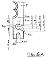
- Figure 6A shows in top view the end 24 with a knife 5 with a first preferred embodiment or concept of the attachment recesses 25, 26 for the means 9, 10 of the previous figures 3, 4, 5.
- Figures 6B and 6C show a second embodiment or concept of the ends of the knives 5' with the same cutting profile as knives 5, but with another attachment recess 27 for fixing into the supporting frames 6 and 7, which is done with a bent away laminated suspension spring 28 and which bent away laminated suspension spring 28 can be unlocked with a special unlocking pin 29.
- the bent away laminated suspension spring 28 locks the knives 5'.
- the knives 5' can be placed in a very simple way and can be removed with an unlocking pin 29 to be placed. The extreme position of the unlocking pin 29 is against knife 5' and with that it is avoided, that the laminated suspension spring 28 is pulled further than its elastic permissible stress.
- Figure 7 schematically shows the set-up of the knives in layers and the single sided sharpened direction of the knives, in which the reciprocal movement of the knives 5', 5 is indicated per pair, in which, for example, the knives 5', 5 with a + are moved upwards and the knives with a - are moved downwards at the same time.
Abstract
Description
- The present invention relates to a device for cutting loafs and other mainly spacial products into slices, mostly in order to offer the sliced bread packed to the client, in which in the mentioned device specially constructed blades are mounted, in which supporting and guiding plates or means for slicing loafs or breads have been applied, in which the mentioned loaf or bread is moved with a pusher towards a number of oscillating or moving cutting instruments with an approximate equal mutual distance and placed transverse on the bread, in which the mentioned distances between the cutting instruments is done in such a way to allow compression compensation, in which the movement or the oscillating movement in the longitudinal axis of the mentioned cutting instrument is done by means of a special driving mechanism, in which the whole is mostly provided with a housing to protect the user, in which an intake and outlet opening is included.
- A somewhat similar device is known e.g. from the American Patent document US 1 975 942, titled: "Bread Slicer", of HARTMAN, William, Walter, Los Angeles, California. Patent is issued on 09-10-1934. Here, it concerns a cutting mechanism for bread slicers. A cutting head consists of multiple lateral, at a distance placed knives in parallel planes, in which at one side the knives are connected to a crankshaft and at the other side are tensioned with draw springs in a rimmed stretcher, which must be constructed rather heavily due to the many springs. The drawing springs on the top side of the knives are suspended in a blunt V-shape, through which the knives start cutting the bread practically at the same time, but first the outer knives and then step by step inwardly the next pairs of knives are used, through which the bread is not pulled apart. The mentioned V-shape is achieved singularly over the whole length of the loaf or bread, through which the staggering of the knives, also due to the very blunt inner angle, is very small and in which the knife staggering is not completely used. The set-up of the knives shows an almost complete overlap, through which a high compression is created on the loaf per slice. Actually the knives form half a cone and due to the crankshaft only one cone with a very small top angle is possible. Due to the mentioned crankshaft and the V-shaped set-up of the drawing springs, the thin knives will start vibrating sooner and due to the tension of the springs of a large quantity of drawing springs a lot of energy is necessary to keep the device going to cut through the loaf or bread. Further, the exerted pressure of the pusher cannot be too high because the knives almost simultaneously cut into the loaf or bread, through which the resistance is large due to the cutting and the slices are crushed together. This is not beneficial for a beautiful result of the sliced bread.
- The above described solution for a bread slicer has a number of disadvantages, such as the heavy frames, the relatively large driving power to move the knives with drawing springs up and down and to move the compressed slices between the mutual overlapping knives by means of friction and next also the driving power for the pusher, which also leads to vibrations.
- Further, research has shown that the set-up of the knives and the construction thereof has a large influence on the compression of, for example, cutting a bread and has further consequences, as shown hereafter.
- In the known bread slicers the knives are mostly placed in almost an overlapping row. The knives, which are tensioned with a spring load of approximately 200 to 400 N and depending on the make of the slicer, have a varied thickness of 0,4 en 0,5 mm, an average of 0,45 mm, in which they are sharpened double sided. For the compression of the bread with a length of 400 mm and a required slice thickness of approximately 10 mm, can be determined with a usual thickness of the knives of 0,45 mm, e.g. In this case 400:10=40 knives with a thickness of 0,45 mm are active. Herewith, the whole bread is forced to compress 40×0,45mm=18mm. This compression has friction as the most important disadvantage, which develops between the knives and the bread due to the applied compression forces. The consequences are:
- wear of the knives;
- crumbling;
- sticking of the bread on the knives when the bread is still warm and/or sticky;
- pulling the bread apart between two knives moving in a different direction;
- when the feed or push speed (pusher speed) of the bread is too fast, the bread is compressed, in which the slices are permanently deformed or even broken.
- Further, the tension of the known knives of 200 to 400 Newton leads to a large bending moment in the stretcher, which leads to large dimensions and has disadvantages regarding the dynamic behaviour of the bread slicer.
- The aim of the present invention concerns to provide a bread slicer, which has a number of advantages in relation to the above described bread slicers, in which the knives play an important role and which knives are not suspended spring tensioned. The aimed advantages concern a larger speed overlap of the knives, a lighter construction by avoiding the needed heavy stretcher and therefore less vibrations and wear and finally a much smaller exertion of force of the knives as total set exerted on the loaf, by providing a step by step cutting of the bread and that it is minimally pushed together lengthwise, by sharpening the knives in a suitable way and placing the sharpened knives in a certain manner in the double oscillating supporting frame.
- In short, the aim of the present invention is to provide a very efficient bread slicer, which has a light construction, minimally crunches and/or damages the bread, needs little driving power and in which the knives can easily be changed and the reversely placed knives are still useable. Further, sharpening such knives should be as cheap as possible.
- In order to achieve the abovementioned aim, respectively advantages, a bread slicer according to the invention is developed in a very inventive way, characterized in that, the mentioned oscillated driven cutting instrument is constructed of two sets of reciprocal driven rigidly restrained specially constructed knives, which in top view on one side are mounted in a saw-tooth shape placeable in various layers constructed in a wave- or V-shape alternating in a first or a second supporting frame, in which the set-up of the knifes does not show a mutual overlap, in which the first and the second supporting frames move the mentioned phase shifted sets of knifes oscillating in their longitudinal axis.
- The aim of minimum power, little vibrations and minimum damage to the bread or other object is achieved.
- By using knives which are sufficiently thick and broad, knives are created which are sufficiently rigid to prevent tensioning and bending. This means, that the knives are fixed and driven on one end. Through the other end of the knife only a guide is applied. The chosen thickness of the knives lies between 0,6 and 3 mm. The width of the knives lies preferably between 5 and 15 mm. By placing the single sided sharpened knives according to a certain configuration in different layers (wave or V-shape), the compression of the bread is herewith organized in such a way, that cutting the bread leads to a lower compression. Each two cooperating knives exert a reciprocal cutting movement.
- Further, the device according to the invention is further developed, characterized in that, the mentioned rigidly restrained knives are rigidly fixed in the mentioned supporting frame on one end and on the other end oscillate in a slotted guiding construction, in which both ends of the knives are constructed as reversible use useable, and in which the mentioned knives are sharpened on one side.
- The advantages are a fast changing of the knives and minimum deformation of the bread.
- Furthermore, the device according to the invention is further developed, characterized in that, the mentioned saw-tooth shaped set-up of the knives in a first or second supporting frame, wherein the supporting frames are driven in such a way that they mutually are moving in a reciprocal oscillating way with an eccentric gear, in which the set-up knives are sharpened per pair in one layer facing each other.
- The advantages are, that the pairs of knives always move reciprocal oscillating in relation to each other and that sharpening the knives on one side is much cheaper.
- The preferred construction of the invention will be described by way of example, and with reference to the accompanying drawing.
- In which:
- Fig. 1
- shows a schematic view in oblique projection of the set-up of the bread slicer according to a preferred embodiment of the invention;
- Fig. 2
- shows a side view of the bread slicer according to a preferred embodiment of the bread slicer applied in figure 1;
- Fig. 3
- shows a view in oblique projection of the preferred embodiment of the cutting mechanism and pusher of the bread slicer;
- Fig. 4
- shows a bottom view in oblique projection of the cutting mechanism of the bread slicer according to figure 3;
- Fig. 5
- shows a bottom view in oblique projection of the supporting frame with the knives according to the invention, in which the reciprocal movement of the supporting frame is clearly visible.
- Fig. 6A up to 6C
- show top views of the end of the knife for the usable fast fixing in the mentioned supporting frame of figure 5; and
- Fig. 7
- here, the reciprocal movement of the knives is shown schematically.
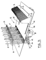
- Figure 1 schematically shows the set-
up 1 of a bread slicer with thecutting mechanism 2 andpusher 3. Further a guard 4 is applied over the cutting mechanism. - Figure 2 shows in side view the
cutting mechanism 2 at an angle α of approximately 60 degrees. Here, theknives 5', 5 are shown and how they are fixed in the supportingframes eccentric gear 8. Here, the reciprocal movement of theknives 5', 5 is clearly seen. The knives are herewith placed in a V-shape in 5 rows (see figures 7 and 8). - Figure 3 shows a view in oblique projection of the
preferred embodiment of the
cutting mechanism 2. In this figure it is clearly shown that theknives 5', 5 are fixed at the bottom side in the supportingframes pusher 3 can be moved over the supportingplate 12 with the bread on it (all at 60 degrees) towards theknives 5', 5. The moving mechanism (not indicated) with guidingslots pusher 3 is clearly shown in figure 4. The movement is done by means of an electromotor, which drives theguide block 16 along theaxis frame 6 for theknives 5', 5 moves with abush construction 19 along theaxis 20. This is done in the same way at the supportingframe 7. Theeccentric mechanism 8 with theeccentric rod 21 are clearly visible. - In figure 5 the supporting
frames frame 7 has abush construction 22 andaxis 23. - Figure 6A shows in top view the
end 24 with aknife 5 with a first preferred embodiment or concept of the attachment recesses 25, 26 for themeans 9, 10 of the previous figures 3, 4, 5. - Figures 6B and 6C show a second embodiment or concept of the ends of the knives 5' with the same cutting profile as
knives 5, but with anotherattachment recess 27 for fixing into the supportingframes suspension spring 28 and which bent away laminatedsuspension spring 28 can be unlocked with a special unlockingpin 29. During use, the bent away laminatedsuspension spring 28 locks the knives 5'. Thus, the knives 5' can be placed in a very simple way and can be removed with an unlockingpin 29 to be placed. The extreme position of the unlockingpin 29 is against knife 5' and with that it is avoided, that thelaminated suspension spring 28 is pulled further than its elastic permissible stress. - Figure 7 schematically shows the set-up of the knives in layers and the single sided sharpened direction of the knives, in which the reciprocal movement of the
knives 5', 5 is indicated per pair, in which, for example, theknives 5', 5 with a + are moved upwards and the knives with a - are moved downwards at the same time. - Further, it must be noted that the mutual distance of the
knives 5" can be reduced in such a way, that these lay against each other or can be joined together to asingle knife 5", which gives a double sharpened knife. The movement direction of the bread is indicated with arrow A. - Finally it has to be emphasized, that the above description constitutes preferred embodiments of the invention, but that further variations and modifications are still possible without departing the scope of this patent document.
Claims (10)
- Device for cutting loafs or breads and other mainly spacial products into slices, mostly in order to offer the sliced bread packed to the client, in which in the mentioned device specially constructed blades are mounted, in which supporting and guiding plates or means for slicing loafs or breads have been applied, in which the mentioned bread is moved with a pusher towards a number of oscillating or moving cutting instruments with an approximate equal mutual distance and placed transverse on the bread, in which the mentioned distances between the cutting instruments is done in such a way to allow compression compensation, in which the movement or the oscillating movement in the longitudinal axis of the mentioned cutting instrument is done by means of a special driving mechanism, in which the whole is mostly provided with a housing to protect the user, in which an intake and outlet opening is included, characterized in that, the mentioned oscillated driven cutting instrument is constructed of two sets of reciprocal driven rigidly restrained specially constructed knives (5', 5), which in top view on one side are mounted in a saw-tooth shape placeable in various layers constructed in a wave- or V-shape alternating in a first or a second supporting frame (6, 7), in which the set-up of the knifes does not show a mutual overlap, in which the first and the second supporting frames (6, 7) move the mentioned phase shifted sets of knifes (5', 5) oscillating in their longitudinal axis.
- Device as claimed in claim 1, characterized in that, the mentioned rigidly restrained knives (5', 5) are rigidly fixed in the mentioned supporting frame (6, 7) on one end and on the other end oscillate in a slotted guiding construction (11), in which both ends of the knives are constructed as reversible use useable.
- Device as claimed in claims 1 - 2, characterized in that, the mentioned knives (5', 5) are sharpened on one side.
- Device as claimed in claims 1 - 3, characterized in that, the mentioned saw-tooth shaped set-up of the knives (5', 5) in a first or second supporting frame (6, 7), wherein the supporting frames are driven in such a way that they mutually are moving in a reciprocal oscillating way.
- Device as claimed in claims 1 - 4, characterized in that, the set-up knives (5', 5) are sharpened per pair in one layer facing each other.
- Device as claimed in claims 4 and 5, characterized in that, each pair of knives making a cut at that moment are sharpened facing each other and each time the separate knife is mounted in the first or the second supporting frame (6, 7) and thus execute a reciprocal oscillating movement in relation to each other.
- Device as claimed in claim 6, characterized in that, the mentioned knives (5', 5) have a knurl, saw-tooth, smooth or another saw shape.
- Device as claimed in claim 7, characterized in that, in cross-section the mentioned knives (5', 5) have a blade thickness between 0,6 and 3 mm, a width between 5 and 15 mm and a knife length of approximately 300 mm.
- Device as claimed in claim 8, characterized in that, the material of the knives is blade steel or teflonized steel.
- Device as claimed in claim 6, characterized in that, the driving of the first and the second supporting frame (6, 7) is constructed by means of a balanced disc with an eccentric rod (21) connected with an eccentric mechanism (8)
Priority Applications (5)
| Application Number | Priority Date | Filing Date | Title |
|---|---|---|---|
| ES04075770T ES2273151T3 (en) | 2004-03-09 | 2004-03-09 | BREAD SLIDER WITH BLADES DISPLAYED IN V OR WAVE FORM. |
| DE602004002377T DE602004002377T2 (en) | 2004-03-09 | 2004-03-09 | Machine for cutting bread with wavy or V-shaped knives |
| AT04075770T ATE339280T1 (en) | 2004-03-09 | 2004-03-09 | MACHINE FOR CUTTING BREAD WITH WAVE OR V-SHAPED KNIVES |
| EP04075770A EP1574304B1 (en) | 2004-03-09 | 2004-03-09 | Bread slicer with knives arranged in a wave- or v-shape. |
| PL04075770T PL1574304T3 (en) | 2004-03-09 | 2004-03-09 | Bread slicer with knives arranged in a wave- or v-shape. |
Applications Claiming Priority (1)
| Application Number | Priority Date | Filing Date | Title |
|---|---|---|---|
| EP04075770A EP1574304B1 (en) | 2004-03-09 | 2004-03-09 | Bread slicer with knives arranged in a wave- or v-shape. |
Publications (2)
| Publication Number | Publication Date |
|---|---|
| EP1574304A1 true EP1574304A1 (en) | 2005-09-14 |
| EP1574304B1 EP1574304B1 (en) | 2006-09-13 |
Family
ID=34814337
Family Applications (1)
| Application Number | Title | Priority Date | Filing Date |
|---|---|---|---|
| EP04075770A Expired - Lifetime EP1574304B1 (en) | 2004-03-09 | 2004-03-09 | Bread slicer with knives arranged in a wave- or v-shape. |
Country Status (5)
| Country | Link |
|---|---|
| EP (1) | EP1574304B1 (en) |
| AT (1) | ATE339280T1 (en) |
| DE (1) | DE602004002377T2 (en) |
| ES (1) | ES2273151T3 (en) |
| PL (1) | PL1574304T3 (en) |
Cited By (7)
| Publication number | Priority date | Publication date | Assignee | Title |
|---|---|---|---|---|
| WO2008097178A1 (en) * | 2007-02-06 | 2008-08-14 | Epu Ag | Vegetable and fruit slicer and method for slicing |
| KR100869475B1 (en) | 2007-06-20 | 2008-11-19 | 유신단열 주식회사 | A cutting device for heat insulting glass wool |
| RU2483546C1 (en) * | 2010-10-08 | 2013-06-10 | Роллматик С.Р.Л. | Food products cutting machine |
| KR20180126298A (en) * | 2017-05-17 | 2018-11-27 | 한국생명공학연구원 | Brain tissue cutting device |
| EP3466622A1 (en) * | 2017-10-09 | 2019-04-10 | Freek Arie Herman | Bread cutting machine |
| CN111844150A (en) * | 2020-07-15 | 2020-10-30 | 芜湖韩大防伪科技有限公司 | Back pressing and cutting device for adhesive printing machine |
| CN114888877A (en) * | 2022-06-07 | 2022-08-12 | 西藏天虹科技股份有限责任公司 | Radix codonopsis slicing technology and device for processing |
Citations (5)
| Publication number | Priority date | Publication date | Assignee | Title |
|---|---|---|---|---|
| US1975942A (en) * | 1932-05-02 | 1934-10-09 | Hartman William Walter | Bread slicer |
| US2023362A (en) * | 1934-06-11 | 1935-12-03 | Theodore K Walma | Adjustable knife frame for bread-slicing machines |
| US2092276A (en) * | 1935-10-18 | 1937-09-07 | Israel C Gellman | Bread slicing machine |
| US2528853A (en) * | 1945-05-26 | 1950-11-07 | Us Slicing Machine Co Inc | Multiple reciprocating blade bread slicing machine |
| GB798883A (en) * | 1954-09-30 | 1958-07-30 | Mueller Josef | A reciprocating machine for cutting soft goods |
-
2004
- 2004-03-09 EP EP04075770A patent/EP1574304B1/en not_active Expired - Lifetime
- 2004-03-09 DE DE602004002377T patent/DE602004002377T2/en not_active Expired - Lifetime
- 2004-03-09 PL PL04075770T patent/PL1574304T3/en unknown
- 2004-03-09 AT AT04075770T patent/ATE339280T1/en not_active IP Right Cessation
- 2004-03-09 ES ES04075770T patent/ES2273151T3/en not_active Expired - Lifetime
Patent Citations (5)
| Publication number | Priority date | Publication date | Assignee | Title |
|---|---|---|---|---|
| US1975942A (en) * | 1932-05-02 | 1934-10-09 | Hartman William Walter | Bread slicer |
| US2023362A (en) * | 1934-06-11 | 1935-12-03 | Theodore K Walma | Adjustable knife frame for bread-slicing machines |
| US2092276A (en) * | 1935-10-18 | 1937-09-07 | Israel C Gellman | Bread slicing machine |
| US2528853A (en) * | 1945-05-26 | 1950-11-07 | Us Slicing Machine Co Inc | Multiple reciprocating blade bread slicing machine |
| GB798883A (en) * | 1954-09-30 | 1958-07-30 | Mueller Josef | A reciprocating machine for cutting soft goods |
Cited By (12)
| Publication number | Priority date | Publication date | Assignee | Title |
|---|---|---|---|---|
| WO2008097178A1 (en) * | 2007-02-06 | 2008-08-14 | Epu Ag | Vegetable and fruit slicer and method for slicing |
| JP2010517796A (en) * | 2007-02-06 | 2010-05-27 | イーピーユー・アーゲー | Vegetable and fruit slicer and method for slicing |
| AU2008213145B2 (en) * | 2007-02-06 | 2013-02-07 | EPU Holding AB | Vegetable and fruit slicer and method for slicing |
| US8739669B2 (en) | 2007-02-06 | 2014-06-03 | Epu Ag | Vegetable and fruit slicer and method for slicing |
| KR100869475B1 (en) | 2007-06-20 | 2008-11-19 | 유신단열 주식회사 | A cutting device for heat insulting glass wool |
| RU2483546C1 (en) * | 2010-10-08 | 2013-06-10 | Роллматик С.Р.Л. | Food products cutting machine |
| KR20180126298A (en) * | 2017-05-17 | 2018-11-27 | 한국생명공학연구원 | Brain tissue cutting device |
| EP3466622A1 (en) * | 2017-10-09 | 2019-04-10 | Freek Arie Herman | Bread cutting machine |
| NL2019688B1 (en) * | 2017-10-09 | 2019-04-17 | Arie Herman Freek | Bread cutting machine |
| US10695936B2 (en) | 2017-10-09 | 2020-06-30 | Freek Arie HERMAN | Bread cutting machine |
| CN111844150A (en) * | 2020-07-15 | 2020-10-30 | 芜湖韩大防伪科技有限公司 | Back pressing and cutting device for adhesive printing machine |
| CN114888877A (en) * | 2022-06-07 | 2022-08-12 | 西藏天虹科技股份有限责任公司 | Radix codonopsis slicing technology and device for processing |
Also Published As
| Publication number | Publication date |
|---|---|
| EP1574304B1 (en) | 2006-09-13 |
| DE602004002377D1 (en) | 2006-10-26 |
| DE602004002377T2 (en) | 2007-09-06 |
| PL1574304T3 (en) | 2007-02-28 |
| ES2273151T3 (en) | 2007-05-01 |
| ATE339280T1 (en) | 2006-10-15 |
Similar Documents
| Publication | Publication Date | Title |
|---|---|---|
| ES2377138T3 (en) | Dice Cutter | |
| US2836212A (en) | Vegetable cutter | |
| EP1574304A1 (en) | Bread slicer with knives arranged in a wave- or v-shape. | |
| US10759071B2 (en) | Culinary chipping, slicing and dicing tool | |
| US3807266A (en) | Slicing machine for fruits, vegetables and the like | |
| CN206264015U (en) | A kind of medicinal herbs slicer | |
| US1867657A (en) | Food chopper | |
| US5125308A (en) | Soft core cutting blade assembly for hydraulic food cutting apparatus | |
| US20060207403A1 (en) | Bagel sandwich knife | |
| CA2383362A1 (en) | Shear mechanism for a slicing machine | |
| EP1764195A2 (en) | Apparatus for slicing articles such as vegetables and fruit | |
| US20070022860A1 (en) | Apparatus for slicing vegetable or fruit | |
| CN203074406U (en) | V-shaped cutter grater | |
| DK2926962T3 (en) | LEAVE UNIT AND FOOD CUTTING DEVICE WITH INCORPORATION THEREOF | |
| CO5840261A1 (en) | BREADER OF CIRCULAR BAKERY PRODUCTS | |
| JPH064233B2 (en) | Reciprocating knife cutter with flexible drive part | |
| EP3466622B1 (en) | Bread cutting machine | |
| CA1103436A (en) | Shaving apparatus | |
| EP0183315B1 (en) | Slicing apparatus | |
| US1178363A (en) | Slicer. | |
| AU650129B2 (en) | Meat slicing apparatus | |
| JP2020519471A (en) | Food slicer | |
| CN112060223A (en) | Bamboo strip sheet machine | |
| US2355755A (en) | Slicing knife | |
| US7392729B2 (en) | Multi knife cutting device |
Legal Events
| Date | Code | Title | Description |
|---|---|---|---|
| PUAI | Public reference made under article 153(3) epc to a published international application that has entered the european phase |
Free format text: ORIGINAL CODE: 0009012 |
|
| 17P | Request for examination filed |
Effective date: 20041207 |
|
| AK | Designated contracting states |
Kind code of ref document: A1 Designated state(s): AT BE BG CH CY CZ DE DK EE ES FI FR GB GR HU IE IT LI LU MC NL PL PT RO SE SI SK TR |
|
| AX | Request for extension of the european patent |
Extension state: AL LT LV MK |
|
| GRAP | Despatch of communication of intention to grant a patent |
Free format text: ORIGINAL CODE: EPIDOSNIGR1 |
|
| AKX | Designation fees paid |
Designated state(s): AT BE BG CH CY CZ DE DK EE ES FI FR GB GR HU IE IT LI LU MC NL PL PT RO SE SI SK TR |
|
| GRAS | Grant fee paid |
Free format text: ORIGINAL CODE: EPIDOSNIGR3 |
|
| GRAA | (expected) grant |
Free format text: ORIGINAL CODE: 0009210 |
|
| AK | Designated contracting states |
Kind code of ref document: B1 Designated state(s): AT BE BG CH CY CZ DE DK EE ES FI FR GB GR HU IE IT LI LU MC NL PL PT RO SE SI SK TR |
|
| PG25 | Lapsed in a contracting state [announced via postgrant information from national office to epo] |
Ref country code: IT Free format text: LAPSE BECAUSE OF FAILURE TO SUBMIT A TRANSLATION OF THE DESCRIPTION OR TO PAY THE FEE WITHIN THE PRESCRIBED TIME-LIMIT;WARNING: LAPSES OF ITALIAN PATENTS WITH EFFECTIVE DATE BEFORE 2007 MAY HAVE OCCURRED AT ANY TIME BEFORE 2007. THE CORRECT EFFECTIVE DATE MAY BE DIFFERENT FROM THE ONE RECORDED. Effective date: 20060913 Ref country code: AT Free format text: LAPSE BECAUSE OF FAILURE TO SUBMIT A TRANSLATION OF THE DESCRIPTION OR TO PAY THE FEE WITHIN THE PRESCRIBED TIME-LIMIT Effective date: 20060913 Ref country code: CZ Free format text: LAPSE BECAUSE OF FAILURE TO SUBMIT A TRANSLATION OF THE DESCRIPTION OR TO PAY THE FEE WITHIN THE PRESCRIBED TIME-LIMIT Effective date: 20060913 Ref country code: LI Free format text: LAPSE BECAUSE OF FAILURE TO SUBMIT A TRANSLATION OF THE DESCRIPTION OR TO PAY THE FEE WITHIN THE PRESCRIBED TIME-LIMIT Effective date: 20060913 Ref country code: SI Free format text: LAPSE BECAUSE OF FAILURE TO SUBMIT A TRANSLATION OF THE DESCRIPTION OR TO PAY THE FEE WITHIN THE PRESCRIBED TIME-LIMIT Effective date: 20060913 Ref country code: SK Free format text: LAPSE BECAUSE OF FAILURE TO SUBMIT A TRANSLATION OF THE DESCRIPTION OR TO PAY THE FEE WITHIN THE PRESCRIBED TIME-LIMIT Effective date: 20060913 Ref country code: FI Free format text: LAPSE BECAUSE OF FAILURE TO SUBMIT A TRANSLATION OF THE DESCRIPTION OR TO PAY THE FEE WITHIN THE PRESCRIBED TIME-LIMIT Effective date: 20060913 Ref country code: RO Free format text: LAPSE BECAUSE OF FAILURE TO SUBMIT A TRANSLATION OF THE DESCRIPTION OR TO PAY THE FEE WITHIN THE PRESCRIBED TIME-LIMIT Effective date: 20060913 Ref country code: CH Free format text: LAPSE BECAUSE OF FAILURE TO SUBMIT A TRANSLATION OF THE DESCRIPTION OR TO PAY THE FEE WITHIN THE PRESCRIBED TIME-LIMIT Effective date: 20060913 |
|
| REG | Reference to a national code |
Ref country code: GB Ref legal event code: FG4D |
|
| REG | Reference to a national code |
Ref country code: CH Ref legal event code: EP |
|
| REG | Reference to a national code |
Ref country code: IE Ref legal event code: FG4D |
|
| REF | Corresponds to: |
Ref document number: 602004002377 Country of ref document: DE Date of ref document: 20061026 Kind code of ref document: P |
|
| REG | Reference to a national code |
Ref country code: RO Ref legal event code: EPE |
|
| PG25 | Lapsed in a contracting state [announced via postgrant information from national office to epo] |
Ref country code: SE Free format text: LAPSE BECAUSE OF FAILURE TO SUBMIT A TRANSLATION OF THE DESCRIPTION OR TO PAY THE FEE WITHIN THE PRESCRIBED TIME-LIMIT Effective date: 20061213 Ref country code: DK Free format text: LAPSE BECAUSE OF FAILURE TO SUBMIT A TRANSLATION OF THE DESCRIPTION OR TO PAY THE FEE WITHIN THE PRESCRIBED TIME-LIMIT Effective date: 20061213 Ref country code: BG Free format text: LAPSE BECAUSE OF FAILURE TO SUBMIT A TRANSLATION OF THE DESCRIPTION OR TO PAY THE FEE WITHIN THE PRESCRIBED TIME-LIMIT Effective date: 20061213 |
|
| PG25 | Lapsed in a contracting state [announced via postgrant information from national office to epo] |
Ref country code: PT Free format text: LAPSE BECAUSE OF FAILURE TO SUBMIT A TRANSLATION OF THE DESCRIPTION OR TO PAY THE FEE WITHIN THE PRESCRIBED TIME-LIMIT Effective date: 20070226 |
|
| REG | Reference to a national code |
Ref country code: PL Ref legal event code: T3 Ref country code: HU Ref legal event code: AG4A Ref document number: E001058 Country of ref document: HU |
|
| REG | Reference to a national code |
Ref country code: CH Ref legal event code: PL |
|
| ET | Fr: translation filed | ||
| REG | Reference to a national code |
Ref country code: ES Ref legal event code: FG2A Ref document number: 2273151 Country of ref document: ES Kind code of ref document: T3 |
|
| PLBE | No opposition filed within time limit |
Free format text: ORIGINAL CODE: 0009261 |
|
| STAA | Information on the status of an ep patent application or granted ep patent |
Free format text: STATUS: NO OPPOSITION FILED WITHIN TIME LIMIT |
|
| 26N | No opposition filed |
Effective date: 20070614 |
|
| PG25 | Lapsed in a contracting state [announced via postgrant information from national office to epo] |
Ref country code: MC Free format text: LAPSE BECAUSE OF NON-PAYMENT OF DUE FEES Effective date: 20070331 Ref country code: IE Free format text: LAPSE BECAUSE OF NON-PAYMENT OF DUE FEES Effective date: 20070309 |
|
| PG25 | Lapsed in a contracting state [announced via postgrant information from national office to epo] |
Ref country code: GR Free format text: LAPSE BECAUSE OF FAILURE TO SUBMIT A TRANSLATION OF THE DESCRIPTION OR TO PAY THE FEE WITHIN THE PRESCRIBED TIME-LIMIT Effective date: 20061214 |
|
| PG25 | Lapsed in a contracting state [announced via postgrant information from national office to epo] |
Ref country code: EE Free format text: LAPSE BECAUSE OF FAILURE TO SUBMIT A TRANSLATION OF THE DESCRIPTION OR TO PAY THE FEE WITHIN THE PRESCRIBED TIME-LIMIT Effective date: 20060913 |
|
| PGFP | Annual fee paid to national office [announced via postgrant information from national office to epo] |
Ref country code: HU Payment date: 20090323 Year of fee payment: 6 |
|
| PGFP | Annual fee paid to national office [announced via postgrant information from national office to epo] |
Ref country code: RO Payment date: 20090309 Year of fee payment: 6 |
|
| PG25 | Lapsed in a contracting state [announced via postgrant information from national office to epo] |
Ref country code: LU Free format text: LAPSE BECAUSE OF NON-PAYMENT OF DUE FEES Effective date: 20070309 Ref country code: CY Free format text: LAPSE BECAUSE OF FAILURE TO SUBMIT A TRANSLATION OF THE DESCRIPTION OR TO PAY THE FEE WITHIN THE PRESCRIBED TIME-LIMIT Effective date: 20060913 |
|
| PG25 | Lapsed in a contracting state [announced via postgrant information from national office to epo] |
Ref country code: TR Free format text: LAPSE BECAUSE OF FAILURE TO SUBMIT A TRANSLATION OF THE DESCRIPTION OR TO PAY THE FEE WITHIN THE PRESCRIBED TIME-LIMIT Effective date: 20060913 |
|
| PGFP | Annual fee paid to national office [announced via postgrant information from national office to epo] |
Ref country code: ES Payment date: 20100323 Year of fee payment: 7 |
|
| PGFP | Annual fee paid to national office [announced via postgrant information from national office to epo] |
Ref country code: IT Payment date: 20100324 Year of fee payment: 7 Ref country code: PL Payment date: 20100318 Year of fee payment: 7 |
|
| PGFP | Annual fee paid to national office [announced via postgrant information from national office to epo] |
Ref country code: GB Payment date: 20100325 Year of fee payment: 7 |
|
| PGFP | Annual fee paid to national office [announced via postgrant information from national office to epo] |
Ref country code: FR Payment date: 20100416 Year of fee payment: 7 |
|
| PGFP | Annual fee paid to national office [announced via postgrant information from national office to epo] |
Ref country code: BE Payment date: 20100319 Year of fee payment: 7 Ref country code: NL Payment date: 20100407 Year of fee payment: 7 |
|
| PG25 | Lapsed in a contracting state [announced via postgrant information from national office to epo] |
Ref country code: HU Free format text: LAPSE BECAUSE OF NON-PAYMENT OF DUE FEES Effective date: 20100310 |
|
| PG25 | Lapsed in a contracting state [announced via postgrant information from national office to epo] |
Ref country code: RO Free format text: LAPSE BECAUSE OF NON-PAYMENT OF DUE FEES Effective date: 20100309 |
|
| BERE | Be: lapsed |
Owner name: DAUB HOLDING B.V. Effective date: 20110331 |
|
| PGFP | Annual fee paid to national office [announced via postgrant information from national office to epo] |
Ref country code: DE Payment date: 20110525 Year of fee payment: 8 |
|
| REG | Reference to a national code |
Ref country code: NL Ref legal event code: V1 Effective date: 20111001 |
|
| GBPC | Gb: european patent ceased through non-payment of renewal fee |
Effective date: 20110309 |
|
| REG | Reference to a national code |
Ref country code: FR Ref legal event code: ST Effective date: 20111130 |
|
| PG25 | Lapsed in a contracting state [announced via postgrant information from national office to epo] |
Ref country code: BE Free format text: LAPSE BECAUSE OF NON-PAYMENT OF DUE FEES Effective date: 20110331 |
|
| PG25 | Lapsed in a contracting state [announced via postgrant information from national office to epo] |
Ref country code: FR Free format text: LAPSE BECAUSE OF NON-PAYMENT OF DUE FEES Effective date: 20110331 Ref country code: NL Free format text: LAPSE BECAUSE OF NON-PAYMENT OF DUE FEES Effective date: 20111001 |
|
| PG25 | Lapsed in a contracting state [announced via postgrant information from national office to epo] |
Ref country code: GB Free format text: LAPSE BECAUSE OF NON-PAYMENT OF DUE FEES Effective date: 20110309 |
|
| REG | Reference to a national code |
Ref country code: ES Ref legal event code: FD2A Effective date: 20120424 |
|
| PG25 | Lapsed in a contracting state [announced via postgrant information from national office to epo] |
Ref country code: ES Free format text: LAPSE BECAUSE OF NON-PAYMENT OF DUE FEES Effective date: 20110310 |
|
| REG | Reference to a national code |
Ref country code: PL Ref legal event code: LAPE |
|
| PG25 | Lapsed in a contracting state [announced via postgrant information from national office to epo] |
Ref country code: PL Free format text: LAPSE BECAUSE OF NON-PAYMENT OF DUE FEES Effective date: 20110309 |
|
| REG | Reference to a national code |
Ref country code: DE Ref legal event code: R119 Ref document number: 602004002377 Country of ref document: DE Effective date: 20121002 |
|
| PG25 | Lapsed in a contracting state [announced via postgrant information from national office to epo] |
Ref country code: IT Free format text: LAPSE BECAUSE OF NON-PAYMENT OF DUE FEES Effective date: 20110309 |
|
| PG25 | Lapsed in a contracting state [announced via postgrant information from national office to epo] |
Ref country code: DE Free format text: LAPSE BECAUSE OF NON-PAYMENT OF DUE FEES Effective date: 20121002 |