EP1574261A2 - Powder pump - Google Patents
Powder pump Download PDFInfo
- Publication number
- EP1574261A2 EP1574261A2 EP05004575A EP05004575A EP1574261A2 EP 1574261 A2 EP1574261 A2 EP 1574261A2 EP 05004575 A EP05004575 A EP 05004575A EP 05004575 A EP05004575 A EP 05004575A EP 1574261 A2 EP1574261 A2 EP 1574261A2
- Authority
- EP
- European Patent Office
- Prior art keywords
- powder
- piston
- working space
- feed pump
- powder feed
- Prior art date
- Legal status (The legal status is an assumption and is not a legal conclusion. Google has not performed a legal analysis and makes no representation as to the accuracy of the status listed.)
- Granted
Links
Images

Classifications
-
- B—PERFORMING OPERATIONS; TRANSPORTING
- B05—SPRAYING OR ATOMISING IN GENERAL; APPLYING FLUENT MATERIALS TO SURFACES, IN GENERAL
- B05B—SPRAYING APPARATUS; ATOMISING APPARATUS; NOZZLES
- B05B7/00—Spraying apparatus for discharge of liquids or other fluent materials from two or more sources, e.g. of liquid and air, of powder and gas
- B05B7/14—Spraying apparatus for discharge of liquids or other fluent materials from two or more sources, e.g. of liquid and air, of powder and gas designed for spraying particulate materials
- B05B7/1404—Arrangements for supplying particulate material
- B05B7/1459—Arrangements for supplying particulate material comprising a chamber, inlet and outlet valves upstream and downstream the chamber and means for alternately sucking particulate material into and removing particulate material from the chamber through the valves
Definitions
- the invention relates to a powder feed pump, in particular for a powder coating device, according to the preamble of claim 1.
- Powder feed pump known in a coating plant can be used as a coating agent to promote serving powders.
- This known powder feed pump has a mechanical over a piston rod powered reciprocating piston, which in an upward movement generates a vacuum in a working space of the powder feed pump, causing the powder through a powder inlet into the working space the powder feed pump is sucked. Subsequently then conveying air is blown into the working space, whereby the powder in the working space via a powder outlet is ejected.
- a disadvantage of this known powder feed pump is the expensive mechanical drive, which passes through a piston rod Pneumatic cylinder takes place.
- the invention is therefore based on the object, in the previously described known powder feed pump the drive to simplify.
- the invention comprises the general technical teaching, the Actuate piston pneumatically directly, so that on a piston rod for the mechanical connection of the piston to the drive unit (e.g., pneumatic cylinders) can.
- the drive unit e.g., pneumatic cylinders
- Another advantage of the drive according to the invention exists in that the number and mass of the moving parts is smaller, reducing the susceptibility to wear and the vibrations are reduced.
- the pneumatic drive of the piston is a Control space provided, wherein the piston has a boundary surface of the control room forms.
- the pressure in the control room is adjustable to a corresponding pressure on the Exercise piston and move it accordingly.
- control room and the working space of the powder feed pump here on arranged opposite sides of the piston, wherein the Piston separates the control room from the working space.
- An increase in pressure in the control room in this case thus causes a downward movement of the piston and a corresponding reduction in the Workspace volume, whereas a pressure reduction in the Control chamber causes an upward movement of the piston and to a corresponding increase in the working space volume leads.
- the Control room and the work space on the other hand on the same page arranged the piston so that the control room and the working space preferably on the same end face of the piston Act.
- the working space may be the control room surrounded annular, wherein the control chamber by a cylindrical Wall is separated from the work space.
- the piston in this case has two axially projecting on one side and coaxially arranged part pistons, between which a annular groove extends, in which the cylindrical wall between the working space and the control room engages.
- the Arrangement of the working space on the outside of the control room is advantageous because it creates a larger workspace volume results, resulting in a correspondingly larger flow leads.
- For pneumatic drive can be in the or the control rooms an overpressure port open to an overpressure in the Create control chamber and move the piston accordingly, whereby the work space volume changed accordingly becomes. If the control room on the opposite of the work space Side of the piston is arranged, so leads a Pressure increase in the control room to a downward movement of the Piston and a corresponding reduction in the working space volume. If the control room on the other hand on the same Side is located, as the working space, so performs an increase in pressure in the control room through the pressure connection to a Upward movement of the piston and a corresponding increase the workspace volume.
- a vacuum connection lead to reduce the pressure in the control room, resulting in a corresponding piston movement and a Change in the workspace volume leads.
- a vacuum connection lead to reduce the pressure in the control room, resulting in a corresponding piston movement and a Change in the workspace volume leads.
- a reduction of the pressure in the control room to an upward movement of the piston and a corresponding Enlargement of the workspace volume leads to a pressure reduction in the control room against it to a downward movement of the piston and a corresponding Reduction of the workspace volume.
- the pneumatic control of the piston may be within the scope of the invention exclusively by overpressure generation on the done on both sides of the piston. It is however alternative also possible that the pneumatic control of the piston exclusively by a vacuum generation on the opposite Sides of the piston takes place. In addition there is also the possibility of a combination of a vacuum generation with overpressure generation, where negative pressure and overpressure preferably generated on the same side of the piston to move the piston accordingly.
- a conveying air connection is preferably provided, which flows into the working space to conveying air in the Blowing work space and located in the work space and expel previously sucked powders through the powder outlet.
- the conveying air connection and the powder outlet arranged in the working space opposite each other. This offers the advantage that the flow path from the conveying air connection to the powder outlet, the ejection of the powder supported.
- the piston in the working space can also be a vacuum connection lead to the piston after the expulsion of the powder to move out of the workroom and the workspace volume change accordingly. So the piston has to after ejecting initially back down (i.e., in the direction of of the working space) to increase the working space volume reduce, then again powder in the work space can be sucked.
- the upward or downward movement of the piston can also be supported or effected by a spring, wherein the Spring can either push or pull the piston.
- the piston can therefore be connected to a compression or tension spring, which moves the piston to an initial position, if no outer pneumatic pressure acts.
- the spring the piston for sucking the powder upwards (i.e. Direction of the control room), whereas the subsequent one Downward movement of the piston exclusively pneumatically is driven.
- At least one stop is that limits the piston movement to a defined displacement to reach and thereby a predetermined flow rate to achieve.
- the piston may consist of a plastic, which applies elastically to the tread. This is also advantageous because plastic is relatively light, so in the oscillating operation of the piston lower mass forces occur, whereby the vibrations are reduced.
- the piston on its lateral surface in one piece molded sealing lip to powder residues on the tread without stripping a separate piston ring.
- the piston So it can be built like a newt in modern times Coating systems used to clean paint lines becomes.
- the invention is not limited to the above described powder feed pump according to the invention single component is limited, but also a complete one Powder coating plant with such a powder feed pump includes.
- the invention also includes the novel use Such a powder feed pump for powder delivery in a powder coating plant.
- FIG. 1 shows a powder feed pump 1, which used in a powder coating plant can be to a serving as a coating powder 2 from a powder container 3 to one as an application device serving rotary atomizer 4.
- the powder container 3 and the rotary atomizer 4 can in this case be designed conventionally, so that in the following on a detailed description of the powder container 3 and of the rotary atomizer 4 can be dispensed with and in this regard Reference is made to the relevant literature.
- a other application device can be used, such as a powder spray gun.
- the powder feed pump 1 has a working space 5 with a variable working space volume, taking in the work space 5, a powder inlet 6 opens, which via a supply line. 7 and a powder inlet valve 8 connected to the powder container 3 is. With open powder inlet valve 8, the So powder 2 via the supply line 7 and the powder inlet 6 in the working space 5 of the powder feed pump 1 are sucked.
- a powder outlet 9 opens into the working space 5 of Powder feed pump 1, wherein the powder outlet 9 via a discharge line 10 and a powder outlet valve 11 with the rotary atomizer 4 is connected. With the powder outlet valve open 11 so that can be in the working space 5 of the powder feed pump 1 aspirated powder 2 through the powder outlet. 9 ejected and conveyed to the rotary atomizer 4.
- the working space volume of the working space 5 is through a Piston 12 changeable, which can be displaced in the arrow direction in the powder feed pump 1 is arranged.
- the piston 12 is made of an elastic plastic and has on its lateral surface 2 axially spaced sealing lips 13, the powder residues from an associated tread 14th strip.
- the powder feed pump 1 has a control chamber 15th on, on the opposite side of the working space 5 of the piston 12 is arranged.
- a control room 15 opens a port 16, which via a pressure line 17 and a Relief valve 18 is connected to a pressure source.
- connection 16 is via a vacuum line 19 and a vacuum valve 20 connected to a vacuum source, the as well as the overpressure source for simplicity not shown.
- the pressure be set in the control room 15 to the movement of the To control piston 12.
- the pressure relief valve 18 is opened, while the vacuum valve 20 is closed, reducing the pressure in the control room 15 increases accordingly and the piston 12 down emotional.
- piston 12 can be connected to port 21 via a vacuum valve 23 a vacuum connection to be connected to a To generate negative pressure in the working space 5 and the piston 12th by pulling down.
- a vacuum valve 23 a vacuum connection to be connected to a To generate negative pressure in the working space 5 and the piston 12th by pulling down.
- the powder feed pump 1 has a in the control room 15 protruding stop 24 and one in the working space 5 projecting stop 25, wherein the two Stops 24, 25 limit the movement of the piston and thereby a set the defined maximum stroke volume.
- the powder inlet valve 8 and the vacuum valve 20 is opened, whereby air out the control chamber 15 is exhausted, resulting in a corresponding Pressure reduction in the control chamber 15 and an upward movement of the piston 12 leads.
- the upward movement of the piston 12 again leads to a reduction in pressure in the working space 5, whereby the powder 2 from the powder container 3 via the Powder inlet 6 is sucked into the working space 5.
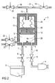
- a special feature of this embodiment is that the piston 12 on the control chamber 15 side facing is connected to two tension springs 26 which on the housing the powder feed pump 1 are attached.
- the two tension springs 26 assist the upward movement of the piston 12 during Aspirate the powder 2 in the working space 5 and take over the upward movement instead of the vacuum.
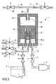
- FIG. 3 shows a further exemplary embodiment, also largely with the above-described and in the embodiment shown in FIG. 1, so that to avoid repetition largely to the above description is referenced to Figure 1 and for corresponding components the same reference numerals are used.
- a special feature of this embodiment is that the powder feed pump 1 two control rooms 15.1, 15.2 for pneumatic drive of the piston 12, wherein the Control chamber 15.1 on the side facing away from the working space 5 of the piston 12 is disposed while the control chamber 15.2 on the same side of the piston 12 as the working space 5th
- the control room 15.1 can be controlled in the same way be like the control room 15 in Figure 1, so that in this regard, reference is made to the above description becomes.
- control chamber 15.2 by a cup-shaped, cylindrical Wall 27 separated from the working space 5, wherein the working space 5 surrounds the control space 15. 2 annularly.
- the upward movement of the piston 12 is initiated here, by a connection 29 and a pressure relief valve 30th Compressed air is injected into the control chamber 15.2, whereby the piston 12 moves up while the powder. 2 via the powder inlet 6 in the working space 5 sucks.
- the advantage of this embodiment is the fact that the upward movement of the piston 12 for sucking the Powder 2 in the working space 5 with a considerably larger Force can be done as easily in the control room 15.2 create a strong overpressure, whereas the differential pressure when sucking the piston according to Figure 1 to a maximum 1 bar is limited.
Landscapes
- Reciprocating Pumps (AREA)
- Control Of The Air-Fuel Ratio Of Carburetors (AREA)
- Filling Or Emptying Of Bunkers, Hoppers, And Tanks (AREA)
- Air Transport Of Granular Materials (AREA)
- Coating Apparatus (AREA)
Abstract
Description
Die Erfindung betrifft eine Pulverförderpumpe, insbesondere
für eine Pulverbeschichtungseinrichtung, gemäß dem Oberbegriff
des Anspruchs 1.The invention relates to a powder feed pump, in particular
for a powder coating device, according to the preamble
of
Aus DE 101 45 448 A1 sowie aus WO 03/024613 A1 ist eine derartige Pulverförderpumpe bekannt, die in einer Beschichtungsmittelanlage eingesetzt werden kann, um das als Beschichtungsmittel dienende Pulver zu fördern. Diese bekannte Pulverförderpumpe weist einen mechanisch über eine Kolbenstange angetriebenen Hubkolben auf, der bei einer Aufwärtsbewegung ein Vakuum in einem Arbeitsraum der Pulverförderpumpe erzeugt, wodurch das Pulver über einen Pulvereinlass in den Arbeitsraum der Pulverförderpumpe eingesaugt wird. Anschließend wird dann Förderluft in den Arbeitsraum eingeblasen, wodurch das in dem Arbeitsraum befindliche Pulver über einen Pulverauslass ausgestoßen wird.From DE 101 45 448 A1 and from WO 03/024613 A1 is such Powder feed pump known in a coating plant can be used as a coating agent to promote serving powders. This known powder feed pump has a mechanical over a piston rod powered reciprocating piston, which in an upward movement generates a vacuum in a working space of the powder feed pump, causing the powder through a powder inlet into the working space the powder feed pump is sucked. Subsequently then conveying air is blown into the working space, whereby the powder in the working space via a powder outlet is ejected.
Nachteilig an dieser bekannten Pulverförderpumpe ist der aufwendige mechanische Antrieb, der über eine Kolbenstange durch Pneumatikzylinder erfolgt.A disadvantage of this known powder feed pump is the expensive mechanical drive, which passes through a piston rod Pneumatic cylinder takes place.
Der Erfindung liegt deshalb die Aufgabe zugrunde, bei der vorstehend beschriebenen bekannten Pulverförderpumpe den Antrieb zu vereinfachen.The invention is therefore based on the object, in the previously described known powder feed pump the drive to simplify.
Diese Aufgabe wird, ausgehend von der vorstehend beschriebenen
bekannten Pulverförderpumpe gemäß dem Oberbegriff des Anspruchs
1, durch die kennzeichnenden Merkmale des Anspruchs 1
gelöst. This object is based on the above-described
known powder feed pump according to the preamble of the
Die Erfindung umfasst die allgemeine technische Lehre, den Kolben pneumatisch direkt anzutreiben, so dass auf eine Kolbenstange zur mechanischen Verbindung des Kolbens mit der Antriebseinheit (z.B. Pneumatikzylinder) verzichtet werden kann. Ein weiterer Vorteil des erfindungsgemäßen Antriebs besteht darin, dass die Zahl und die Masse der bewegten Teile kleiner ist, wodurch die Verschleißanfälligkeit verringert und die Vibrationen gemindert werden.The invention comprises the general technical teaching, the Actuate piston pneumatically directly, so that on a piston rod for the mechanical connection of the piston to the drive unit (e.g., pneumatic cylinders) can. Another advantage of the drive according to the invention exists in that the number and mass of the moving parts is smaller, reducing the susceptibility to wear and the vibrations are reduced.
Vorzugsweise ist zum pneumatischen Antrieb des Kolbens ein Steuerraum vorgesehen, wobei der Kolben eine Begrenzungsfläche des Steuerraums bildet. Der Druck in dem Steuerraum ist hierbei einstellbar, um einen entsprechenden Druck auf den Kolben auszuüben und diesen entsprechend zu bewegen.Preferably, the pneumatic drive of the piston is a Control space provided, wherein the piston has a boundary surface of the control room forms. The pressure in the control room is adjustable to a corresponding pressure on the Exercise piston and move it accordingly.
In einem Ausführungsbeispiel der Erfindung sind der Steuerraum und der Arbeitsraum der Pulverförderpumpe hierbei auf gegenüberliegenden Seiten des Kolbens angeordnet, wobei der Kolben den Steuerraum von dem Arbeitsraum trennt. Eine Druckerhöhung in dem Steuerraum bewirkt hierbei also eine Abwärtsbewegung des Kolbens und eine entsprechende Verringerung des Arbeitsraumvolumens, wohingegen eine Druckverringerung in dem Steuerraum eine Aufwärtsbewegung des Kolbens bewirkt und zu einer entsprechenden Vergrößerung des Arbeitsraumvolumens führt.In one embodiment of the invention, the control room and the working space of the powder feed pump here on arranged opposite sides of the piston, wherein the Piston separates the control room from the working space. An increase in pressure in the control room in this case thus causes a downward movement of the piston and a corresponding reduction in the Workspace volume, whereas a pressure reduction in the Control chamber causes an upward movement of the piston and to a corresponding increase in the working space volume leads.
In einem anderen Ausführungsbeispiel der Erfindung sind der Steuerraum und der Arbeitsraum dagegen auf derselben Seite des Kolbens angeordnet, so dass der Steuerraum und der Arbeitsraum vorzugsweise auf dieselbe Stirnfläche des Kolbens wirken. Beispielsweise kann der Arbeitsraum den Steuerraum ringförmig umgeben, wobei der Steuerraum durch eine zylindrische Wandung von dem Arbeitsraum getrennt ist. Der Kolben weist hierbei also auf einer Seite zwei axial hervorstehende und koaxial angeordnete Teilkolben auf, zwischen denen eine ringförmige Nut verläuft, in die die zylindrische Wandung zwischen dem Arbeitsraum und dem Steuerraum eingreift. Die Anordnung des Arbeitsraumes an der Außenseite des Steuerraumes ist vorteilhaft, weil sich dadurch ein größeres Arbeitsraumvolumen ergibt, was zu einer entsprechend größeren Fördermenge führt. Es ist jedoch bei diesem Ausführungsbeispiel alternativ auch möglich, dass der Steuerraum den Arbeitsraum ringförmig umgibt.In another embodiment of the invention are the Control room and the work space on the other hand on the same page arranged the piston, so that the control room and the working space preferably on the same end face of the piston Act. For example, the working space may be the control room surrounded annular, wherein the control chamber by a cylindrical Wall is separated from the work space. The piston in this case has two axially projecting on one side and coaxially arranged part pistons, between which a annular groove extends, in which the cylindrical wall between the working space and the control room engages. The Arrangement of the working space on the outside of the control room is advantageous because it creates a larger workspace volume results, resulting in a correspondingly larger flow leads. However, it is in this embodiment alternatively also possible that the control room the work space surrounds annularly.
Darüber hinaus besteht bei diesem Ausführungsbeispiel die Möglichkeit, dass auf beiden Seiten des Kolbens jeweils ein Steuerraum angeordnet ist, um den Kolben pneumatisch direkt anzutreiben, wobei die beiden Steuerräume auf die gegenüberliegenden Stirnflächen des Kolbens wirken.Moreover, in this embodiment, the Possibility that on both sides of the piston one each Control chamber is arranged to pneumatically direct the piston to drive, with the two control rooms on the opposite Face surfaces of the piston act.
Zum pneumatischen Antrieb kann in den oder die Steuerräume ein Überdruckanschluss münden, um einen Überdruck in dem Steuerraum zu erzeugen und den Kolben entsprechend zu bewegen, wodurch das Arbeitsraumvolumen entsprechend verändert wird. Falls der Steuerraum auf der dem Arbeitsraum gegenüberliegenden Seite des Kolbens angeordnet ist, so führt eine Druckerhöhung in den Steuerraum zu einer Abwärtsbewegung des Kolbens und einer entsprechenden Verringerung des Arbeitsraumvolumens. Falls sich der Steuerraum dagegen auf derselben Seite befindet, wie der Arbeitsraum, so führt eine Druckerhöhung in dem Steuerraum durch den Überdruckanschluss zu einer Aufwärtsbewegung des Kolbens und einer entsprechenden Vergrößerung des Arbeitsraumvolumens.For pneumatic drive can be in the or the control rooms an overpressure port open to an overpressure in the Create control chamber and move the piston accordingly, whereby the work space volume changed accordingly becomes. If the control room on the opposite of the work space Side of the piston is arranged, so leads a Pressure increase in the control room to a downward movement of the Piston and a corresponding reduction in the working space volume. If the control room on the other hand on the same Side is located, as the working space, so performs an increase in pressure in the control room through the pressure connection to a Upward movement of the piston and a corresponding increase the workspace volume.
Darüber hinaus kann in den oder die Steuerräume ein Unterdruckanschluss münden, um den Druck in dem Steuerraum zu verringern, was zu einer entsprechenden Kolbenbewegung und einer Veränderung des Arbeitsraumvolumens führt. Bei einer Anordnung des Steuerraums auf der dem Arbeitsraum gegenüberliegenden Seite führt eine Verringerung des Drucks in dem Steuerraum zu einer Aufwärtsbewegung des Kolbens und einer entsprechenden Vergrößerung des Arbeitsraumvolumens. Bei einer Anordnung des Steuerraums auf derselben Seite wie der Arbeitsraum führt eine Druckverringerung in dem Steuerraum dagegen zu einer Abwärtsbewegung des Kolbens und einer entsprechenden Verringerung des Arbeitsraumvolumens.In addition, in the or the control rooms, a vacuum connection lead to reduce the pressure in the control room, resulting in a corresponding piston movement and a Change in the workspace volume leads. In an arrangement of the control room on the opposite of the work space Side leads to a reduction of the pressure in the control room to an upward movement of the piston and a corresponding Enlargement of the workspace volume. In an arrangement of the control room on the same side as the workroom leads a pressure reduction in the control room against it to a downward movement of the piston and a corresponding Reduction of the workspace volume.
Die pneumatische Steuerung des Kolbens kann im Rahmen der Erfindung ausschließlich durch eine Überdruckerzeugung auf den beiden Seiten des Kolbens erfolgen. Es ist jedoch alternativ auch möglich, das die pneumatische Steuerung des Kolbens ausschließlich durch eine Unterdruckerzeugung auf den gegenüberliegenden Seiten des Kolbens erfolgt. Darüber hinaus besteht auch die Möglichkeit einer Kombination einer Unterdruckerzeugung mit einer Überdruckerzeugung, wobei Unterdruck und Überdruck vorzugsweise auf derselben Seite des Kolbens erzeugt werden, um den Kolben entsprechend zu bewegen.The pneumatic control of the piston may be within the scope of the invention exclusively by overpressure generation on the done on both sides of the piston. It is however alternative also possible that the pneumatic control of the piston exclusively by a vacuum generation on the opposite Sides of the piston takes place. In addition there is also the possibility of a combination of a vacuum generation with overpressure generation, where negative pressure and overpressure preferably generated on the same side of the piston to move the piston accordingly.
In dem bevorzugten Ausführungsbeispiel der Erfindung dient die Kolbenbewegung nur zum Einsaugen des Pulvers in den Arbeitsraum, wohingegen das Ausstoßen des Pulvers aus dem Arbeitsraum durch den Pulverauslass nicht durch den Kolben erfolgt. Hierzu ist vorzugsweise ein Förderluftanschluss vorgesehen, der in den Arbeitsraum mündet, um Förderluft in den Arbeitsraum einzublasen und das in dem Arbeitsraum befindliche und zuvor eingesaugte Pulver durch den Pulverauslass auszustoßen.In the preferred embodiment of the invention is used the piston movement only for sucking the powder into the working space, whereas the ejection of the powder from the working space through the powder outlet not through the piston. For this purpose, a conveying air connection is preferably provided, which flows into the working space to conveying air in the Blowing work space and located in the work space and expel previously sucked powders through the powder outlet.
Vorzugsweise sind der Förderluftanschluss und der Pulverauslass in dem Arbeitsraum einander gegenüberliegend angeordnet. Dies bietet den Vorteil, dass der Strömungsverlauf vom Förderluftanschluss zum Pulverauslass das Ausstoßen des Pulvers unterstützt.Preferably, the conveying air connection and the powder outlet arranged in the working space opposite each other. This offers the advantage that the flow path from the conveying air connection to the powder outlet, the ejection of the powder supported.
Darüber hinaus kann in den Arbeitsraum auch ein Unterdruckanschluss münden, um den Kolben nach dem Ausstoßen des Pulvers aus dem Arbeitsraum zu bewegen und das Arbeitsraumvolumen entsprechend zu verändern. So muss der Kolben nach dem Ausstoßen des Pulvers zunächst wieder abwärts (d.h. in Richtung des Arbeitsraums) bewegt werden, um das Arbeitsraumvolumen zu verringern, damit anschließend erneut Pulver in den Arbeitsraum eingesaugt werden kann.In addition, in the working space can also be a vacuum connection lead to the piston after the expulsion of the powder to move out of the workroom and the workspace volume change accordingly. So the piston has to after ejecting initially back down (i.e., in the direction of of the working space) to increase the working space volume reduce, then again powder in the work space can be sucked.
Die Aufwärts- oder Abwärtsbewegung des Kolbens kann auch durch eine Feder unterstützt oder bewirkt werden, wobei die Feder den Kolben wahlweise drücken oder ziehen kann. Der Kolben kann also mit einer Druck- oder Zugfeder verbunden sein, die den Kolben in eine Ausgangsstellung bewegt, wenn kein äußerer pneumatischer Druck wirkt. Beispielsweise kann die Feder den Kolben zum Einsaugen des Pulvers nach oben (d.h. in Richtung des Steuerraums) bewegen, wohingegen die anschließende Abwärtsbewegung des Kolbens ausschließlich pneumatisch angetrieben wird.The upward or downward movement of the piston can also be supported or effected by a spring, wherein the Spring can either push or pull the piston. The piston can therefore be connected to a compression or tension spring, which moves the piston to an initial position, if no outer pneumatic pressure acts. For example, the spring the piston for sucking the powder upwards (i.e. Direction of the control room), whereas the subsequent one Downward movement of the piston exclusively pneumatically is driven.
Weiterhin ist es vorteilhaft, wenn in dem Arbeitsraum und/oder in dem Steuerraum mindestens ein Anschlag angeordnet ist, der die Kolbenbewegung begrenzt, um ein definiertes Hubvolumen zu erreichen und dadurch eine vorgegebene Fördermenge zu erzielen.Furthermore, it is advantageous if in the work space and / or arranged in the control room at least one stop is that limits the piston movement to a defined displacement to reach and thereby a predetermined flow rate to achieve.
Ferner ist es vorteilhaft, wenn der Kolben aus einem elastischen Material besteht, um eine möglichst gute Dichtwirkung zwischen dem Kolben und der umgebenden Lauffläche zu erreichen. Furthermore, it is advantageous if the piston of an elastic Material exists to ensure the best possible sealing effect between the piston and the surrounding tread.
Beispielsweise kann der Kolben aus einem Kunststoff bestehen, der sich elastisch an die Lauffläche anlegt. Dies ist auch vorteilhaft, weil Kunststoff relativ leicht ist, so dass im oszillierenden Betrieb des Kolbens geringere Massenkräfte auftreten, wodurch die Vibrationen herabgesetzt werden.For example, the piston may consist of a plastic, which applies elastically to the tread. This is also advantageous because plastic is relatively light, so in the oscillating operation of the piston lower mass forces occur, whereby the vibrations are reduced.
Ferner kann der Kolben an seiner Mantelfläche eine einstückig angeformte Dichtlippe aufweisen, um Pulverreste an der Lauffläche ohne einen separaten Kolbenring abzustreifen. Der Kolben kann also wie ein Molch aufgebaut sein, der in modernen Beschichtungsanlagen zur Reinigung von Farbleitungen eingesetzt wird.Furthermore, the piston on its lateral surface in one piece molded sealing lip to powder residues on the tread without stripping a separate piston ring. The piston So it can be built like a newt in modern times Coating systems used to clean paint lines becomes.
Ferner ist zu erwähnen, dass die Erfindung nicht auf die vorstehend beschriebene erfindungsgemäße Pulverförderpumpe als einzelnes Bauteil beschränkt ist, sondern auch eine vollständige Pulverbeschichtungsanlage mit einer derartigen Pulverförderpumpe umfasst.It should also be noted that the invention is not limited to the above described powder feed pump according to the invention single component is limited, but also a complete one Powder coating plant with such a powder feed pump includes.
Darüber hinaus umfasst die Erfindung auch die neuartige Verwendung einer derartigen Pulverförderpumpe zur Pulverförderung in einer Pulverbeschichtungsanlage.In addition, the invention also includes the novel use Such a powder feed pump for powder delivery in a powder coating plant.
Andere vorteilhafte Weiterbildungen der Erfindung sind in den Unteransprüchen gekennzeichnet oder werden nachstehend zusammen mit der Beschreibung der bevorzugten Ausführungsbeispiele der Erfindung anhand der Figuren näher erläutert. Es zeigen:
Figur 1- eine schematische Darstellung einer erfindungsgemäßen Pulverförderpumpe zur Förderung von Pulver in einer Pulverbeschichtungsanlage,
Figur 2- eine Abwandlung der Pulverförderpumpe aus
Figur 1 mit Federn zur Unterstützung der Kolbenbewegung sowie Figur 3- ein weiteres Ausführungsbeispiel einer erfindungsgemäßen Pulverförderpumpe.
- FIG. 1
- a schematic representation of a powder feed pump according to the invention for the promotion of powder in a powder coating plant,
- FIG. 2
- a modification of the powder feed pump of Figure 1 with springs to support the piston movement and
- FIG. 3
- a further embodiment of a powder feed pump according to the invention.
Die schematische Darstellung in Figur 1 zeigt eine Pulverförderpumpe
1, die in einer Pulverbeschichtungsanlage eingesetzt
werden kann, um ein als Beschichtungsmittel dienendes Pulver
2 aus einem Pulverbehälter 3 zu einem als Applikationsgerät
dienenden Rotationszerstäuber 4 zu fördern.The schematic representation in Figure 1 shows a
Der Pulverbehälter 3 und der Rotationszerstäuber 4 können
hierbei herkömmlich ausgebildet sein, so dass im Folgenden
auf eine detaillierte Beschreibung des Pulverbehälters 3 und
des Rotationszerstäubers 4 verzichtet werden kann und diesbezüglich
auf die einschlägige Fachliteratur verwiesen wird.The
Weiterhin kann anstelle des Rotationszerstäubers 4 auch ein
anderes Applikationsgerät verwendet werden, wie beispielsweise
eine Pulversprühpistole.Furthermore, instead of the
Ferner können zwischen dem Pulverbehälter 3 und der Pulverförderpumpe
1 sowie zwischen der Pulverförderpumpe 1 und dem
Rotationszerstäuber 4 weitere Bauteile und Komponenten angeordnet
sein, die jedoch hier zur Vereinfachung nicht dargestellt
sind.Further, between the
Die Pulverförderpumpe 1 weist einen Arbeitsraum 5 mit einem
veränderlichen Arbeitsraumvolumen auf, wobei in den Arbeitsraum
5 ein Pulvereinlass 6 mündet, der über eine Zuleitung 7
und ein Pulvereinlassventil 8 mit dem Pulverbehälter 3 verbunden
ist. Bei geöffnetem Pulvereinlassventil 8 kann das
Pulver 2 also über die Zuleitung 7 und den Pulvereinlass 6 in
den Arbeitsraum 5 der Pulverförderpumpe 1 eingesaugt werden.The
Weiterhin mündet ein Pulverauslass 9 in den Arbeitsraum 5 der
Pulverförderpumpe 1, wobei der Pulverauslass 9 über eine Austragsleitung
10 und ein Pulverauslassventil 11 mit dem Rotationszerstäuber
4 verbunden ist. Bei geöffnetem Pulverauslassventil
11 kann also das in den Arbeitsraum 5 der Pulverförderpumpe
1 eingesaugte Pulver 2 über den Pulverauslass 9
ausgestoßen und zu dem Rotationszerstäuber 4 gefördert werden.Furthermore, a
Das Arbeitsraumvolumen des Arbeitsraums 5 ist durch einen
Kolben 12 veränderbar, der in Pfeilrichtung verschiebbar in
der Pulverförderpumpe 1 angeordnet ist.The working space volume of the working
Der Kolben 12 besteht aus einem elastischen Kunststoff und
weist an seiner Mantelfläche 2 axial beabstandete Dichtlippen
13 auf, die Pulverreste von einer zugehörigen Lauffläche 14
abstreifen.The
Weiterhin weist die Pulverförderpumpe 1 einen Steuerraum 15
auf, der auf der dem Arbeitsraum 5 gegenüberliegenden Seite
des Kolbens 12 angeordnet ist. In den Steuerraum 15 mündet
ein Anschluss 16, der über eine Überdruckleitung 17 und ein
Überdruckventil 18 mit einer Überdruckquelle verbunden ist.Furthermore, the
Weiterhin ist der Anschluss 16 über eine Unterdruckleitung 19
und ein Unterdruckventil 20 mit einer Unterdruckquelle verbunden,
die ebenso wie die Überdruckquelle zur Vereinfachung
nicht dargestellt ist. Über den Anschluss 16 kann der Druck
in dem Steuerraum 15 eingestellt werden, um die Bewegung des
Kolbens 12 zu steuern. Zur Abwärtsbewegung des Kolbens 12
wird das Überdruckventil 18 geöffnet, während das Unterdruckventil
20 geschlossen wird, wodurch der Druck in dem Steuerraum
15 entsprechend ansteigt und sich der Kolben 12 nach unten
bewegt.Furthermore, the
Weiterhin mündet in den Arbeitsraum 5 der Pulverförderpumpe 1
ein Anschluss 21, der über ein Förderluftventil 22 mit einer
Förderluftquelle verbunden. Im geöffneten Zustand des Förderluftventils
22 wird über den Anschluss 21 Förderluft in den
Arbeitsraum 5 der Pulverförderpumpe 1 eingeblasen, wodurch
das in dem Arbeitsraum 5 befindliche Pulver 2 über den Pulverauslass
9 ausgestoßen wird, falls das Pulverauslassventil 11
geöffnet ist.Furthermore, opens into the working
Zusätzlich kann an den Anschluss 21 über ein Unterdruckventil
23 ein Unterdruckanschluss angeschlossen sein, um einen
Unterdruck in dem Arbeitsraum 5 zu erzeugen und den Kolben 12
dadurch nach unten zu ziehen. Diese Unterdrucksteuerung des
Kolbens 12 ist jedoch nur optional und wird deshalb nicht
weiter beschrieben.In addition, it can be connected to port 21 via a vacuum valve
23 a vacuum connection to be connected to a
To generate negative pressure in the working
Schließlich weist die Pulverförderpumpe 1 einen in den Steuerraum
15 hineinragenden Anschlag 24 und einen in den Arbeitsraum
5 hineinragenden Anschlag 25 auf, wobei die beiden
Anschläge 24, 25 die Kolbenbewegung begrenzen und dadurch ein
definiertes maximales Hubvolumen einstellen.Finally, the
Im Folgenden wird nun ein vollständiger Arbeitstakt der Pulverförderpumpe
1 beschrieben, wobei sich der Kolben 12 zu Beginn
des beschriebenen Arbeitstaktes an dem unteren Anschlag
25 befindet, während das Pulvereinlassventil 8, das Pulverauslassventil
11, das Förderluftventil 22, das Unterdruckventil
20 und das Überdruckventil 18 geschlossen sind. The following is now a complete stroke of the
Zu Beginn des Arbeitstaktes werden dann das Pulvereinlassventil
8 und das Unterdruckventil 20 geöffnet, wodurch Luft aus
dem Steuerraum 15 abgesaugt wird, was zu einer entsprechenden
Druckminderung in dem Steuerraum 15 und einer Aufwärtsbewegung
des Kolbens 12 führt. Die Aufwärtsbewegung des Kolbens
12 führt wiederum zu einer Druckminderung in dem Arbeitsraum
5, wodurch das Pulver 2 aus dem Pulverbehälter 3 über den
Pulvereinlass 6 in den Arbeitsraum 5 eingesaugt wird.At the beginning of the power stroke then the
Wenn der Kolben 12 an dem oberen Anschlag 24 anstößt, werden
das Pulvereinlassventil 8 und das Unterdruckventil 20 geschlossen,
während das Pulverauslassventil 11 und das Förderluftventil
22 geöffnet werden. Dadurch wird Förderluft über
den Anschluss 21 in den Arbeitsraum 5 geblasen, wodurch das
in dem Arbeitsraum 5 befindliche Pulver über den Pulverauslass
9 ausgestoßen wird.When the
Nach dem Ausstoßen des Pulvers 2 aus dem Arbeitsraum 5 wird
dann bei weiterhin geöffnetem Pulverauslassventil 11 das Förderluftventil
22 geschlossen, während das Überdruckventil 18
geöffnet werden. Dadurch bewegt sich der Kolben 12 nach unten,
bis der Kolben 12 schließlich an dem Anschlag 25 anstößt,
woraufhin das Überdruckventil 18 geschlossen wird, so
dass der Arbeitstakt beendet ist.After ejecting the
Das in Figur 2 dargestellte Ausführungsbeispiel stimmt weitgehend mit dem vorstehend beschriebenen und in Figur 1 dargestellten Ausführungsbeispiel überein, so dass zur Vermeidung von Wiederholungen weitgehend auf die vorstehende Beschreibung verwiesen wird und für entsprechende Bauteile dieselben Bezugszeichen verwendet werden.The embodiment shown in Figure 2 is largely true with the one described above and shown in FIG Embodiment match, so that to avoid from repetitions largely to the above description is referenced and the same for corresponding components Reference numerals are used.
Eine Besonderheit dieses Ausführungsbeispiels besteht darin,
dass der Kolben 12 auf der dem Steuerraum 15 zugewandten Seite
mit zwei Zugfedern 26 verbunden ist, die an dem Gehäuse
der Pulverförderpumpe 1 befestigt sind. Die beiden Zugfedern
26 unterstützen die Aufwärtsbewegung des Kolbens 12 beim
Einsaugen des Pulvers 2 in den Arbeitsraum 5 und übernehmen
die Aufwärtsbewegung anstelle des Vakuums.A special feature of this embodiment is
that the
Schließlich zeigt Figur 3 ein weiteres Ausführungsbeispiel, das ebenfalls weitgehend mit dem vorstehend beschriebenen und in Figur 1 dargestellten Ausführungsbeispiel übereinstimmt, so dass zur Vermeidung von Wiederholungen weitgehend auf die vorstehende Beschreibung zu Figur 1 verwiesen wird und für entsprechende Bauteile dieselben Bezugszeichen verwendet werden.Finally, FIG. 3 shows a further exemplary embodiment, also largely with the above-described and in the embodiment shown in FIG. 1, so that to avoid repetition largely to the above description is referenced to Figure 1 and for corresponding components the same reference numerals are used.
Eine Besonderheit dieses Ausführungsbeispiels besteht darin,
dass die Pulverförderpumpe 1 zwei Steuerräume 15.1, 15.2 zum
pneumatischen Antrieb des Kolbens 12 aufweist, wobei der
Steuerraum 15.1 auf der dem Arbeitsraum 5 abgewandten Seite
des Kolbens 12 angeordnet ist, während sich der Steuerraum
15.2 auf derselben Seite des Kolbens 12 befindet wie der Arbeitsraum
5.A special feature of this embodiment is
that the
Der Steuerraum 15.1 kann hierbei in der gleichen Weise angesteuert
werden, wie der Steuerraum 15 in Figur 1, so dass
diesbezüglich auf die vorstehende Beschreibung verwiesen
wird.The control room 15.1 can be controlled in the same way
be like the
Der Steuerraum 15.2 ist dagegen durch eine topfförmige, zylindrische
Wandung 27 von dem Arbeitsraum 5 getrennt, wobei
der Arbeitsraum 5 den Steuerraum 15.2 ringförmig umgibt.The control chamber 15.2, however, by a cup-shaped, cylindrical
Wall 27 separated from the working
Weiterhin befindet sich in dem Kolben 12 eine ringförmige Nut
28, in die die Wandung 27 eingreift. Furthermore, there is an annular groove in the
Die Aufwärtsbewegung des Kolbens 12 wird hierbei eingeleitet,
indem über einen Anschluss 29 und ein Überdruckventil 30
Druckluft in den Steuerraum 15.2 eingeblasen wird, wodurch
sich der Kolben 12 nach oben bewegt und dabei das Pulver 2
über den Pulvereinlass 6 in den Arbeitsraum 5 einsaugt.The upward movement of the
Bei der Abwärtsbewegung des Kolbens 12 wird der Überdruckanschluss
30 dagegen geschlossen, wohingegen ein mit dem Anschluss
29 verbundenes Auslassventil 31 geöffnet wird, so
dass die in dem Steuerraum 15.2 befindliche Luft bei einer
Abwärtsbewegung des Kolbens 12 über das Auslassventil 31 in
die Umgebung abgegeben werden kann.During the downward movement of the
Vorteilhaft an diesem Ausführungsbeispiel ist die Tatsache,
dass die Aufwärtsbewegung des Kolbens 12 zum Einsaugen des
Pulvers 2 in den Arbeitsraum 5 mit einer erheblich größeren
Kraft erfolgen kann, da sich in dem Steuerraum 15.2 leicht
ein starker Überdruck erzeugen lässt, wohingegen der Differenzdruck
beim Ansaugen des Kolbens gemäß Figur 1 auf maximal
1 Bar begrenzt ist.The advantage of this embodiment is the fact
that the upward movement of the
Die Erfindung ist nicht auf die vorstehend beschriebenen Ausführungsbeispiele beschränkt. Vielmehr ist eine Vielzahl von Varianten und Abwandlungen möglich, die ebenfalls von dem Erfindungsgedanken Gebrauch machen und deshalb in den Schutzbereich fallen.The invention is not limited to the embodiments described above limited. Rather, a variety of Variants and modifications possible, which also from the inventive idea Use and therefore in the scope of protection fall.
Claims (20)
der Kolben (12) pneumatisch direkt angetrieben ist.Powder feed pump (1), in particular for a powder coating device, with
the piston (12) is pneumatically driven directly.
einen Steuerraum (15, 15.1, 15.2) zum pneumatischen Antrieb des Kolbens (12), wobei der Kolben (12) eine Begrenzungsfläche des Steuerraums (15, 15.1, 15.2) bildet.Powder feed pump (1) according to claim 1, characterized by
a control chamber (15, 15.1, 15.2) for the pneumatic drive of the piston (12), wherein the piston (12) forms a boundary surface of the control chamber (15, 15.1, 15.2).
Applications Claiming Priority (2)
| Application Number | Priority Date | Filing Date | Title |
|---|---|---|---|
| DE102004011445 | 2004-03-09 | ||
| DE102004011445A DE102004011445A1 (en) | 2004-03-09 | 2004-03-09 | Powder feed pump |
Publications (3)
| Publication Number | Publication Date |
|---|---|
| EP1574261A2 true EP1574261A2 (en) | 2005-09-14 |
| EP1574261A3 EP1574261A3 (en) | 2007-09-26 |
| EP1574261B1 EP1574261B1 (en) | 2009-04-29 |
Family
ID=34813624
Family Applications (1)
| Application Number | Title | Priority Date | Filing Date |
|---|---|---|---|
| EP05004575A Expired - Lifetime EP1574261B1 (en) | 2004-03-09 | 2005-03-02 | Powder pump |
Country Status (4)
| Country | Link |
|---|---|
| EP (1) | EP1574261B1 (en) |
| AT (1) | ATE429978T1 (en) |
| DE (2) | DE102004011445A1 (en) |
| ES (1) | ES2325770T3 (en) |
Cited By (1)
| Publication number | Priority date | Publication date | Assignee | Title |
|---|---|---|---|---|
| EP1772195A3 (en) * | 2005-10-07 | 2008-09-17 | Nordson Corporation | Pump with suction and pressure control for dry particulate material |
Families Citing this family (1)
| Publication number | Priority date | Publication date | Assignee | Title |
|---|---|---|---|---|
| DE102007011736A1 (en) * | 2007-03-10 | 2008-09-11 | Bayerische Motoren Werke Aktiengesellschaft | Conveying device for conveying powder, particularly powder coating, out of storage container into powder discharge unit, has closed housing, and air permeable fluid base is arranged in housing that is spaced from front side of housing |
Citations (1)
| Publication number | Priority date | Publication date | Assignee | Title |
|---|---|---|---|---|
| WO2003024613A1 (en) | 2001-09-14 | 2003-03-27 | Bayerische Motoren Werke Aktiengesellschaft | Device for conveying powder and method for operation thereof |
Family Cites Families (3)
| Publication number | Priority date | Publication date | Assignee | Title |
|---|---|---|---|---|
| CH652100A5 (en) * | 1983-04-28 | 1985-10-31 | Frederic Dietrich | POWDER TRANSPORT PROCESS AND IMPLEMENTATION DEVICE. |
| US5203507A (en) * | 1990-12-11 | 1993-04-20 | Matthews Richard H | Air powered sprayer for dispensing material slurries |
| DE19959473A1 (en) * | 1999-12-10 | 2001-06-13 | Frederic Dietrich | Device and method for the pneumatic conveying of powdery substances and use of the device |
-
2004
- 2004-03-09 DE DE102004011445A patent/DE102004011445A1/en not_active Withdrawn
-
2005
- 2005-03-02 AT AT05004575T patent/ATE429978T1/en not_active IP Right Cessation
- 2005-03-02 EP EP05004575A patent/EP1574261B1/en not_active Expired - Lifetime
- 2005-03-02 ES ES05004575T patent/ES2325770T3/en not_active Expired - Lifetime
- 2005-03-02 DE DE502005007168T patent/DE502005007168D1/en not_active Expired - Lifetime
Patent Citations (2)
| Publication number | Priority date | Publication date | Assignee | Title |
|---|---|---|---|---|
| WO2003024613A1 (en) | 2001-09-14 | 2003-03-27 | Bayerische Motoren Werke Aktiengesellschaft | Device for conveying powder and method for operation thereof |
| DE10145448A1 (en) | 2001-09-14 | 2003-05-22 | Bayerische Motoren Werke Ag | Device for conveying powder and method for operating it |
Cited By (4)
| Publication number | Priority date | Publication date | Assignee | Title |
|---|---|---|---|---|
| EP1772195A3 (en) * | 2005-10-07 | 2008-09-17 | Nordson Corporation | Pump with suction and pressure control for dry particulate material |
| US7731456B2 (en) | 2005-10-07 | 2010-06-08 | Nordson Corporation | Dense phase pump with open loop control |
| US8167517B2 (en) | 2005-10-07 | 2012-05-01 | Nordson Corporation | Pump with suction and pressure control for dry particulate material |
| US8491227B2 (en) | 2005-10-07 | 2013-07-23 | Nordson Corporation | Pump for powder coating materials with data structure for storing powder flow recipes |
Also Published As
| Publication number | Publication date |
|---|---|
| EP1574261B1 (en) | 2009-04-29 |
| DE102004011445A1 (en) | 2005-09-22 |
| ATE429978T1 (en) | 2009-05-15 |
| ES2325770T3 (en) | 2009-09-16 |
| DE502005007168D1 (en) | 2009-06-10 |
| EP1574261A3 (en) | 2007-09-26 |
Similar Documents
| Publication | Publication Date | Title |
|---|---|---|
| EP0309010B1 (en) | Manual fluid dispenser | |
| DE2227407C3 (en) | Hand pump for pumping filling material from a container | |
| DE4102506C2 (en) | Discharge device for media | |
| DE602004008632T3 (en) | PROCEDURE FOR CONVEYING POWDER MATERIAL THROUGH PIPING | |
| AT393486B (en) | DOUBLE ACTING MECHANICAL PUMP FOR SPRAYER OF LIQUIDS | |
| EP1437178A2 (en) | Powder pumping installation, Method therefore and powder coating installation | |
| DE2818507A1 (en) | MANUAL AXIAL PISTON PUMP | |
| DE10145448A1 (en) | Device for conveying powder and method for operating it | |
| DE3741185A1 (en) | CONTROL DEVICE FOR AIR-POWERED TOOLS | |
| EP0744250A2 (en) | Fastener driving tool | |
| DE102011082420A1 (en) | liquid dispenser | |
| WO2023041655A1 (en) | Spray gun, and method for operating a spray gun | |
| DE69624642T2 (en) | pump mechanism | |
| EP2956242B1 (en) | Coating agent pump and cleaning method for a coating agent pump | |
| EP0451615B1 (en) | Discharge device for at least one medium | |
| DE2452878B2 (en) | Spray pump for liquid contained in a container | |
| EP1574261B1 (en) | Powder pump | |
| DE2339933A1 (en) | DEVICE FOR SPRAY LUBRICATION OF SINTER FORMS | |
| DE4302951C1 (en) | Ejector pump diffuser obturator - has compressed-gas passage to diffuser shut by plug when in rest position | |
| EP1468745B1 (en) | Spray element for a sprayer head | |
| DE112018004607B4 (en) | Fluid delivery mechanism and spray device for a fluid | |
| EP3519024B1 (en) | Atomiser, in particular inhaler, for atomising a liquid active agent to form an aerosol and a corresponding method | |
| DE102004011444A1 (en) | Powder pump, for a powder coating spray jet, has a moving membrane at its working zone to expand and contract the zone to draw in powder and force it out to the jet | |
| DE2711208A1 (en) | Viscous material metering equipment - generates vacuum in dispensing chamber to compress material before driving out | |
| DE60009128T2 (en) | PUMP WITH FAST FLOATING |
Legal Events
| Date | Code | Title | Description |
|---|---|---|---|
| PUAI | Public reference made under article 153(3) epc to a published international application that has entered the european phase |
Free format text: ORIGINAL CODE: 0009012 |
|
| AK | Designated contracting states |
Kind code of ref document: A2 Designated state(s): AT BE BG CH CY CZ DE DK EE ES FI FR GB GR HU IE IS IT LI LT LU MC NL PL PT RO SE SI SK TR |
|
| AX | Request for extension of the european patent |
Extension state: AL BA HR LV MK YU |
|
| PUAL | Search report despatched |
Free format text: ORIGINAL CODE: 0009013 |
|
| AK | Designated contracting states |
Kind code of ref document: A3 Designated state(s): AT BE BG CH CY CZ DE DK EE ES FI FR GB GR HU IE IS IT LI LT LU MC NL PL PT RO SE SI SK TR |
|
| AX | Request for extension of the european patent |
Extension state: AL BA HR LV MK YU |
|
| 17P | Request for examination filed |
Effective date: 20080310 |
|
| AKX | Designation fees paid |
Designated state(s): AT BE BG CH CY CZ DE DK EE ES FI FR GB GR HU IE IS IT LI LT LU MC NL PL PT RO SE SI SK TR |
|
| GRAP | Despatch of communication of intention to grant a patent |
Free format text: ORIGINAL CODE: EPIDOSNIGR1 |
|
| GRAP | Despatch of communication of intention to grant a patent |
Free format text: ORIGINAL CODE: EPIDOSNIGR1 |
|
| GRAS | Grant fee paid |
Free format text: ORIGINAL CODE: EPIDOSNIGR3 |
|
| GRAA | (expected) grant |
Free format text: ORIGINAL CODE: 0009210 |
|
| AK | Designated contracting states |
Kind code of ref document: B1 Designated state(s): AT BE BG CH CY CZ DE DK EE ES FI FR GB GR HU IE IS IT LI LT LU MC NL PL PT RO SE SI SK TR |
|
| REG | Reference to a national code |
Ref country code: GB Ref legal event code: FG4D Free format text: NOT ENGLISH |
|
| REG | Reference to a national code |
Ref country code: CH Ref legal event code: EP |
|
| REF | Corresponds to: |
Ref document number: 502005007168 Country of ref document: DE Date of ref document: 20090610 Kind code of ref document: P |
|
| REG | Reference to a national code |
Ref country code: DE Ref legal event code: R096 Ref document number: 502005007168 Country of ref document: DE Effective date: 20090610 Ref country code: IE Ref legal event code: FG4D |
|
| REG | Reference to a national code |
Ref country code: SE Ref legal event code: TRGR |
|
| REG | Reference to a national code |
Ref country code: ES Ref legal event code: FG2A Ref document number: 2325770 Country of ref document: ES Kind code of ref document: T3 |
|
| PG25 | Lapsed in a contracting state [announced via postgrant information from national office to epo] |
Ref country code: LT Free format text: LAPSE BECAUSE OF FAILURE TO SUBMIT A TRANSLATION OF THE DESCRIPTION OR TO PAY THE FEE WITHIN THE PRESCRIBED TIME-LIMIT Effective date: 20090429 Ref country code: FI Free format text: LAPSE BECAUSE OF FAILURE TO SUBMIT A TRANSLATION OF THE DESCRIPTION OR TO PAY THE FEE WITHIN THE PRESCRIBED TIME-LIMIT Effective date: 20090429 Ref country code: PT Free format text: LAPSE BECAUSE OF FAILURE TO SUBMIT A TRANSLATION OF THE DESCRIPTION OR TO PAY THE FEE WITHIN THE PRESCRIBED TIME-LIMIT Effective date: 20090829 |
|
| PG25 | Lapsed in a contracting state [announced via postgrant information from national office to epo] |
Ref country code: SI Free format text: LAPSE BECAUSE OF FAILURE TO SUBMIT A TRANSLATION OF THE DESCRIPTION OR TO PAY THE FEE WITHIN THE PRESCRIBED TIME-LIMIT Effective date: 20090429 Ref country code: PL Free format text: LAPSE BECAUSE OF FAILURE TO SUBMIT A TRANSLATION OF THE DESCRIPTION OR TO PAY THE FEE WITHIN THE PRESCRIBED TIME-LIMIT Effective date: 20090429 Ref country code: IS Free format text: LAPSE BECAUSE OF FAILURE TO SUBMIT A TRANSLATION OF THE DESCRIPTION OR TO PAY THE FEE WITHIN THE PRESCRIBED TIME-LIMIT Effective date: 20090829 |
|
| REG | Reference to a national code |
Ref country code: IE Ref legal event code: FD4D |
|
| RAP2 | Party data changed (patent owner data changed or rights of a patent transferred) |
Owner name: DUERR SYSTEMS GMBH |
|
| PG25 | Lapsed in a contracting state [announced via postgrant information from national office to epo] |
Ref country code: DK Free format text: LAPSE BECAUSE OF FAILURE TO SUBMIT A TRANSLATION OF THE DESCRIPTION OR TO PAY THE FEE WITHIN THE PRESCRIBED TIME-LIMIT Effective date: 20090429 Ref country code: IE Free format text: LAPSE BECAUSE OF FAILURE TO SUBMIT A TRANSLATION OF THE DESCRIPTION OR TO PAY THE FEE WITHIN THE PRESCRIBED TIME-LIMIT Effective date: 20090429 Ref country code: CZ Free format text: LAPSE BECAUSE OF FAILURE TO SUBMIT A TRANSLATION OF THE DESCRIPTION OR TO PAY THE FEE WITHIN THE PRESCRIBED TIME-LIMIT Effective date: 20090429 Ref country code: RO Free format text: LAPSE BECAUSE OF FAILURE TO SUBMIT A TRANSLATION OF THE DESCRIPTION OR TO PAY THE FEE WITHIN THE PRESCRIBED TIME-LIMIT Effective date: 20090429 Ref country code: EE Free format text: LAPSE BECAUSE OF FAILURE TO SUBMIT A TRANSLATION OF THE DESCRIPTION OR TO PAY THE FEE WITHIN THE PRESCRIBED TIME-LIMIT Effective date: 20090429 |
|
| PG25 | Lapsed in a contracting state [announced via postgrant information from national office to epo] |
Ref country code: SK Free format text: LAPSE BECAUSE OF FAILURE TO SUBMIT A TRANSLATION OF THE DESCRIPTION OR TO PAY THE FEE WITHIN THE PRESCRIBED TIME-LIMIT Effective date: 20090429 |
|
| NLT2 | Nl: modifications (of names), taken from the european patent patent bulletin |
Owner name: DUERR SYSTEMS GMBH Effective date: 20100120 |
|
| PLBE | No opposition filed within time limit |
Free format text: ORIGINAL CODE: 0009261 |
|
| STAA | Information on the status of an ep patent application or granted ep patent |
Free format text: STATUS: NO OPPOSITION FILED WITHIN TIME LIMIT |
|
| REG | Reference to a national code |
Ref country code: DE Ref legal event code: R081 Ref document number: 502005007168 Country of ref document: DE Owner name: DUERR SYSTEMS AG, DE Free format text: FORMER OWNER: DUERR SYSTEMS GMBH, 70435 STUTTGART, DE Effective date: 20100115 |
|
| PG25 | Lapsed in a contracting state [announced via postgrant information from national office to epo] |
Ref country code: BG Free format text: LAPSE BECAUSE OF FAILURE TO SUBMIT A TRANSLATION OF THE DESCRIPTION OR TO PAY THE FEE WITHIN THE PRESCRIBED TIME-LIMIT Effective date: 20090729 |
|
| 26N | No opposition filed |
Effective date: 20100201 |
|
| REG | Reference to a national code |
Ref country code: DE Ref legal event code: R097 Ref document number: 502005007168 Country of ref document: DE Effective date: 20100201 |
|
| PG25 | Lapsed in a contracting state [announced via postgrant information from national office to epo] |
Ref country code: MC Free format text: LAPSE BECAUSE OF NON-PAYMENT OF DUE FEES Effective date: 20100331 Ref country code: GR Free format text: LAPSE BECAUSE OF FAILURE TO SUBMIT A TRANSLATION OF THE DESCRIPTION OR TO PAY THE FEE WITHIN THE PRESCRIBED TIME-LIMIT Effective date: 20090730 |
|
| REG | Reference to a national code |
Ref country code: CH Ref legal event code: PL |
|
| PG25 | Lapsed in a contracting state [announced via postgrant information from national office to epo] |
Ref country code: CH Free format text: LAPSE BECAUSE OF NON-PAYMENT OF DUE FEES Effective date: 20100331 Ref country code: LI Free format text: LAPSE BECAUSE OF NON-PAYMENT OF DUE FEES Effective date: 20100331 |
|
| PG25 | Lapsed in a contracting state [announced via postgrant information from national office to epo] |
Ref country code: AT Free format text: LAPSE BECAUSE OF NON-PAYMENT OF DUE FEES Effective date: 20100302 |
|
| PG25 | Lapsed in a contracting state [announced via postgrant information from national office to epo] |
Ref country code: CY Free format text: LAPSE BECAUSE OF FAILURE TO SUBMIT A TRANSLATION OF THE DESCRIPTION OR TO PAY THE FEE WITHIN THE PRESCRIBED TIME-LIMIT Effective date: 20090429 |
|
| PG25 | Lapsed in a contracting state [announced via postgrant information from national office to epo] |
Ref country code: LU Free format text: LAPSE BECAUSE OF NON-PAYMENT OF DUE FEES Effective date: 20100302 Ref country code: HU Free format text: LAPSE BECAUSE OF FAILURE TO SUBMIT A TRANSLATION OF THE DESCRIPTION OR TO PAY THE FEE WITHIN THE PRESCRIBED TIME-LIMIT Effective date: 20091030 |
|
| PG25 | Lapsed in a contracting state [announced via postgrant information from national office to epo] |
Ref country code: TR Free format text: LAPSE BECAUSE OF FAILURE TO SUBMIT A TRANSLATION OF THE DESCRIPTION OR TO PAY THE FEE WITHIN THE PRESCRIBED TIME-LIMIT Effective date: 20090429 |
|
| REG | Reference to a national code |
Ref country code: FR Ref legal event code: PLFP Year of fee payment: 11 |
|
| PGFP | Annual fee paid to national office [announced via postgrant information from national office to epo] |
Ref country code: DE Payment date: 20150320 Year of fee payment: 11 Ref country code: IT Payment date: 20150324 Year of fee payment: 11 Ref country code: NL Payment date: 20150319 Year of fee payment: 11 Ref country code: ES Payment date: 20150317 Year of fee payment: 11 |
|
| PGFP | Annual fee paid to national office [announced via postgrant information from national office to epo] |
Ref country code: GB Payment date: 20150319 Year of fee payment: 11 Ref country code: SE Payment date: 20150319 Year of fee payment: 11 Ref country code: FR Payment date: 20150319 Year of fee payment: 11 |
|
| PGFP | Annual fee paid to national office [announced via postgrant information from national office to epo] |
Ref country code: BE Payment date: 20150319 Year of fee payment: 11 |
|
| PG25 | Lapsed in a contracting state [announced via postgrant information from national office to epo] |
Ref country code: BE Free format text: LAPSE BECAUSE OF NON-PAYMENT OF DUE FEES Effective date: 20160331 |
|
| REG | Reference to a national code |
Ref country code: DE Ref legal event code: R082 Ref document number: 502005007168 Country of ref document: DE Representative=s name: V. BEZOLD & PARTNER PATENTANWAELTE - PARTG MBB, DE Ref country code: DE Ref legal event code: R081 Ref document number: 502005007168 Country of ref document: DE Owner name: DUERR SYSTEMS AG, DE Free format text: FORMER OWNER: DUERR SYSTEMS GMBH, 74321 BIETIGHEIM-BISSINGEN, DE |
|
| REG | Reference to a national code |
Ref country code: DE Ref legal event code: R119 Ref document number: 502005007168 Country of ref document: DE |
|
| REG | Reference to a national code |
Ref country code: SE Ref legal event code: EUG |
|
| REG | Reference to a national code |
Ref country code: NL Ref legal event code: MM Effective date: 20160401 |
|
| GBPC | Gb: european patent ceased through non-payment of renewal fee |
Effective date: 20160302 |
|
| PG25 | Lapsed in a contracting state [announced via postgrant information from national office to epo] |
Ref country code: SE Free format text: LAPSE BECAUSE OF NON-PAYMENT OF DUE FEES Effective date: 20160303 |
|
| REG | Reference to a national code |
Ref country code: FR Ref legal event code: ST Effective date: 20161130 |
|
| PG25 | Lapsed in a contracting state [announced via postgrant information from national office to epo] |
Ref country code: FR Free format text: LAPSE BECAUSE OF NON-PAYMENT OF DUE FEES Effective date: 20160331 Ref country code: GB Free format text: LAPSE BECAUSE OF NON-PAYMENT OF DUE FEES Effective date: 20160302 Ref country code: DE Free format text: LAPSE BECAUSE OF NON-PAYMENT OF DUE FEES Effective date: 20161001 Ref country code: NL Free format text: LAPSE BECAUSE OF NON-PAYMENT OF DUE FEES Effective date: 20160401 |
|
| PG25 | Lapsed in a contracting state [announced via postgrant information from national office to epo] |
Ref country code: IT Free format text: LAPSE BECAUSE OF NON-PAYMENT OF DUE FEES Effective date: 20160302 |
|
| REG | Reference to a national code |
Ref country code: ES Ref legal event code: FD2A Effective date: 20170428 |
|
| PG25 | Lapsed in a contracting state [announced via postgrant information from national office to epo] |
Ref country code: ES Free format text: LAPSE BECAUSE OF NON-PAYMENT OF DUE FEES Effective date: 20160303 |
|
| P01 | Opt-out of the competence of the unified patent court (upc) registered |
Effective date: 20230512 |