EP1574186B1 - Dispositif d'insertion navigué pour implants orthopédiques à tiges - Google Patents
Dispositif d'insertion navigué pour implants orthopédiques à tiges Download PDFInfo
- Publication number
- EP1574186B1 EP1574186B1 EP05251376A EP05251376A EP1574186B1 EP 1574186 B1 EP1574186 B1 EP 1574186B1 EP 05251376 A EP05251376 A EP 05251376A EP 05251376 A EP05251376 A EP 05251376A EP 1574186 B1 EP1574186 B1 EP 1574186B1
- Authority
- EP
- European Patent Office
- Prior art keywords
- stemmed
- implant
- inserter
- navigated
- stem
- Prior art date
- Legal status (The legal status is an assumption and is not a legal conclusion. Google has not performed a legal analysis and makes no representation as to the accuracy of the status listed.)
- Not-in-force
Links
Images


Classifications
-
- A—HUMAN NECESSITIES
- A61—MEDICAL OR VETERINARY SCIENCE; HYGIENE
- A61F—FILTERS IMPLANTABLE INTO BLOOD VESSELS; PROSTHESES; DEVICES PROVIDING PATENCY TO, OR PREVENTING COLLAPSING OF, TUBULAR STRUCTURES OF THE BODY, e.g. STENTS; ORTHOPAEDIC, NURSING OR CONTRACEPTIVE DEVICES; FOMENTATION; TREATMENT OR PROTECTION OF EYES OR EARS; BANDAGES, DRESSINGS OR ABSORBENT PADS; FIRST-AID KITS
- A61F2/00—Filters implantable into blood vessels; Prostheses, i.e. artificial substitutes or replacements for parts of the body; Appliances for connecting them with the body; Devices providing patency to, or preventing collapsing of, tubular structures of the body, e.g. stents
- A61F2/02—Prostheses implantable into the body
- A61F2/30—Joints
- A61F2/46—Special tools or methods for implanting or extracting artificial joints, accessories, bone grafts or substitutes, or particular adaptations therefor
- A61F2/4603—Special tools or methods for implanting or extracting artificial joints, accessories, bone grafts or substitutes, or particular adaptations therefor for insertion or extraction of endoprosthetic joints or of accessories thereof
- A61F2/4607—Special tools or methods for implanting or extracting artificial joints, accessories, bone grafts or substitutes, or particular adaptations therefor for insertion or extraction of endoprosthetic joints or of accessories thereof of hip femoral endoprostheses
-
- A—HUMAN NECESSITIES
- A61—MEDICAL OR VETERINARY SCIENCE; HYGIENE
- A61F—FILTERS IMPLANTABLE INTO BLOOD VESSELS; PROSTHESES; DEVICES PROVIDING PATENCY TO, OR PREVENTING COLLAPSING OF, TUBULAR STRUCTURES OF THE BODY, e.g. STENTS; ORTHOPAEDIC, NURSING OR CONTRACEPTIVE DEVICES; FOMENTATION; TREATMENT OR PROTECTION OF EYES OR EARS; BANDAGES, DRESSINGS OR ABSORBENT PADS; FIRST-AID KITS
- A61F2/00—Filters implantable into blood vessels; Prostheses, i.e. artificial substitutes or replacements for parts of the body; Appliances for connecting them with the body; Devices providing patency to, or preventing collapsing of, tubular structures of the body, e.g. stents
- A61F2/02—Prostheses implantable into the body
- A61F2/30—Joints
- A61F2/46—Special tools or methods for implanting or extracting artificial joints, accessories, bone grafts or substitutes, or particular adaptations therefor
- A61F2/4603—Special tools or methods for implanting or extracting artificial joints, accessories, bone grafts or substitutes, or particular adaptations therefor for insertion or extraction of endoprosthetic joints or of accessories thereof
-
- A—HUMAN NECESSITIES
- A61—MEDICAL OR VETERINARY SCIENCE; HYGIENE
- A61F—FILTERS IMPLANTABLE INTO BLOOD VESSELS; PROSTHESES; DEVICES PROVIDING PATENCY TO, OR PREVENTING COLLAPSING OF, TUBULAR STRUCTURES OF THE BODY, e.g. STENTS; ORTHOPAEDIC, NURSING OR CONTRACEPTIVE DEVICES; FOMENTATION; TREATMENT OR PROTECTION OF EYES OR EARS; BANDAGES, DRESSINGS OR ABSORBENT PADS; FIRST-AID KITS
- A61F2/00—Filters implantable into blood vessels; Prostheses, i.e. artificial substitutes or replacements for parts of the body; Appliances for connecting them with the body; Devices providing patency to, or preventing collapsing of, tubular structures of the body, e.g. stents
- A61F2/02—Prostheses implantable into the body
- A61F2/30—Joints
- A61F2002/30001—Additional features of subject-matter classified in A61F2/28, A61F2/30 and subgroups thereof
- A61F2002/30316—The prosthesis having different structural features at different locations within the same prosthesis; Connections between prosthetic parts; Special structural features of bone or joint prostheses not otherwise provided for
- A61F2002/30329—Connections or couplings between prosthetic parts, e.g. between modular parts; Connecting elements
- A61F2002/30331—Connections or couplings between prosthetic parts, e.g. between modular parts; Connecting elements made by longitudinally pushing a protrusion into a complementarily-shaped recess, e.g. held by friction fit
- A61F2002/30332—Conically- or frustoconically-shaped protrusion and recess
-
- A—HUMAN NECESSITIES
- A61—MEDICAL OR VETERINARY SCIENCE; HYGIENE
- A61F—FILTERS IMPLANTABLE INTO BLOOD VESSELS; PROSTHESES; DEVICES PROVIDING PATENCY TO, OR PREVENTING COLLAPSING OF, TUBULAR STRUCTURES OF THE BODY, e.g. STENTS; ORTHOPAEDIC, NURSING OR CONTRACEPTIVE DEVICES; FOMENTATION; TREATMENT OR PROTECTION OF EYES OR EARS; BANDAGES, DRESSINGS OR ABSORBENT PADS; FIRST-AID KITS
- A61F2/00—Filters implantable into blood vessels; Prostheses, i.e. artificial substitutes or replacements for parts of the body; Appliances for connecting them with the body; Devices providing patency to, or preventing collapsing of, tubular structures of the body, e.g. stents
- A61F2/02—Prostheses implantable into the body
- A61F2/30—Joints
- A61F2/30767—Special external or bone-contacting surface, e.g. coating for improving bone ingrowth
- A61F2/30771—Special external or bone-contacting surface, e.g. coating for improving bone ingrowth applied in original prostheses, e.g. holes or grooves
- A61F2002/30795—Blind bores, e.g. of circular cross-section
-
- A—HUMAN NECESSITIES
- A61—MEDICAL OR VETERINARY SCIENCE; HYGIENE
- A61F—FILTERS IMPLANTABLE INTO BLOOD VESSELS; PROSTHESES; DEVICES PROVIDING PATENCY TO, OR PREVENTING COLLAPSING OF, TUBULAR STRUCTURES OF THE BODY, e.g. STENTS; ORTHOPAEDIC, NURSING OR CONTRACEPTIVE DEVICES; FOMENTATION; TREATMENT OR PROTECTION OF EYES OR EARS; BANDAGES, DRESSINGS OR ABSORBENT PADS; FIRST-AID KITS
- A61F2/00—Filters implantable into blood vessels; Prostheses, i.e. artificial substitutes or replacements for parts of the body; Appliances for connecting them with the body; Devices providing patency to, or preventing collapsing of, tubular structures of the body, e.g. stents
- A61F2/02—Prostheses implantable into the body
- A61F2/30—Joints
- A61F2/32—Joints for the hip
- A61F2/36—Femoral heads ; Femoral endoprostheses
- A61F2/3609—Femoral heads or necks; Connections of endoprosthetic heads or necks to endoprosthetic femoral shafts
- A61F2002/3625—Necks
-
- A—HUMAN NECESSITIES
- A61—MEDICAL OR VETERINARY SCIENCE; HYGIENE
- A61F—FILTERS IMPLANTABLE INTO BLOOD VESSELS; PROSTHESES; DEVICES PROVIDING PATENCY TO, OR PREVENTING COLLAPSING OF, TUBULAR STRUCTURES OF THE BODY, e.g. STENTS; ORTHOPAEDIC, NURSING OR CONTRACEPTIVE DEVICES; FOMENTATION; TREATMENT OR PROTECTION OF EYES OR EARS; BANDAGES, DRESSINGS OR ABSORBENT PADS; FIRST-AID KITS
- A61F2/00—Filters implantable into blood vessels; Prostheses, i.e. artificial substitutes or replacements for parts of the body; Appliances for connecting them with the body; Devices providing patency to, or preventing collapsing of, tubular structures of the body, e.g. stents
- A61F2/02—Prostheses implantable into the body
- A61F2/30—Joints
- A61F2/46—Special tools or methods for implanting or extracting artificial joints, accessories, bone grafts or substitutes, or particular adaptations therefor
- A61F2/4603—Special tools or methods for implanting or extracting artificial joints, accessories, bone grafts or substitutes, or particular adaptations therefor for insertion or extraction of endoprosthetic joints or of accessories thereof
- A61F2002/4625—Special tools or methods for implanting or extracting artificial joints, accessories, bone grafts or substitutes, or particular adaptations therefor for insertion or extraction of endoprosthetic joints or of accessories thereof with relative movement between parts of the instrument during use
- A61F2002/4627—Special tools or methods for implanting or extracting artificial joints, accessories, bone grafts or substitutes, or particular adaptations therefor for insertion or extraction of endoprosthetic joints or of accessories thereof with relative movement between parts of the instrument during use with linear motion along or rotating motion about the instrument axis or the implantation direction, e.g. telescopic, along a guiding rod, screwing inside the instrument
-
- A—HUMAN NECESSITIES
- A61—MEDICAL OR VETERINARY SCIENCE; HYGIENE
- A61F—FILTERS IMPLANTABLE INTO BLOOD VESSELS; PROSTHESES; DEVICES PROVIDING PATENCY TO, OR PREVENTING COLLAPSING OF, TUBULAR STRUCTURES OF THE BODY, e.g. STENTS; ORTHOPAEDIC, NURSING OR CONTRACEPTIVE DEVICES; FOMENTATION; TREATMENT OR PROTECTION OF EYES OR EARS; BANDAGES, DRESSINGS OR ABSORBENT PADS; FIRST-AID KITS
- A61F2/00—Filters implantable into blood vessels; Prostheses, i.e. artificial substitutes or replacements for parts of the body; Appliances for connecting them with the body; Devices providing patency to, or preventing collapsing of, tubular structures of the body, e.g. stents
- A61F2/02—Prostheses implantable into the body
- A61F2/30—Joints
- A61F2/46—Special tools or methods for implanting or extracting artificial joints, accessories, bone grafts or substitutes, or particular adaptations therefor
- A61F2002/4632—Special tools or methods for implanting or extracting artificial joints, accessories, bone grafts or substitutes, or particular adaptations therefor using computer-controlled surgery, e.g. robotic surgery
-
- A—HUMAN NECESSITIES
- A61—MEDICAL OR VETERINARY SCIENCE; HYGIENE
- A61F—FILTERS IMPLANTABLE INTO BLOOD VESSELS; PROSTHESES; DEVICES PROVIDING PATENCY TO, OR PREVENTING COLLAPSING OF, TUBULAR STRUCTURES OF THE BODY, e.g. STENTS; ORTHOPAEDIC, NURSING OR CONTRACEPTIVE DEVICES; FOMENTATION; TREATMENT OR PROTECTION OF EYES OR EARS; BANDAGES, DRESSINGS OR ABSORBENT PADS; FIRST-AID KITS
- A61F2/00—Filters implantable into blood vessels; Prostheses, i.e. artificial substitutes or replacements for parts of the body; Appliances for connecting them with the body; Devices providing patency to, or preventing collapsing of, tubular structures of the body, e.g. stents
- A61F2/02—Prostheses implantable into the body
- A61F2/30—Joints
- A61F2/46—Special tools or methods for implanting or extracting artificial joints, accessories, bone grafts or substitutes, or particular adaptations therefor
- A61F2/4657—Measuring instruments used for implanting artificial joints
- A61F2002/4662—Measuring instruments used for implanting artificial joints for measuring penetration depth
-
- A—HUMAN NECESSITIES
- A61—MEDICAL OR VETERINARY SCIENCE; HYGIENE
- A61F—FILTERS IMPLANTABLE INTO BLOOD VESSELS; PROSTHESES; DEVICES PROVIDING PATENCY TO, OR PREVENTING COLLAPSING OF, TUBULAR STRUCTURES OF THE BODY, e.g. STENTS; ORTHOPAEDIC, NURSING OR CONTRACEPTIVE DEVICES; FOMENTATION; TREATMENT OR PROTECTION OF EYES OR EARS; BANDAGES, DRESSINGS OR ABSORBENT PADS; FIRST-AID KITS
- A61F2/00—Filters implantable into blood vessels; Prostheses, i.e. artificial substitutes or replacements for parts of the body; Appliances for connecting them with the body; Devices providing patency to, or preventing collapsing of, tubular structures of the body, e.g. stents
- A61F2/02—Prostheses implantable into the body
- A61F2/30—Joints
- A61F2/46—Special tools or methods for implanting or extracting artificial joints, accessories, bone grafts or substitutes, or particular adaptations therefor
- A61F2/4657—Measuring instruments used for implanting artificial joints
- A61F2002/4668—Measuring instruments used for implanting artificial joints for measuring angles
-
- A—HUMAN NECESSITIES
- A61—MEDICAL OR VETERINARY SCIENCE; HYGIENE
- A61F—FILTERS IMPLANTABLE INTO BLOOD VESSELS; PROSTHESES; DEVICES PROVIDING PATENCY TO, OR PREVENTING COLLAPSING OF, TUBULAR STRUCTURES OF THE BODY, e.g. STENTS; ORTHOPAEDIC, NURSING OR CONTRACEPTIVE DEVICES; FOMENTATION; TREATMENT OR PROTECTION OF EYES OR EARS; BANDAGES, DRESSINGS OR ABSORBENT PADS; FIRST-AID KITS
- A61F2220/00—Fixations or connections for prostheses classified in groups A61F2/00 - A61F2/26 or A61F2/82 or A61F9/00 or A61F11/00 or subgroups thereof
- A61F2220/0025—Connections or couplings between prosthetic parts, e.g. between modular parts; Connecting elements
- A61F2220/0033—Connections or couplings between prosthetic parts, e.g. between modular parts; Connecting elements made by longitudinally pushing a protrusion into a complementary-shaped recess, e.g. held by friction fit
Definitions
- the present invention relates to inserter instruments for orthopaedic implants to which the closest prior art is EP-A-0 207 873 .
- This document discloses a stemmed implant inserter comprising:
- sensors detect tracking elements attached in known relationship to objects in the surgical suite such as a surgical instrument, implant, or patient body part.
- the sensor information is fed to a computer that then triangulates the three dimensional position of the tracking elements within the surgical navigation system coordinate system.
- the computer can resolve the position and orientation of the objects and display the position and orientation for surgeon guidance.
- the position and orientation of an instrument or implant can be shown superimposed on an image of the patient's anatomy obtained via X-ray, CT scan, ultrasound, or other technology.
- European patent application publication no. 0 940 127 in the name of Benoist Girard SAS discloses a non-navigated prosthesis inserter having a trigger for operating the stem locking member.
- this trigger only allows a minimal degree of control of the stem locking member during translation between the locking and non-locking positions.
- the present invention provides a navigated stemmed orthopaedic implant inserter as defined in the attached set of claims.
- Stemmed orthopaedic implants are typically, and successfully, positioned within an intramedullary canal of a bone by inserting the stemmed orthopaedic implant into the bone until it abuts known anatomic land marks.
- a hip stem implant 100 may be inserted until it abuts the wall of the prepared intramedullary canal of a femur and/or until a collar on the implant abuts the edge of the resected femur.
- the hip stem implant 100 may be rotated to visually align a neck 104 or other feature.
- the hip stem implant 100 may be rotated to align a neck 104 with the position that the anatomic femoral neck once occupied.
- Other stemmed orthopaedic implants including humeral implants in shoulder replacement surgery, are inserted similarly. The present investigators have determined that stemmed orthopaedic implants may be advantageously inserted using surgical navigation technology to track the position of the implant relative to the bone.
- a navigated stemmed implant inserter 150 that includes a stem engaging member 200 and a reference member 550 trackable by the surgical navigation system.
- the stem engaging member 200 locks onto the stemmed orthopaedic implant 100 in a rigid manner so that the reference member 550 is supported in fixed relationship to the stemmed orthopaedic implant 100.
- the relationship of the stemmed orthopaedic implant 100 to the reference member 550 is registered in the surgical navigation system after the inserter 150 is attached to the stemmed orthopaedic implant 100.
- Registration may be accomplished, for example, by engaging the stemmed orthopaedic implant 100 with a calibration block having a known geometry and being trackable within the surgical navigation system and activating the surgical navigation system to determine the relationship between the calibration block and reference member 550. The surgical navigation system may then resolve and record the relationship of the stemmed orthopaedic implant 100 to the reference member 550 such that the relationship is known to the system. Once the inserter 150 is attached to the stemmed orthopaedic implant 100 and the relationship is registered in the surgical navigation system, the relationship is held rigid so that it does not change during the course of inserting the stemmed orthopaedic implant 100 into a bone.
- the relationship of the stemmed orthopaedic implant 100 to the reference member 550 may be predetermined and recorded within the system such that relationship need not be calibrated each time the inserter is attached 150.
- the stem engaging member 200 may attach to any portion of the stemmed orthopaedic implant 100 that will not interfere with insertion of the stemmed orthopaedic implant 100 into the bone.
- the stem engaging member 200 may attach to a neck 104, proximal body 106, extraction hole 108, or other suitable feature.
- the reference member 550 is trackable by a surgical navigation system that may include multiple sensors at known locations that feed reference member position information to a computer. The computer may then triangulate the three dimensional position of the reference member 550 within the surgical navigation coordinate system. The surgical navigation system may determine the position and orientation of the stemmed orthopaedic implant 100 by detecting the position and orientation of the reference member 550 and resolving the position and orientation of the stemmed orthopaedic implant 100 from the known relationship between the reference member 550 and the stemmed orthopaedic implant 100.
- the reference member 550 may be detectable electromagnetically, acoustically, by imaging, or by other suitable detection means. Furthermore, the reference member 550 may be active or passive. Examples of active reference members 550 may include electromagnetic field emitters in an electromagnetic system, members that generate an electrical current when placed in an electromagnetic field in an electromagnetic system, light emitting diodes in an imaging system, and ultrasonic emitters in an acoustic system, among others. Examples of passive tracking elements may include elements with reflective surfaces. For example, reflective spheres or discs may be attached to the orthopaedic guide and detected by an imaging system.
- the navigated stemmed implant inserter 150 is useful to position a stemmed orthopaedic implant 100 in a desired position within a bone.
- the depth that the stemmed orthopaedic implant 100 is inserted into the bone, the rotation of the stemmed orthopaedic implant 100 about the axis of the intramedullary canal of the bone, the anterior-posterior tilt of the stemmed orthopaedic implant 100 relative to the bone, the medial-lateral tilt of the stemmed orthopaedic implant 100 relative to the bone, and/or other position parameters of the stemmed orthopaedic implant 100 within the bone may have desired values.
- these parameters can be measured and adjusted.
- the bone may be prepared by broaching an opening in the bone with a rasp that also connects to a reference member 550.
- the stemmed orthopaedic implant 100 may be placed in the same position as the rasp using the navigated stemmed implant inserter 150. This is particularly beneficial where the stemmed orthopaedic implant 100 is being press fit into the broached opening. By matching the rasp orientation, the surgeon can minimize the likelihood of splitting the femur.
- the navigated stemmed implant inserter 150 may be used to insert stemmed orthopaedic implants 100 that are fixed by cementing, press fitting, polished taper sliding fit, and/or other fixation methods.
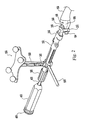
- FIGS. 1-3 An illustrative navigated stemmed implant inserter 150 is shown in FIGS. 1-3 for use with a femoral hip stem implant 100.
- the following description provides a detailed explanation of this particular illustrative example. However, this detailed description should not be taken as limiting of the scope of the invention.
- the illustrative navigated stemmed implant inserter 150 for a femoral hip stem implant 100 includes a stem engaging member 200 for engaging a portion of the hip stem implant 100, a distal housing 250, a stem locking member 300 for locking the hip stem implant 100 in engagement with the stem engaging member 200, a proximal housing 350, an actuator 400 for activating the stem locking member 300, a primary handle 450, an auxiliary handle 500, and a reference member 550 for permitting the inserter 150 to be tracked by a surgical navigation system.
- the term proximal will be used to refer to relative positions nearer the primary handle 450 and the term distal will be used to refer to relative positions further from the primary handle 450.
- the stem engaging member 200 includes a ring-shaped head 202 at its distal end having a through bore 204, a connector shaft 206 at its proximal end for engaging the distal housing 250, and a boss 208 intermediate the proximal and distal ends for engaging the distal housing 250.
- the bore 204 in the head 202 includes a lip 210.
- a protective sleeve 212 lines the bore 204 and abuts the lip 210.
- the protective sleeve 212 may be made of a material that will not mar the hip stem implant 100.
- the protective sleeve 212 may be made of a polymer such as polyetheretherketone, polyethylene, polyester, and/or other suitable materials.
- a retention plate 214 fits over the sleeve 212 to retain the sleeve 212 in the bore 204.
- the retention plate 214 is held in place with a screw 216 inserted through the plate 214 and into the head 202.
- the retention plate 214 is constrained from pivoting around the screw 216 by a pair of opposed ears 218 extending distally from the head 202.
- the connector shaft 206 includes a dimple 220 for receiving a set screw.
- the boss 208 includes a through bore 222 having a non-circular cross section for engaging the stem locking member 300.
- the through bore 222 includes a proximal counter bore 224 for receiving a portion of the distal housing 250.
- the stem engaging member 200 includes transverse holes 226 through the ring-shaped head 202 to facilitate cleaning.
- the holes 226 permit cleaning fluid to enter between the head 202 and the protective sleeve 212.
- the illustrative stem engaging member 200 is particularly suited for gripping existing hip stem implants 100 that have a neck 104 engageable by the head 202.
- the illustrative stem engaging member 200 provides a rigid connection to permit navigated insertion of stems that were not designed with navigated insertion in mind. Thus, the illustrative stem engaging member 200 may adapt older hip stem implant 100 designs to navigation.
- the distal housing 250 includes an axial through bore 252 having a longitudinal axis 254.
- the longitudinal axis 254 of the bore 252 is coincident with an inserter longitudinal axis 152.
- the bore 252 has a first, smaller, diameter near its distal end and a second, larger diameter, near its proximal end such that there is a step, or shoulder 256, formed between the proximal and distal ends.
- the distal housing 250 includes a radially outwardly extending flange 258 near its proximal end including threaded bores 260 for coupling the distal housing 250 to the proximal housing 350.
- the distal housing 250 further includes a pair of grooves 262 at its proximal end to aid in aligning the housings 250, 350 during assembly.
- the distal housing 250 is reduced in size at its distal end to form a nose 264 that engages the counter bore 224 of the boss 208 on the stem engaging member 200 to rotationally constrain the housings 250, 350 relative to one another.
- the distal housing 250 includes a radially extending boss 266 having a socket 268 the receives the connector shaft 206 of the stem engaging member 200 to couple the stem engaging member 200 to the distal housing 250.
- a transverse threaded bore 270 communicates with the socket 268 and receives a set screw 272 for securing the connector shaft 206 in the socket 268.
- the set screw aligns with the dimple 220 to positively lock the shaft 206 in the socket 268 and axially and rotationally constrain the housings 250, 350 relative to one another.
- the bores 252, 222 in the two components align to form a continuous bore.
- the stem locking member 300 includes an elongated body 302 having a distal end 304 for engaging the femoral hip stem implant 100, a proximal end 306 for engaging the actuator 400, and a radially enlarged head 308 formed adjacent the proximal end 306.
- the distal end 304 may press against a portion of the hip stem implant 100 such as the proximal body 106.
- the distal end 304 may fit within a recess 102 in hip stem implant 100.
- the distal end may be rectangular, round, elliptical, or any other suitable cross sectional shape.
- the distal end 304 has a non-circular elliptical cross section to fit an elliptical dimple 102 existing in some femoral hip stem implants 100.
- the VerSys ® Fiber Metal Taper hip stem manufactured by Zimmer, Inc. of Warsaw, Indiana includes such a dimple 102. It is advantageous for the distal end 304 to fit closely within the dimple 102 to better constrain the position of the hip stem implant 100 relative to the inserter 150.
- the head 308 includes an axially aligned dimple 312 for receiving the actuator 400.
- a spring 310 is receive over the elongated body 302 and abuts the head 308.
- the stem locking member 300 is received in the axial bore 252 of the distal housing 250 with its distal end 304 extending through the axial bore 252 of the distal housing and the non-circular bore 222 of the boss 208 on the stem engaging member 200.
- the engagement of the non-circular distal end 304 of the stem locking member with the non-circular bore 222 ensures that the distal end 304 will be rotationally aligned with the dimple 102 in the hip stem implant 100.
- the spring 310 is trapped between the head 308 of the stem locking member 300 and the shoulder 256 in the distal housing 250 and biases the stem locking member 300 proximally away from the stem engaging member 200.
- the illustrative inserter 150 is shown with the actuator 400 and stem locking member 300 being separate parts. This facilitates the alignment of a non-circular distal end 304 of the stem locking member 300 with a non-circular dimple on the illustrative hip stem implant 100. It also permits the actuator 400 to have a rotary action while the stem locking member 300 is constrained against rotation. However, in the case where the distal end 304 of the stem locking member 300 is circular or where it may otherwise be permitted to rotate relative to the distal housing 250, the actuator 400 and stem locking member 300 may be provided as a single piece and the spring 310 may be omitted.
- the proximal housing 350 includes an elongated tubular body 352 having an axial through bore 354. Threads 356 are formed in the bore 354 adjacent the distal end to engage the actuator 400.
- the proximal housing 350 includes a radially outwardly extending flange 358 near its distal end including bores 360 for coupling the proximal housing 350 to the distal housing 250.
- the proximal housing 350 further includes a pair of tabs 362 at its distal end that engage the grooves 262 of the distal housing to aid in aligning the housings 250, 350 during assembly.
- the proximal housing 350 includes opposed auxiliary handle 500 mounting fittings 364, 366 including threaded bores 368, 370.
- the handle fittings 364, 366 permit the auxiliary handle 500 to be mounted in different orientations based on surgeon preference and/or to accommodate insertion of femoral stem implants 100 in both right and left femurs.
- the proximal housing 350 includes opposed reference member 550 mounting fittings 372, 374 including spaced apart upraised sidewalls 376 defining sockets 378. Threaded bores 380 are disposed in the bottom of the sockets 378 to receive an attachment screw 382.
- the reference member fittings 372, 374 permit the reference member 550 to be mounted in different orientations based on surgeon preference and/or to accommodate insertion of femoral stem implants 100 in both right and left femurs.
- the proximal housing 350 includes threads 384 at its proximal end for engaging a locking ring 386.
- the proximal housing 350 includes slots 388 to facilitate cleaning of its interior.
- the actuator 400 includes an elongated shaft 402 having an axis 403 coincident with the inserter axis 152.
- the shaft includes threads 404 and a transverse bore 406 near its proximal end for connecting the shaft 402 to the primary handle 450.
- the shaft 402 includes threads 408 near its distal end for engaging the threads 356 near the distal end of the proximal housing 350. These threads 408, 356 convert rotary inputs to the actuator 400 into linear translation along the inserter axis 152.
- a distal tip 410 engages the dimple 312 in the head 308 of the stem locking member 300 to drive the stem locking member distally in the distal housing 250.
- the shaft includes a radially extending flange 412 for abutting the locking ring 386.
- the actuator 400 is assembled into the inserter 150 by inserting the distal tip 410 along the axial bore 354 of the proximal housing 350 until the distal actuator threads 408 abut the threads 356 of the proximal housing 350. The actuator 400 is then rotated to engage the threads 408, 356 and move the actuator distally until the distal tip 410 engages the dimple 312 in the head 308 of the stem locking member 300.
- the locking ring 386 is then threaded onto the proximal housing 350 by engaging internal locking ring threads 390 with the proximal housing threads 384.
- the locking ring 386 is advanced until a locking ring shoulder 392 engages the actuator flange 412.
- the primary handle 450 includes an exterior gripping surface 452 and an axial through bore 454.
- a transverse bore 456 communicates from the exterior gripping surface 452 to the axial bore 454.
- the handle 450 is assembled onto the actuator shaft 402 by sliding the axial bore 454 over the proximal end of the shaft 402 until the transverse bore 456 in the handle 450 aligns with the transverse bore 406 in the shaft 402.
- a pin 458 is then inserted into the bores 456, 406 to lock the handle 450 on the shaft 402.
- a strike plate 460 having a threaded bore 462 is then threaded onto the threads 404 on the proximal end of the actuator shaft 402 until the strike plate 460 abuts the proximal end of the primary handle 450.
- the handle 450 may be used to grip the inserter 150 and manipulate it relative to the surgical site.
- the handle 450 may also be rotated to move the actuator 400 relative to the proximal housing 350 to activate the stem locking member 300
- the auxiliary handle 500 includes an elongated shaft 502 having threads 504 at one end for engaging the threaded bore 368, 370 in the auxiliary handle mounting fittings 364, 366 of the proximal housing 350.
- the auxiliary handle 500 provides additional gripping options to the surgeon and permits a counter rotation force to be applied to the proximal housing 350 while the primary handle 450 is rotated to drive the actuator 400.
- the reference member 550 includes a reference member body 552 supporting reference elements 554.
- the reference member 550 includes a connecting portion (not shown) including a female dovetail opening for connecting to a male dovetail 556 on a reference member tower 558.
- the reference member tower 558 includes a through bore 560 at one end.
- the reference member tower 558 engages the socket 378 of the reference member mounting fittings 372, 374. With tower 558 engaged with the socket 378, the through bore 560 aligns with the threaded bore 380 so that the attachment screw 382 may be inserted through the through bore 560 and engaged with the threaded bore 380 to lock the tower in place.
- the neck 104 of the hip stem implant 100 is inserted into the protective sleeve 212 in the head 202 of the stem engaging member 200 until the neck 104 is pressed tightly against the sleeve 212.
- the primary handle 450 may then be rotated to turn the actuator 400 and cause it to translate distally as the actuator threads 408 engage the internal proximal housing threads 356.
- a counter torque may be applied to the proximal housing 350 to facilitate turning the primary handle 450 and actuator 400 relative to the proximal housing 350.
- the distal tip 410 of the actuator 400 presses against the stem locking member 300 and causes it to move distally.
- the stem locking member 300 compresses the spring 310 and the distal end 304 of the stem locking member 300 moves into engagement with the hip stem implant 100.
- the distal end 304 of the stem locking member 300 engages the dimple 102 in the proximal body 106 of the hip stem implant 100.
- Further tightening of the primary handle 450 causes the stem locking member 300 to press tightly against the hip stem implant 100 and lock it in position relative to the stem engaging member 200. Since the bore 204 in the head 202 of the stem engaging member 200 is angled relative to the axis 254 along which the stem locking member 300 travels, the hip stem implant 100 must move transversely to that axis 254 in order for it to be withdrawn from the stem engaging member 200.
- the hip stem implant 100 With the stem locking member 300 pressed against the hip stem implant 100, the hip stem implant 100 is prevented from moving transversely and therefore it is locked in position.
- the stem locking member 300 may press against the hip stem implant 100 to create a bending moment at the neck 104 that causes the head 202 to grip the neck 104 in a wedging grip.
- the locking ring 386 may then be tightened against the flange 412 to provide axial and frictional rotational resistance to the actuator 400 loosening in use.
- the position of the hip stem implant 100 may now be tracked by the surgical navigation system which tracks the reference elements 554 and resolves the position of the hip stem implant 100 from the known relationship between the reference elements and the hip stem implant 100.
- the hip stem implant 100 may be guided to a desired position and orientation in the femur such as to a desired depth, rotation, anterior-posterior tilt, medial-lateral tilt, and/or other position parameters of the hip stem implant 100 within the femur.
- the navigated stemmed implant inserter 150 of the present invention these parameters can be measured and adjusted.
- the femur may be prepared by broaching an opening in the femur with a rasp that also connects to a reference member 550.
- the hip stem implant may be placed in the same position as the rasp using the navigated stemmed implant inserter 150. This is particularly beneficial where the hip stem implant 100 is being press fit into the broached opening. By matching the rasp orientation, the surgeon can minimize the likelihood of splitting the femur.
- the auxiliary handle 500 may be used to rotate the hip stem implant 100 to the desired position within the femur and the strike plate 460 may be impacted to drive the hip stem implant 100 into the femur.
- the inserter 150 is disengaged from the hip stem implant 100 by loosening the locking ring 386 and then rotating the primary handle 450 to translate the actuator 400 proximally in the proximal housing 350.
- the spring 310 retracts the stem locking member 300 proximally to disengage it from the hip stem implant 100.
- the head 202 of the stem engaging member 200 may then be slipped off of the neck 104.
Landscapes
- Health & Medical Sciences (AREA)
- Transplantation (AREA)
- Orthopedic Medicine & Surgery (AREA)
- Heart & Thoracic Surgery (AREA)
- Life Sciences & Earth Sciences (AREA)
- Oral & Maxillofacial Surgery (AREA)
- Engineering & Computer Science (AREA)
- Biomedical Technology (AREA)
- Physical Education & Sports Medicine (AREA)
- Vascular Medicine (AREA)
- Cardiology (AREA)
- Animal Behavior & Ethology (AREA)
- General Health & Medical Sciences (AREA)
- Public Health (AREA)
- Veterinary Medicine (AREA)
- Prostheses (AREA)
- Surgical Instruments (AREA)
Claims (13)
- Dispositif d'insertion navigué d'un implant à tige (150) pour une utilisation avec un implant orthopédique à tige (100) et un système de navigation chirurgical durant une chirurgie de remplacement articulaire sur un os, le dispositif d'insertion (150) comprenant :un organe d'engagement de tige (200) pouvant être engagé avec l'implant orthopédique à tige (100) dans un agencement relatif rigide et incluant une tête en forme d'anneau (202) ayant un alésage (204) avec un axe d'alésage pour recevoir un col (104) de l'implant orthopédique à tige (100);un organe de référence (550) pouvant être suivi par le système de navigation chirurgical, l'organe de référence (550) étant soutenu dans une relation rigide connue à l'implant orthopédique à tige (100) de telle sorte que le système de navigation chirurgical puisse déterminer la position et l'orientation de l'implant orthopédique à tige (100) par rapport à l'os par la détection de la position et de l'orientation de l'organe de référence (550) et la résolution de la position et de l'orientation de l'implant orthopédique à tige (100) d'après une relation connue entre l'organe de référence (550) et l'implant orthopédique à tige (100);un organe de verrouillage de tige (300) monté au dispositif d'insertion pour une translation le long d'un axe de verrouillage de tige (254) transversal à l'axe d'alésage de la tête (202), l'organe de verrouillage de tige (300) étant mobile entre une première position dans laquelle le col (104) de l'implant orthopédique à tige (100) peut être dégagé de la tête (202) et une deuxième position dans laquelle le col (104) ne peut pas être dégagé de la tête (202) ; etun actionneur (400) monté au dispositif d'insertion (150) pour une rotation et une translation le long de l'axe de verrouillage de tige (254), l'actionneur (400) étant capable de convertir une entrée en rotation à l'actionneur (400) en un mouvement linéaire pour déplacer l'organe de verrouillage de tige (300) de la première position à la deuxième position, où l'actionneur (400) inclut une portion de butée de l'anneau de verrouillage (412) et le dispositif d'insertion d'un implant à tige (150) comprend en plus un anneau de verrouillage (386) vissé sur le dispositif d'insertion (150), l'anneau de verrouillage (386) étant mobile entre une première position dans laquelle il est espacé de la portion de butée de l'anneau de verrouillage (412) et une deuxième position dans laquelle il vient en butée contre la portion de butée de l'anneau de verrouillage (412).
- Dispositif d'insertion navigué d'un implant à tige (150) de la revendication 1 caractérisé en ce que l'organe de référence (550) est détectable en utilisant une technologie de détection sélectionnée parmi le groupe consistant en une technologie de type électromagnétique, acoustique, et d'imagerie.
- Dispositif d'insertion navigué d'un implant à tige (150) de la revendication 2 caractérisé en ce que l'organe de référence (550) produit activement un signal détectable par le système de navigation chirurgical.
- Dispositif d'insertion navigué d'un implant à tige (150) de la revendication 2 caractérisé en ce que l'organe de référence (550) est détecté passivement par le système de navigation chirurgical.
- Dispositif d'insertion navigué d'un implant à tige (150) de l'une quelconque des revendications précédentes caractérisé en ce que le système de navigation chirurgical est capable de résoudre et d'afficher un ou plusieurs paramètres de position de l'implant orthopédique à tige (100) par rapport à l'os sélectionné(s) à partir de la liste consistant en une profondeur, une rotation, une inclinaison antérieure-postérieure, et une inclinaison médiale-latérale.
- Dispositif d'insertion navigué d'un implant à tige (150) de l'une quelconque des revendications précédentes caractérisé en ce que la tête (202) inclut un manchon (212) disposé dans l'alésage (204) pour isoler l'implant orthopédique à tige (100) de la tête (202).
- Dispositif d'insertion navigué d'un implant à tige (150) de la revendication 6 caractérisé en ce que le manchon (212) comprend un polymère.
- Dispositif d'insertion navigué d'un implant à tige (150) de la revendication 6 ou 7 comprenant en plus une plaque de retenue (214) disposée sur le manchon (212) pour retenir le manchon (212) dans l'alésage (204).
- Dispositif d'insertion navigué d'un implant à tige (150) de l'une quelconque des revendications précédentes caractérisé en ce que l'organe de verrouillage de tige (300) et l'actionneur (400) sont des organes allongés séparés alignés coaxialement l'un avec l'autre, le dispositif d'insertion (150) comprenant en plus un ressort (310) monté de manière adjacente à l'organe de verrouillage de tige (300) pour maintenir l'organe de verrouillage de tige (300) vers l'actionneur (400).
- Dispositif d'insertion navigué d'un implant à tige (150) de l'une quelconque des revendications précédentes caractérisé en ce que la portion de butée de l'anneau de verrouillage (412) comprend une bride s'étendant radialement.
- Dispositif d'insertion navigué d'un implant à tige (150) de l'une quelconque des revendications précédentes comprenant en plus une poignée auxiliaire (500) montée de manière transversale à l'axe de verrouillage de tige (254).
- Dispositif d'insertion navigué d'un implant à tige (150) de la revendication 11 comprenant en plus une pluralité d'accessoires de montage de poignée (364, 366) de telle sorte que la poignée (500) puisse être montée dans une pluralité de positions transversales à l'axe de l'actionneur.
- Dispositif d'insertion navigué d'un implant à tige (150) de l'une quelconque des revendications précédentes caractérisé en ce que le dispositif d'insertion (150) inclut une pluralité d'accessoires de montage de l'organe de référence (372, 374) de telle sorte que l'organe de référence (550) puisse être monté dans une pluralité de positions.
Applications Claiming Priority (2)
| Application Number | Priority Date | Filing Date | Title |
|---|---|---|---|
| US795837 | 2004-03-08 | ||
| US10/795,837 US20050203539A1 (en) | 2004-03-08 | 2004-03-08 | Navigated stemmed orthopaedic implant inserter |
Publications (2)
| Publication Number | Publication Date |
|---|---|
| EP1574186A1 EP1574186A1 (fr) | 2005-09-14 |
| EP1574186B1 true EP1574186B1 (fr) | 2008-06-04 |
Family
ID=34827599
Family Applications (1)
| Application Number | Title | Priority Date | Filing Date |
|---|---|---|---|
| EP05251376A Not-in-force EP1574186B1 (fr) | 2004-03-08 | 2005-03-08 | Dispositif d'insertion navigué pour implants orthopédiques à tiges |
Country Status (7)
| Country | Link |
|---|---|
| US (1) | US20050203539A1 (fr) |
| EP (1) | EP1574186B1 (fr) |
| JP (1) | JP2005253967A (fr) |
| AT (1) | ATE397428T1 (fr) |
| AU (1) | AU2005200970A1 (fr) |
| CA (1) | CA2491792C (fr) |
| DE (1) | DE602005007282D1 (fr) |
Cited By (3)
| Publication number | Priority date | Publication date | Assignee | Title |
|---|---|---|---|---|
| US8571628B2 (en) | 2002-03-06 | 2013-10-29 | Mako Surgical Corp. | Apparatus and method for haptic rendering |
| US9492237B2 (en) | 2006-05-19 | 2016-11-15 | Mako Surgical Corp. | Method and apparatus for controlling a haptic device |
| US10058392B2 (en) | 2002-03-06 | 2018-08-28 | Mako Surgical Corp. | Neural monitor-based dynamic boundaries |
Families Citing this family (33)
| Publication number | Priority date | Publication date | Assignee | Title |
|---|---|---|---|---|
| AU2003218010A1 (en) | 2002-03-06 | 2003-09-22 | Z-Kat, Inc. | System and method for using a haptic device in combination with a computer-assisted surgery system |
| US11202676B2 (en) | 2002-03-06 | 2021-12-21 | Mako Surgical Corp. | Neural monitor-based dynamic haptics |
| EP1652479B1 (fr) * | 2004-10-27 | 2008-02-20 | BrainLAB AG | Ecarteur vertébral avec des indicateurs de position |
| FR2890851B1 (fr) * | 2005-09-21 | 2008-06-20 | Abbott Spine Sa | Ancillaire de mise en tension d'un lien souple. |
| KR100745841B1 (ko) | 2006-06-14 | 2007-08-02 | 주식회사 사이버메드 | 수술용 항법 장치를 위한 유니버설 트랙커 어댑터 |
| DE602006018666D1 (de) * | 2006-08-15 | 2011-01-13 | Ao Technology Ag | Vorrichtung für die computergestützte distale arretierung von marknägeln und verfahren für die lokalisierung der distalen verriegelungslöcher von marknägeln |
| US8603099B2 (en) | 2006-09-26 | 2013-12-10 | DePuy Synthes Products, LLC | Force dissipating impactor device |
| US8543188B2 (en) * | 2006-10-17 | 2013-09-24 | General Electric Company | Method and apparatus for calibrating medical devices |
| US20080269765A1 (en) * | 2007-04-27 | 2008-10-30 | Zimmer, Inc. | Instrument and method for implanting a prosthetic component |
| US20090099566A1 (en) * | 2007-10-10 | 2009-04-16 | Maness Megan A | Modular stem inserter |
| CN102018554B (zh) * | 2009-09-17 | 2013-01-09 | 北京市春立正达医疗器械股份有限公司 | 髋关节股骨柄持柄器 |
| US8545505B2 (en) | 2010-01-15 | 2013-10-01 | Pioneer Surgical Technology, Inc. | Low friction rod persuader |
| US8679130B2 (en) | 2010-03-05 | 2014-03-25 | Biomet Manufacturing, Llc | Guide assembly for lateral implants and associated methods |
| US8529569B2 (en) | 2010-03-05 | 2013-09-10 | Biomet Manufacturing, Llc | Method and apparatus for preparing a proximal femur |
| US8221432B2 (en) * | 2010-03-05 | 2012-07-17 | Biomet Manufacturing Corp. | Method and apparatus for implanting a modular femoral hip |
| US8419743B2 (en) * | 2010-03-05 | 2013-04-16 | Biomet Manufacturing Corp. | Assembly tool for modular implants and associated method |
| US8333807B2 (en) | 2010-03-05 | 2012-12-18 | Biomet Manufacturing Corp. | Method and apparatus for trialing and implanting a modular femoral hip |
| US8460393B2 (en) | 2010-03-05 | 2013-06-11 | Biomet Manufacturing Corp. | Modular lateral hip augments |
| US9161799B2 (en) * | 2013-01-28 | 2015-10-20 | Warsaw Orthopedic, Inc. | Surgical implant system and method |
| US10456264B2 (en) | 2014-01-24 | 2019-10-29 | Tornier, Inc. | Humeral implant anchor system |
| US10405911B2 (en) * | 2015-03-19 | 2019-09-10 | Louis FERREIRA | Long stem implant extraction tool |
| US10463499B2 (en) | 2016-03-25 | 2019-11-05 | Tornier, Inc. | Stemless shoulder implant with fixation components |
| US11129724B2 (en) | 2016-07-28 | 2021-09-28 | Howmedica Osteonics Corp. | Stemless prosthesis anchor component |
| US10722223B2 (en) | 2017-05-31 | 2020-07-28 | Medos International Sarl | Coupling devices for surgical instruments and related methods |
| US11117197B2 (en) | 2017-05-31 | 2021-09-14 | Medos International Sarl | Instrument couplings and related methods |
| WO2019038203A1 (fr) * | 2017-08-21 | 2019-02-28 | Depuy Ireland Unlimited Company | Guide, kit de pièces et ensemble de guidage pour une chirurgie de la hanche |
| CA3076502A1 (fr) | 2017-09-25 | 2019-03-28 | Tornier, Inc. | Composants d'ancrage de prothese sans tige specifique au patient |
| US10731687B2 (en) | 2017-11-22 | 2020-08-04 | Medos International Sarl | Instrument coupling interfaces and related methods |
| GB201901590D0 (en) * | 2019-02-05 | 2019-03-27 | Smith & Nephew Orthopaedics Ag | Robust impactor |
| AU2020360410B2 (en) * | 2019-10-01 | 2023-03-02 | Howmedica Osteonics Corp. | Shoulder prosthesis components and assemblies |
| US11644053B2 (en) | 2019-11-26 | 2023-05-09 | Medos International Sarl | Instrument coupling interfaces and related methods |
| WO2023015243A2 (fr) * | 2021-08-04 | 2023-02-09 | University Of Florida Research Foundation, Incorporated | Appareil de réseau de référence pour système de navigation neurochirurgical |
| CN117462204B (zh) * | 2023-12-22 | 2024-04-30 | 北京爱康宜诚医疗器材有限公司 | 髋臼锉 |
Citations (1)
| Publication number | Priority date | Publication date | Assignee | Title |
|---|---|---|---|---|
| EP0207873A1 (fr) * | 1985-06-24 | 1987-01-07 | Equipement Medical Et Chirurgical De L'ouest | Instrument porte-prothèse |
Family Cites Families (58)
| Publication number | Priority date | Publication date | Assignee | Title |
|---|---|---|---|---|
| CH490076A (de) * | 1968-04-25 | 1970-05-15 | Arnold Heinrich Dr Med Huggler | Instrument zur Verwendung mit einer Gelenkkopfprothese für den Oberschenkelknochen |
| US3855569A (en) * | 1973-05-07 | 1974-12-17 | Marlin Mfg Corp | Thermocouple terminal connector |
| US4135517A (en) * | 1977-07-21 | 1979-01-23 | Minnesota Mining And Manufacturing Company | Femoral prosthesis trial fitting device |
| DE3103954A1 (de) * | 1981-02-05 | 1982-09-02 | Lemförder Metallwaren AG, 2844 Lemförde | Kugelgelenk |
| US4552136A (en) * | 1983-10-19 | 1985-11-12 | Howmedica, Inc. | Femoral rasp |
| US4716894A (en) * | 1986-08-27 | 1988-01-05 | Zimmer, Inc. | Acetabular cup inserting instrument |
| US4765328A (en) * | 1987-08-10 | 1988-08-23 | Osteonics Corp. | Surgical instrument handle coupling |
| US5089004A (en) * | 1988-01-19 | 1992-02-18 | Osteonics Corp. | Prosthetic implant procedure and femoral broach therefor |
| US5251127A (en) * | 1988-02-01 | 1993-10-05 | Faro Medical Technologies Inc. | Computer-aided surgery apparatus |
| US4979949A (en) * | 1988-04-26 | 1990-12-25 | The Board Of Regents Of The University Of Washington | Robot-aided system for surgery |
| US4903692A (en) * | 1989-05-08 | 1990-02-27 | Reese Hewitt W | Bone clamp installation tool |
| US5037424A (en) * | 1989-12-21 | 1991-08-06 | Aboczsky Robert I | Instrument for orienting, inserting and impacting an acetabular cup prosthesis |
| US5089003A (en) * | 1989-12-22 | 1992-02-18 | Zimmer, Inc. | Rasp tool including detachable handle member |
| US5147366A (en) * | 1990-03-01 | 1992-09-15 | Pfizer Hospital Products Group, Inc. | Pressurization of bone cement surrounding an endoprosthesis |
| US5086401A (en) * | 1990-05-11 | 1992-02-04 | International Business Machines Corporation | Image-directed robotic system for precise robotic surgery including redundant consistency checking |
| US5156626A (en) * | 1990-06-29 | 1992-10-20 | Zimmer, Inc. | Set of provisional prosthesis instrumentation |
| US5190550A (en) * | 1990-08-02 | 1993-03-02 | Exactech, Inc. | Locking surgical tool handle system |
| US5061270A (en) * | 1991-03-18 | 1991-10-29 | Aboczky Robert I | System for orienting, inserting and impacting an acetabular cup prosthesis |
| US5064427A (en) * | 1991-05-14 | 1991-11-12 | Intermedics Orthopedics, Inc. | Apparatus for inserting and withdrawing humeral prosthesis |
| US5284483A (en) * | 1992-09-16 | 1994-02-08 | Zimmer, Inc. | Acetabular cup inserting instrument |
| SE9203579L (sv) * | 1992-11-26 | 1994-05-27 | Gustaf Gadelius | Sätt att bestämma ett lårbens läge i förhållande till ett bäckenben i samband med en höftledsoperation |
| US5342363A (en) * | 1992-11-30 | 1994-08-30 | Wright Medical Technology, Inc. | Medical instrument and procedure |
| US5320625A (en) * | 1993-01-21 | 1994-06-14 | Bertin Kim C | Apparatus and method for implanting a prosthetic acetabular cup and then testing the stability of the implant |
| DE59309665D1 (de) * | 1993-04-07 | 1999-07-29 | Sulzer Orthopaedie Ag | Raspel und ein damit kuppelbares Griffteil zum Vorbereiten eines Röhrenknochens für den Einsatz einer Prothese |
| US5364403A (en) * | 1993-09-20 | 1994-11-15 | Zimmer, Inc. | Acetabular cup positioner |
| US5954727A (en) * | 1993-10-29 | 1999-09-21 | Howmedica Inc. | Acetabular cup positioning tool and method of positioning an acetabular cup |
| GB9322383D0 (en) * | 1993-10-29 | 1993-12-15 | Howmedica | Method and apparatus for implanting an acetabular cup |
| US5658294A (en) * | 1993-12-02 | 1997-08-19 | Sulzer Orthopedics Inc. | Instrument for holding an acetabular cup |
| US5490852A (en) * | 1994-02-16 | 1996-02-13 | Azer; Samir N. | Orthopedic awl |
| US5738586A (en) * | 1994-09-09 | 1998-04-14 | Consolidated Devices Inc. | Semi-universal torque coupling |
| US5474560A (en) * | 1994-09-26 | 1995-12-12 | Zimmer, Inc. | Prosthetic acetabular cup inserter |
| DE69528998T2 (de) * | 1994-10-07 | 2003-07-03 | St Louis University St Louis | Chirurgische navigationsanordnung einschliesslich referenz- und ortungssystemen |
| US5578037A (en) * | 1994-11-14 | 1996-11-26 | Johnson & Johnson Professional, Inc. | Surgical guide for femoral resection |
| US5624447A (en) * | 1995-03-20 | 1997-04-29 | Othy, Inc. | Surgical tool guide and entry hole positioner |
| US5571111A (en) * | 1995-05-01 | 1996-11-05 | Aboczky; Robert I. | Instrument for orienting, inserting and impacting an acetabular cup prosthesis including prosthesis retaining head arrangement |
| US5682886A (en) * | 1995-12-26 | 1997-11-04 | Musculographics Inc | Computer-assisted surgical system |
| US5683395A (en) * | 1996-04-26 | 1997-11-04 | Mikhail; W. E. Michael | System for performing hip prothesis revision surgery |
| US5885295A (en) * | 1996-08-07 | 1999-03-23 | Biomet, Inc. | Apparatus and method for positioning an orthopedic implant |
| US6063088A (en) * | 1997-03-24 | 2000-05-16 | United States Surgical Corporation | Method and instrumentation for implant insertion |
| US5921992A (en) * | 1997-04-11 | 1999-07-13 | Radionics, Inc. | Method and system for frameless tool calibration |
| US5834759A (en) * | 1997-05-22 | 1998-11-10 | Glossop; Neil David | Tracking device having emitter groups with different emitting directions |
| ATE230247T1 (de) * | 1997-07-04 | 2003-01-15 | Sulzer Orthopaedie Ag | Instrument zum einbringen eines einsatzes eines implantats in die zugehörige schale |
| US6348058B1 (en) * | 1997-12-12 | 2002-02-19 | Surgical Navigation Technologies, Inc. | Image guided spinal surgery guide, system, and method for use thereof |
| DE69913012T2 (de) * | 1998-03-02 | 2004-04-15 | Benoist Girard Sas | Prothesen-Einsetzvorrichtung |
| GB9804473D0 (en) * | 1998-03-02 | 1998-04-29 | Benoist Girard & Cie | Prosthesis inserter |
| DE29807671U1 (de) * | 1998-04-28 | 1999-09-02 | Link Waldemar Gmbh Co | Chirurgisches Instrument |
| US5997582A (en) * | 1998-05-01 | 1999-12-07 | Weiss; James M. | Hip replacement methods and apparatus |
| US5951561A (en) * | 1998-06-30 | 1999-09-14 | Smith & Nephew, Inc. | Minimally invasive intramedullary nail insertion instruments and method |
| US6338716B1 (en) * | 1999-11-24 | 2002-01-15 | Acuson Corporation | Medical diagnostic ultrasonic transducer probe and imaging system for use with a position and orientation sensor |
| US6497134B1 (en) * | 2000-03-15 | 2002-12-24 | Image Guided Technologies, Inc. | Calibration of an instrument |
| US6395005B1 (en) * | 2000-04-14 | 2002-05-28 | Howmedica Osteonics Corp. | Acetabular alignment apparatus and method |
| US6991656B2 (en) * | 2000-04-26 | 2006-01-31 | Dana Mears | Method and apparatus for performing a minimally invasive total hip arthroplasty |
| US6490475B1 (en) * | 2000-04-28 | 2002-12-03 | Ge Medical Systems Global Technology Company, Llc | Fluoroscopic tracking and visualization system |
| DE20021494U1 (de) * | 2000-12-20 | 2001-03-29 | Depuy Orthopaedie Gmbh | Führungsvorrichtung für einen Knochenfräser oder Protheseneinschläger |
| ES2241915T3 (es) * | 2002-03-21 | 2005-11-01 | Brainlab Ag | Dispositivo de navegacion para un retractor. |
| WO2003096920A1 (fr) * | 2002-05-21 | 2003-11-27 | Plus Endoprothetik Ag | Ensemble permettant de determiner des dimensions geometriques, a definition de fonction, d'une articulation d'un vertebre |
| DE10306793A1 (de) * | 2002-05-21 | 2003-12-04 | Plus Endoprothetik Ag Rotkreuz | Anordnung und Verfahren zur intraoperativen Festlegung der Lage eines Gelenkersatzimplantats |
| US7166114B2 (en) * | 2002-09-18 | 2007-01-23 | Stryker Leibinger Gmbh & Co Kg | Method and system for calibrating a surgical tool and adapter thereof |
-
2004
- 2004-03-08 US US10/795,837 patent/US20050203539A1/en not_active Abandoned
-
2005
- 2005-01-10 CA CA2491792A patent/CA2491792C/fr not_active Expired - Fee Related
- 2005-03-03 AU AU2005200970A patent/AU2005200970A1/en not_active Abandoned
- 2005-03-07 JP JP2005062367A patent/JP2005253967A/ja active Pending
- 2005-03-08 DE DE602005007282T patent/DE602005007282D1/de active Active
- 2005-03-08 AT AT05251376T patent/ATE397428T1/de not_active IP Right Cessation
- 2005-03-08 EP EP05251376A patent/EP1574186B1/fr not_active Not-in-force
Patent Citations (1)
| Publication number | Priority date | Publication date | Assignee | Title |
|---|---|---|---|---|
| EP0207873A1 (fr) * | 1985-06-24 | 1987-01-07 | Equipement Medical Et Chirurgical De L'ouest | Instrument porte-prothèse |
Cited By (7)
| Publication number | Priority date | Publication date | Assignee | Title |
|---|---|---|---|---|
| US8571628B2 (en) | 2002-03-06 | 2013-10-29 | Mako Surgical Corp. | Apparatus and method for haptic rendering |
| US8911499B2 (en) | 2002-03-06 | 2014-12-16 | Mako Surgical Corp. | Haptic guidance method |
| US10058392B2 (en) | 2002-03-06 | 2018-08-28 | Mako Surgical Corp. | Neural monitor-based dynamic boundaries |
| US10231790B2 (en) | 2002-03-06 | 2019-03-19 | Mako Surgical Corp. | Haptic guidance system and method |
| US9492237B2 (en) | 2006-05-19 | 2016-11-15 | Mako Surgical Corp. | Method and apparatus for controlling a haptic device |
| US10028789B2 (en) | 2006-05-19 | 2018-07-24 | Mako Surgical Corp. | Method and apparatus for controlling a haptic device |
| US11844577B2 (en) | 2006-05-19 | 2023-12-19 | Mako Surgical Corp. | System and method for verifying calibration of a surgical system |
Also Published As
| Publication number | Publication date |
|---|---|
| AU2005200970A1 (en) | 2005-09-22 |
| EP1574186A1 (fr) | 2005-09-14 |
| DE602005007282D1 (de) | 2008-07-17 |
| US20050203539A1 (en) | 2005-09-15 |
| JP2005253967A (ja) | 2005-09-22 |
| CA2491792C (fr) | 2011-03-15 |
| CA2491792A1 (fr) | 2005-09-08 |
| ATE397428T1 (de) | 2008-06-15 |
Similar Documents
| Publication | Publication Date | Title |
|---|---|---|
| EP1574186B1 (fr) | Dispositif d'insertion navigué pour implants orthopédiques à tiges | |
| US7634306B2 (en) | Non-image, computer assisted navigation system for joint replacement surgery with modular implant system | |
| EP1561438A2 (fr) | Dispositif d'insertion d'un élément orthopédique à utiliser avec un système de guidage chirurgical | |
| EP1853181B1 (fr) | Outils de reperage de remplacement de l'epaule assiste par ordinateur | |
| US7241298B2 (en) | Universal alignment guide | |
| EP1482853B1 (fr) | Systeme de navigation sans imagerie assiste par ordinateur concu pour des operations chirurgicales de remplacement de la hanche | |
| CA2537594C (fr) | Dispositif, procede et systeme destines a la numerisation d'informations relatives a la position et a l'orientation de composantes d'une prothese de la hanche | |
| US20060015018A1 (en) | CAS modular body reference and limb position measurement system | |
| EP1574177A1 (fr) | Instrument de navigation pour le fémur | |
| US20070225725A1 (en) | Modular acetabular component inserter | |
| EP1570791A1 (fr) | Système de guidage pour instrument chirurgical rotatif | |
| US20050021037A1 (en) | Image-guided navigated precision reamers | |
| US20030105470A1 (en) | Apparatus and methods for making intraoperative orthopedic measurements | |
| EP1574171A1 (fr) | Guide orthopédique navigué | |
| US20070287910A1 (en) | Quick Disconnect and Repositionable Reference Frame for Computer Assisted Surgery | |
| US20040068263A1 (en) | CAS bone reference with articulated support | |
| US11944326B2 (en) | Systems and methods for transcorporeal microdecompression | |
| US7749223B2 (en) | Navigated femoral axis finder | |
| US11911112B2 (en) | Robotic navigational system | |
| WO2007053780A1 (fr) | Pince de fixation de fil differentielle | |
| AU2012200184A1 (en) | Quick disconnect and repositionable reference frame for computer assisted surgery |
Legal Events
| Date | Code | Title | Description |
|---|---|---|---|
| PUAI | Public reference made under article 153(3) epc to a published international application that has entered the european phase |
Free format text: ORIGINAL CODE: 0009012 |
|
| AK | Designated contracting states |
Kind code of ref document: A1 Designated state(s): AT BE BG CH CY CZ DE DK EE ES FI FR GB GR HU IE IS IT LI LT LU MC NL PL PT RO SE SI SK TR |
|
| AX | Request for extension of the european patent |
Extension state: AL BA HR LV MK YU |
|
| 17P | Request for examination filed |
Effective date: 20060228 |
|
| AKX | Designation fees paid |
Designated state(s): AT BE BG CH CY CZ DE DK EE ES FI FR GB GR HU IE IS IT LI LT LU MC NL PL PT RO SE SI SK TR |
|
| 17Q | First examination report despatched |
Effective date: 20060407 |
|
| GRAP | Despatch of communication of intention to grant a patent |
Free format text: ORIGINAL CODE: EPIDOSNIGR1 |
|
| GRAS | Grant fee paid |
Free format text: ORIGINAL CODE: EPIDOSNIGR3 |
|
| RAP1 | Party data changed (applicant data changed or rights of an application transferred) |
Owner name: ZIMMER TECHNOLOGY, INC. |
|
| GRAA | (expected) grant |
Free format text: ORIGINAL CODE: 0009210 |
|
| AK | Designated contracting states |
Kind code of ref document: B1 Designated state(s): AT BE BG CH CY CZ DE DK EE ES FI FR GB GR HU IE IS IT LI LT LU MC NL PL PT RO SE SI SK TR |
|
| REG | Reference to a national code |
Ref country code: GB Ref legal event code: FG4D |
|
| REG | Reference to a national code |
Ref country code: CH Ref legal event code: EP |
|
| REF | Corresponds to: |
Ref document number: 602005007282 Country of ref document: DE Date of ref document: 20080717 Kind code of ref document: P |
|
| REG | Reference to a national code |
Ref country code: IE Ref legal event code: FG4D |
|
| PG25 | Lapsed in a contracting state [announced via postgrant information from national office to epo] |
Ref country code: SI Free format text: LAPSE BECAUSE OF FAILURE TO SUBMIT A TRANSLATION OF THE DESCRIPTION OR TO PAY THE FEE WITHIN THE PRESCRIBED TIME-LIMIT Effective date: 20080604 Ref country code: FI Free format text: LAPSE BECAUSE OF FAILURE TO SUBMIT A TRANSLATION OF THE DESCRIPTION OR TO PAY THE FEE WITHIN THE PRESCRIBED TIME-LIMIT Effective date: 20080604 Ref country code: ES Free format text: LAPSE BECAUSE OF FAILURE TO SUBMIT A TRANSLATION OF THE DESCRIPTION OR TO PAY THE FEE WITHIN THE PRESCRIBED TIME-LIMIT Effective date: 20080915 |
|
| PG25 | Lapsed in a contracting state [announced via postgrant information from national office to epo] |
Ref country code: PL Free format text: LAPSE BECAUSE OF FAILURE TO SUBMIT A TRANSLATION OF THE DESCRIPTION OR TO PAY THE FEE WITHIN THE PRESCRIBED TIME-LIMIT Effective date: 20080604 Ref country code: NL Free format text: LAPSE BECAUSE OF FAILURE TO SUBMIT A TRANSLATION OF THE DESCRIPTION OR TO PAY THE FEE WITHIN THE PRESCRIBED TIME-LIMIT Effective date: 20080604 Ref country code: AT Free format text: LAPSE BECAUSE OF FAILURE TO SUBMIT A TRANSLATION OF THE DESCRIPTION OR TO PAY THE FEE WITHIN THE PRESCRIBED TIME-LIMIT Effective date: 20080604 |
|
| NLV1 | Nl: lapsed or annulled due to failure to fulfill the requirements of art. 29p and 29m of the patents act | ||
| PG25 | Lapsed in a contracting state [announced via postgrant information from national office to epo] |
Ref country code: LT Free format text: LAPSE BECAUSE OF FAILURE TO SUBMIT A TRANSLATION OF THE DESCRIPTION OR TO PAY THE FEE WITHIN THE PRESCRIBED TIME-LIMIT Effective date: 20080604 Ref country code: SE Free format text: LAPSE BECAUSE OF FAILURE TO SUBMIT A TRANSLATION OF THE DESCRIPTION OR TO PAY THE FEE WITHIN THE PRESCRIBED TIME-LIMIT Effective date: 20080904 Ref country code: IS Free format text: LAPSE BECAUSE OF FAILURE TO SUBMIT A TRANSLATION OF THE DESCRIPTION OR TO PAY THE FEE WITHIN THE PRESCRIBED TIME-LIMIT Effective date: 20081004 Ref country code: CZ Free format text: LAPSE BECAUSE OF FAILURE TO SUBMIT A TRANSLATION OF THE DESCRIPTION OR TO PAY THE FEE WITHIN THE PRESCRIBED TIME-LIMIT Effective date: 20080604 |
|
| PG25 | Lapsed in a contracting state [announced via postgrant information from national office to epo] |
Ref country code: SK Free format text: LAPSE BECAUSE OF FAILURE TO SUBMIT A TRANSLATION OF THE DESCRIPTION OR TO PAY THE FEE WITHIN THE PRESCRIBED TIME-LIMIT Effective date: 20080604 Ref country code: RO Free format text: LAPSE BECAUSE OF FAILURE TO SUBMIT A TRANSLATION OF THE DESCRIPTION OR TO PAY THE FEE WITHIN THE PRESCRIBED TIME-LIMIT Effective date: 20080604 Ref country code: BE Free format text: LAPSE BECAUSE OF FAILURE TO SUBMIT A TRANSLATION OF THE DESCRIPTION OR TO PAY THE FEE WITHIN THE PRESCRIBED TIME-LIMIT Effective date: 20080604 Ref country code: PT Free format text: LAPSE BECAUSE OF FAILURE TO SUBMIT A TRANSLATION OF THE DESCRIPTION OR TO PAY THE FEE WITHIN THE PRESCRIBED TIME-LIMIT Effective date: 20081104 |
|
| PLBE | No opposition filed within time limit |
Free format text: ORIGINAL CODE: 0009261 |
|
| STAA | Information on the status of an ep patent application or granted ep patent |
Free format text: STATUS: NO OPPOSITION FILED WITHIN TIME LIMIT |
|
| PG25 | Lapsed in a contracting state [announced via postgrant information from national office to epo] |
Ref country code: EE Free format text: LAPSE BECAUSE OF FAILURE TO SUBMIT A TRANSLATION OF THE DESCRIPTION OR TO PAY THE FEE WITHIN THE PRESCRIBED TIME-LIMIT Effective date: 20080604 Ref country code: BG Free format text: LAPSE BECAUSE OF FAILURE TO SUBMIT A TRANSLATION OF THE DESCRIPTION OR TO PAY THE FEE WITHIN THE PRESCRIBED TIME-LIMIT Effective date: 20080904 Ref country code: DK Free format text: LAPSE BECAUSE OF FAILURE TO SUBMIT A TRANSLATION OF THE DESCRIPTION OR TO PAY THE FEE WITHIN THE PRESCRIBED TIME-LIMIT Effective date: 20080604 |
|
| 26N | No opposition filed |
Effective date: 20090305 |
|
| PG25 | Lapsed in a contracting state [announced via postgrant information from national office to epo] |
Ref country code: MC Free format text: LAPSE BECAUSE OF NON-PAYMENT OF DUE FEES Effective date: 20090331 |
|
| REG | Reference to a national code |
Ref country code: CH Ref legal event code: PL |
|
| PG25 | Lapsed in a contracting state [announced via postgrant information from national office to epo] |
Ref country code: IE Free format text: LAPSE BECAUSE OF NON-PAYMENT OF DUE FEES Effective date: 20090308 Ref country code: LI Free format text: LAPSE BECAUSE OF NON-PAYMENT OF DUE FEES Effective date: 20090331 Ref country code: CH Free format text: LAPSE BECAUSE OF NON-PAYMENT OF DUE FEES Effective date: 20090331 |
|
| PG25 | Lapsed in a contracting state [announced via postgrant information from national office to epo] |
Ref country code: GR Free format text: LAPSE BECAUSE OF FAILURE TO SUBMIT A TRANSLATION OF THE DESCRIPTION OR TO PAY THE FEE WITHIN THE PRESCRIBED TIME-LIMIT Effective date: 20080905 |
|
| PG25 | Lapsed in a contracting state [announced via postgrant information from national office to epo] |
Ref country code: LU Free format text: LAPSE BECAUSE OF NON-PAYMENT OF DUE FEES Effective date: 20090308 |
|
| PGFP | Annual fee paid to national office [announced via postgrant information from national office to epo] |
Ref country code: FR Payment date: 20110304 Year of fee payment: 7 Ref country code: IT Payment date: 20110319 Year of fee payment: 7 |
|
| PG25 | Lapsed in a contracting state [announced via postgrant information from national office to epo] |
Ref country code: HU Free format text: LAPSE BECAUSE OF FAILURE TO SUBMIT A TRANSLATION OF THE DESCRIPTION OR TO PAY THE FEE WITHIN THE PRESCRIBED TIME-LIMIT Effective date: 20081205 |
|
| PG25 | Lapsed in a contracting state [announced via postgrant information from national office to epo] |
Ref country code: TR Free format text: LAPSE BECAUSE OF FAILURE TO SUBMIT A TRANSLATION OF THE DESCRIPTION OR TO PAY THE FEE WITHIN THE PRESCRIBED TIME-LIMIT Effective date: 20080604 |
|
| PG25 | Lapsed in a contracting state [announced via postgrant information from national office to epo] |
Ref country code: CY Free format text: LAPSE BECAUSE OF FAILURE TO SUBMIT A TRANSLATION OF THE DESCRIPTION OR TO PAY THE FEE WITHIN THE PRESCRIBED TIME-LIMIT Effective date: 20080604 |
|
| REG | Reference to a national code |
Ref country code: FR Ref legal event code: ST Effective date: 20121130 |
|
| PG25 | Lapsed in a contracting state [announced via postgrant information from national office to epo] |
Ref country code: FR Free format text: LAPSE BECAUSE OF NON-PAYMENT OF DUE FEES Effective date: 20120402 |
|
| PG25 | Lapsed in a contracting state [announced via postgrant information from national office to epo] |
Ref country code: IT Free format text: LAPSE BECAUSE OF NON-PAYMENT OF DUE FEES Effective date: 20120308 |
|
| PGFP | Annual fee paid to national office [announced via postgrant information from national office to epo] |
Ref country code: DE Payment date: 20130306 Year of fee payment: 9 |
|
| REG | Reference to a national code |
Ref country code: DE Ref legal event code: R119 Ref document number: 602005007282 Country of ref document: DE |
|
| REG | Reference to a national code |
Ref country code: DE Ref legal event code: R119 Ref document number: 602005007282 Country of ref document: DE Effective date: 20141001 |
|
| PG25 | Lapsed in a contracting state [announced via postgrant information from national office to epo] |
Ref country code: DE Free format text: LAPSE BECAUSE OF NON-PAYMENT OF DUE FEES Effective date: 20141001 |
|
| PGFP | Annual fee paid to national office [announced via postgrant information from national office to epo] |
Ref country code: GB Payment date: 20160302 Year of fee payment: 12 |
|
| GBPC | Gb: european patent ceased through non-payment of renewal fee |
Effective date: 20170308 |
|
| PG25 | Lapsed in a contracting state [announced via postgrant information from national office to epo] |
Ref country code: GB Free format text: LAPSE BECAUSE OF NON-PAYMENT OF DUE FEES Effective date: 20170308 |