FIELD OF THE INVENTION
The present invention relates to modular prosthesis kits
and systems. More particularly, the present invention
relates to modular prosthesis systems including stems that
allow standard prosthesis stems and heads to be
interconnected in a variety of configurations and prevents
certain combinations of necks and stems.
BACKGROUND OF THE INVENTION
Conventional shoulder and hip prostheses typically were
unitary structures including an integral stem and neck
interconnecting a head. These types of prostheses involve
the insertion of the stem in a cavity formed in the femur for
a hip prosthesis, or in the humerus for shoulder prosthesis.
A problem associated with conventional shoulder and hip
prostheses is the need to maintain large inventories of
differently configured prostheses for different patient
anatomies. Prostheses having a variety of different head
sizes, different stem sizes, and different neck angles and
radial offsets between the head and stem are required to be
kept on hand. Various configurations are required for each
size category.
To reduce the required inventory of parts, assorted
modular prostheses have been provided. Such systems include
differently sized necks, heads and necks with different
lengths and angles. While existing modular prosthesis
systems allow flexibility with respect to either the neck
angle or the radial offset between the head and the stem to
accommodate each patient's unique anatomical requirements,
improvements are still needed. Some combinations of stems
and necks result in a prosthesis that may fail. If the
prosthesis fails, the patient must undergo a second operation
to remove the failed prosthesis and insert a new prosthesis.
It would be desirable to provide a kit and a system
comprising a plurality of different sized stems and necks of
different lengths and angles that prevent combinations of
certain necks with certain stems to prevent failure of the
prosthesis.
SUMMARY OF THE INVENTION
In accordance with one or more embodiments of the
present invention, modular prosthesis kits and systems are
provided. It will be understood that while the drawings show
prostheses for a hip, the prosthesis kits and systems of the
present invention may also include shoulder prosthesis. As
used herein, the term distal refers to a portion of the
prosthesis further from the patient's heart, and proximal
refers to a portion of the prosthesis closer to the patient's
heart.
According to one or more embodiments, a kit or a system
comprises at least two differently sized or configured stems,
each stem including a tapered bore having a distal portion
and a proximal portion and a neck registration element
located in the distal portion of the bore and a plurality of
necks. Each of the necks has a proximal end and a distal
end, the distal end including a conically tapered portion
configured to taper lock in the tapered bore. Each neck also
includes a stem registration element extending from the
distal end. The plurality of necks includes first neck
including a stem registration element that cooperates with
the neck registration element of at least one stem to permit
the first neck to taper lock in the bore of at least one stem
in one position and to prevent the first neck from taper
locking in the bore of at least one stem in at least one
position.
In certain embodiments, the plurality of necks further
includes at least one non-fitting neck having a stem
registration element that prevents the at least one non-fitting
neck from taper locking in the bore of at least one
of the stems in any position. In other embodiments, the
plurality of necks includes at least one fitting neck having
a stem registration element that permits the at least one
fitting neck to taper lock in the bore of the at least one of
the stems in at least two positions. According to certain
embodiments the plurality of necks includes at least one non-fitting
neck having a stem registration element that prevents
the at least one non-fitting neck from taper locking in the
bore of at least one pre-selected stem.
In one or more embodiments, the stem registration
element of a first neck includes a shaped tab extending
longitudinally from the distal'end of the neck and the neck
registration element includes a shaped slot in the distal
portion of the bore such that the tab of the first neck can
register with the slot of at least one of the stems to allow
the tapered end portion of the first neck to taper lock in
the bore of the stem in at least one position and the tab of
the first neck cannot register in the slot of the at least
one stem to prevent the tapered end portion of the first neck
from taper locking in the bore of at least one stem in one
position. In some embodiments, the tab of the first neck is
elongated in one direction from the center of the tapered end
of the neck such that the tab cannot register with the slot
in the bore of at least one stem and prevents taper locking
of the tapered end of the at least one first neck in the bore
of at least one stem in at least one position. In some
embodiments, the slot in the bore of at least one stem and
the tab of the first neck are configured to register such
that the tapered end of the first neck can taper lock in the
bore of at least one stem in at least one position. In
certain embodiments, the slot of at least one of the stems is
elongated in one direction with respect to the center of the
bore.
In one or more embodiments, each of the shaped slots of
the at least one stem have a major axis and a minor axis and
the each of the tabs of the first necks have a major axis and
a minor axis. For example, the tabs and slots can be
elliptical in cross-section. However, it will be understood,
the tabs and slot can have other cross-section shapes such as
rectangular, oblong, diamond, etc. In certain embodiments,
the tab and the slot are substantially the same size in
cross-section.
In one or more embodiments, the stem registration
element of each neck includes a shaped tab extending
longitudinally from the distal end of the neck and the neck
registration element of each stem includes a shaped slot,
wherein the tab of at least one of the non-fitting necks and
the slot of the at least one stem are configured such that
the tab of at least one of the non-fitting necks cannot
register in the slot of at the at least one of the stem to
prevent the tapered end of the non-fitting neck to taper
lock. In some embodiments, the tab of the non-fitting neck
is larger than the slot of the at least one stem in at least
one dimension. In at least one embodiment, the tab has a
length dimension and the slot has a depth dimension, and the
length of the tab of the at least one non-fitting neck is
greater than the depth of the slot of at least one stem.
According to certain embodiments, the slots have a major axis
and a minor axis and the tabs have a major axis and a minor
axis. For example, the tabs and the slots may be elliptical
in cross section. In some embodiments, the major axis of the
tab of the at least one non-fitting neck is larger in size
than the major axis of the slot of at least one stem. In
certain embodiments, the minor axis of the tab of at least
one non-fitting stem is greater in size than the minor axis
of the slot of at least one stem. According to certain
embodiments, the tab on the at least one non-fitting neck has
a different shape than the slot of at least one of the stems.
According to some embodiments, the stem registration
element of each neck includes a shaped tab extending
longitudinally from the distal end of the neck and the neck
registration element of each stem includes a shaped slot,
wherein the tab of the at least one of the fitting necks and
the slot of the at least one stem are configured such that
the tab of at least one of the fitting necks can register in
the slot of at least one of the stem in multiple positions to
permit the tapered end of the at least one fitting neck to
taper lock in the bore of the at least one stem. In certain
embodiments, the tab of the at least one fitting neck and the
slot of the stem each has a major axis and a minor axis. In
some embodiments, the size of the tab of the at least one
fitting neck and the slot of at least one of the stems.are
substantially the same. According to certain embodiments,
the tab of the at least one fitting neck is smaller in at
least one dimension that the slot of the at least one stem.
In some embodiments, the stem registration element of each
neck includes a slot and the neck registration element of
each stem includes a tab.
Other embodiments of the invention relate to a modular
prosthesis system comprising a plurality of differently sized
stems, each stem including a tapered bore having a distal
portion and a proximal portion and a neck registration
element on the distal portion of the bore and a plurality of
necks having different lengths and angles, each of the necks
having a conical taper on a distal end of the neck configured
to taper lock in the tapered bores. A stem registration
element longitudinally extends from the distal end of each
neck, wherein a first neck of a predetermined length and
angle has a stem registration element that can register with
the neck registration element of at least one of the stems in
only one position to permit the first neck to taper lock with
bore of the at least one stem in only one position. A second
neck of a predetermined length and angle has a stem
registration element that can register with at least one of
the necks in multiple positions and permit the second neck to
taper lock in the bore of the at least one stem in multiple
positions.
Certain embodiments include a third neck of a
predetermined length and angle having a stem registration
element that cannot register with the neck registration
element of at least one stem in any position preventing taper
locking of the third neck with the at least one stem in any
position. As in the previously described embodiments, the
stem registration element can include a shaped tab and the
neck registration element can include a shaped slot. The tab
of the first neck may be elongated in one direction or offset
with respect to the center of the tapered end of the neck to
prevent registration with a slot of at least one stem. In
other embodiments, the tab of the second neck is smaller than
the slot in at least one dimension. The tab and slot can
have a cross-sectional shape with a major axis and a minor
axis. For example, the tab and slot have an elliptical
cross-sectional shape. In certain embodiments, the major
axis of the tab is shorter than the major axis of the slot.
The cross-sectional shape and size of the tab and the slot
can be substantially similar.
According to some embodiments, the tab of the third neck
is larger in one dimension than one dimension of the shaped
slot of at least one stem. For example, the tab of the third
neck has a length dimension that is greater than the depth of
the shaped slot of at least one stem. The shaped tab of the
third stem and the shaped slot of at least one stem each may
have a major axis and a minor axis.
Another embodiment relates to a modular prosthesis kit
comprising at least two differently sized stems, each stem
including taper bore having a distal portion and a proximal
portion and a neck registration element on the distal portion
of the bore and a plurality of necks. Each neck has a
tapered distal end and a stem registration element on the
distal end of the neck, wherein the plurality of necks
includes a first neck having a stem registration element that
can register with the neck registration element of at least
one stem in more than one position, a second neck having a
stem registration element that can register with the neck
registration element of at least one stem in only one
position, and a third neck having a stem registration element
that cannot register with at least one neck in any position.
BRIEF DESCRIPTION OF THE DRAWINGS
A more complete appreciation of the subject matter of
the present invention and the various advantages thereof can
be realized by reference to the following detailed
description in which reference is made to the accompanying
drawings in which:
DETAILED DESCRIPTION OF EXEMPLARY EMBODIMENTS
Before describing several exemplary embodiments of the
invention, it is to be understood that the invention is not
limited to the details of construction set forth in the
following description. The invention is capable of other
embodiments and of being practiced or carried out in various
ways.
Referring now to the Figures, and in particular
Figure 1, a modular prosthesis 10 is shown. The modular
prosthesis includes a stem 12 including a distal end 14 and a
proximal end 16. The proximal end 16 of the stem 12 includes
a bore 18 therein. The modular prosthesis also includes a
neck 20 having a distal end 22 and a proximal end 24. The
distal end 22 includes has a conical taper portion 26, and
the proximal end 24 also includes a taper portion 28. The
taper portion 28 on the proximal end is configured for a
taper lock fit with a head having a bore therein (not shown).
The present invention relates to modular prosthesis kits
and systems. According to one or more embodiments, a kit
comprises a plurality of stems and a plurality of necks. The
necks and stems include complementary registration features
that permit a first neck to taper lock with at least one of
the stems in multiple positions, and a second neck has a
registration feature that prevents taper locking of the
second neck in the bore of at least one stem in one position.
In certain embodiments, at least a third neck is provided
having a registration feature that prevents the third neck
from taper locking in the bore of at least one stem in any
position. One or more embodiments of the present invention
provides kits and systems that prevents a practitioner from
assembling improper combinations of stems and necks that
would fail when implanted in a patient. These improper
combinations are determined by laboratory testing of
combinations of necks and stems and/or finite element
modeling as is known in the art. Certain embodiments of the
present invention provide a relatively simple and foolproof
way of preventing improper combinations of components.
According to one embodiment, a kit includes at least one
stem 12 of the type shown in Figures 1A, 1B and 2, which has
a distal end 14, a proximal end 16 and a bore 18. The bore
18 has a proximal portion 17 and a distal portion 19. The
bore 18 preferably has a conical taper such that the radius
of the bore is greater near the proximal portion 17 of the
bore than the radius of the bore at the distal portion 19. A
neck registration element 30 is located in the distal portion
19 of the bore 18. Preferably, the neck registration element
30 of some of the stems has a common axis with the bore, and
in certain embodiments, is coaxial with the bore. The neck
registration element 30 in the embodiment shown in Figures 2
and 3 includes a slot. In certain preferred embodiments, the
kit preferably includes at least two differently sized stems,
and certain necks will be able to taper lock with certain
stems in at least one position, and certain necks may be
prevented from taper locking with certain stems as will be
described in more detail below. Each kit also includes a
plurality of necks 20. In certain embodiments, the necks 20
are different sizes or lengths and have different angles.
Each of the necks 20 has a distal end 22 and a proximal
end 24, the distal end 22 including a tapered portion 26
configured to taper lock in the tapered bore 18 and a stem
registration element 32 extending from the distal end 22.
The tapered portion 26 and the bore 18 may be conically
tapered. Preferably, the stem registration element 32 of at
least one of the necks has a common axis with the distal end
22 of the neck 20, and in certain embodiments, the stem
registration element 32 is coaxial with the distal end 22.
The tapered portion 26 of the neck 20 is configured to taper
lock in the bores 18 of the stems, however, according to one
embodiment of the present invention, certain necks 20 will be
prevented from taper locking with certain stems 12 in certain
circumferential positions, certain necks will be permitted to
taper lock with certain stems in at least two circumferential
positions, and certain necks will not be permitted to taper
lock with certain stems in any circumferential position.
Impermissible combinations of certain stems with certain
necks in certain positions will be predetermined beforehand
by testing or modeling.
A perspective view of a neck and stem is shown in Figure
3 and Figure 3A shows a plan view of a portion of the neck 20
and stem 12. A stem 12 includes a bore 18, and a neck
registration element 30 in the form of a slot located in the
bore 18. Preferably, the neck registration element 30 has a
common axis with the bore 18, and in some embodiments, the
neck registration element 30 is coaxial with the bore 18. The
neck 20 has a tab 32 extending longitudinally from the distal
end 22 of the neck. Preferably, the tab 32 has a common
axis with the distal end 22, and in certain embodiments, the
tab 32 and the distal end 22 of the neck may be coaxial. In
the combination shown, the tab 32 and the slot 30 are
approximately the same size, and the tab 32 and slot 30 are
each coaxially located with respect to the bore 18. The slot
30 has a major axis 30a and a minor axis 30b. The tab 32
also has a major axis 32a and a minor axis 32b. The size of
the slot 30 and the tab are substantially the same so that
the tab 32 can register with the slot 30 of at least one stem
in more than one position and permit the neck 20 and stem 12
to taper lock. As shown in Figure 3, the tab 32 can register
with the slot 30 to permit the neck 20 and the stem 12 to
taper lock in the position shown. The neck 20 can also be
rotated 180 degrees about the longitudinal axis of the neck
and the tab 32 can register with the slot 30 in a second
position as well.
In the embodiment shown in Figure 3, the tab 32 and the
slot 30 are elliptical in cross-section, however, the tab and
slot could have other configurations such as a cross-sectional
shape that is square, triangular, rectangular,
polygonal, hexagonal, octagonal, circular, diamond-shaped, or
shaped like a bow-tie. These shapes are shown in Figure 11,
and it will be understood that other cross-sectional shapes
are within the scope of the invention.
Referring now to Figures 4 and 4A, a second possible
neck and stem combination is shown. In Figure 4 and 4A,
components that are substantially similar to the components
shown in Figures 3 and 3A are designated with by the same
reference numeral in the 100 series. The stem 12 in Figure 4
is the same stem 12 shown in Figure 3 and has a bore 18 with
a neck registration element in the form of a slot 30 therein.
The slot 30 and the bore 18 are coaxial to each other. A
neck 120 includes a distal end 122, and a stem registration
element in the form of a tab 132 located on the distal end
122. In the combination shown, the tab 132 is sized slightly
larger than the slot 30 in at least one dimension. The slot
30 has a major axis 30a and a minor axis 30b. The tab 132
also has a major axis 132a and a minor axis 132b. In the
embodiment shown, the major axis 132a of the tab 132 is
larger than the major axis 30a of the slot 30. It will be
understood that the minor axis 132b of the tab 132 could be
larger than the minor axis 30b of the slot 30, while the
major axes 30a and 132a remain approximately equal in size.
Because the tab 132 is sized larger than the slot 30 in at
least one dimension, in particular along the major axes 132a,
the tab 132 cannot register with the slot 30, thus preventing
the tapered distal end 122 of the neck 120 from taper locking
in the bore 18 of the stem 12 in any position.
The modular stem and neck combination shown in Figure 3
and the modular stem and neck combination shown in Figure 4
can be combined to provide a kit comprising the neck 120 that
cannot taper lock with stem 12 and the neck 20 that can taper
lock with stem 12. Thus, combining the stem and neck
combinations in Figures 3 and 4 provides a kit, which
comprises a neck 20 that fits and taper locks with stem 12
and a neck 120 that does not fit and taper lock with the stem
12.
Figures 5A through 5D show yet another combination of a
stem and neck. Components that are similar to the components
in Figures 3 and 4 are designated with like reference
numerals' in the 200 series. Figures 5A-5D show a neck 220
having a tab 232 extending longitudinally from the distal end
222 of the neck. The tab 232 and the distal end 222 are
eccentric to each other. Stated another way, a portion of
the tab is longer in one direction with respect to the
central axis of the end of the neck 220, such that the tab
232 is offset from the center of the distal end 222 of the
neck 220. A stem 212 includes a bore 218, and a neck
registration element 230 in the form of a slot located in the
bore 218. The slot 230 is eccentric with respect to the
center of the bore 218. In other words, a portion of the slot
230 is longer in one direction with respect to the center of
the bore 218 such that the slot 230 is offset from the center
of the bore 218. The slot 230 has a major axis 230a and a
minor axis 230b. The tab 232 has a major axis 232a and a
minor axis 232b. In the combination shown, the tab 232 and
the slot 230 are approximately the same size. In the
arrangement shown in Figures 5A and 5B, the tab 232 is
elongated along its major axis in one direction with respect
to the tapered end portion 222 and the slot 230 is elongated
along its major axis in the same direction with respect to
the center of the bore 218 such that the tab 232 can register
with the slot 230 in only the position shown, permitting the
neck 220 to taper lock in the bore 218 of the stem 212. In
Figures 5C and 5D, the neck 220 is shown rotated 180 degrees
about its longitudinal axis. In the arrangement shown in
Figures 5C and 5D, the tab 232 and the slot 230 cannot
register, preventing the neck 220 from taper locking in the
bore 218 of the stem 212. In the embodiment shown in Figures
5A-5D, the neck 220 thus fits in the bore 218 of the stem in
only one position. Such a configuration in which a neck can
fit in a stem in only one angular or circumferential position
may be desirable when long, high angle necks are combined
with certain sized stems to prevent a combination that would
fail when implanted in a patient. As discussed above, such
combinations are determined beforehand by actual testing or
using modeling such as finite element modeling.
The neck and stem combinations shown individually in
Figures 3-3A, 4-4A and 5A-5D can be combined together to
provide a kit or a system of stems and necks including three
alternate necks 20, 120 and 220 and two alternate stems 12
and 212. It will be appreciated that other stem and neck
elements could be included in the kit to increase the range
of combinations.
Referring now to Figures 6A and 6B, a further variation
of the neck registration element and stem registration
elements is presented. In Figure 6A, the tab 32 and slot 30
of their respective neck 20 and stem 12 can register and
permit the neck 20 and stem 12 to taper lock. In Figure 6B,
the tab 332 and slot 30 of their respective neck 320 and stem
12 cannot register, preventing the neck 320 and stem 12 from
taper locking. In Figure 6A, the stem 12 is similar to the
stem shown in Figure 2. The stem 12 includes a bore 18 and a
neck registration element in the form of a slot 30 coaxially
located in the bore 18. The neck 20 is similar to the neck
shown in Figure 2. The neck 20 includes a tab 32 extending
longitudinally from a distal, tapered end 22 of the neck 20.
As in the embodiment in Figure 2, the tab 32 is coaxial with
the distal end 22 of the neck 20.
In Figure 6B, the stem 12 is the same as the stem in
Figure 6A. The neck 320, however, includes a tab 332
extending longitudinally from a distal end 322 of the neck
320 that has been lengthened with respect to the longitudinal
axis of the neck 220. The tab 332 is coaxial with respect to
the distal end 322 of the neck 320. The depth of the slot 30
is less than the length of the tab 332 along the longitudinal
axis, preventing the stem 12 from taper locking with the neck
320. The stem and neck combination shown in Figure 6B can be
included with the stem and neck combinations shown in Figures
3-3A, 4-4A, 5A-5D to provide a kit of stem and neck
combinations to accommodate a variety of patients. It will
be appreciated that by varying features such as the size of
slots, the size of the tabs, offsetting tabs and slots, and
the length of the tab and/or depth of the slot, a wide
variety of stem and neck combinations could be provided in a
kit of modular prostheses.
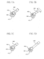
Examples of desirable and undesirable combinations of
necks and stems are shown in Figures 7A-D and Figures 8A-F.
In Figures 7A and 7B, a small stem 412 and a small high angle
neck 420 are shown. The tab 432 on the end of the neck 420
and the slot 430 of the stem 412 are configured so that a
small high angle neck 420 can taper lock with the stem 412 in
only one position. In Figure 7C, the same stem 412 as shown
in Figures 7A-7B together with a small straight neck 520.
The tab 532 of the small straight neck 520 and the slot 430
of the stem 412 are configured so that the tab 532 and the
slot 430 can register, allowing the small straight neck 520
to taper lock with the stem 412 in any position. In Figure
7D, the stem 412 is shown together with a large straight neck
620. The tab 632 on the large straight neck 620 and the slot
430 cannot register, preventing the large straight neck from
taper locking with the stem 412 in any position.
In Figures 8A-F, various neck and stem combinations are
shown. A large stem 512 with a slot 530 is shown in Figures
8A-8B as being able to taper lock with the small high angle
neck 420 in only one angular or circumferential position. In
Figure 8A, the neck 420 is shown as not being able to taper
lock with the stem in a first circumferential position with
respect to the longitudinal axis of the neck 420. In Figure
8B, in which the neck 420 is rotated 180 degrees about its
longitudinal axis with respect to its angular position in
Figure 4A, the neck 420 is shown as being able to taper lock
in the stem 512. In Figures 8C-8D, the large stem 512 is
shown as being able to taper lock with the large high angle
neck 720 in only one position. The tab 732 and slot 530
prevents taper locking of the large high angle neck 720 in
one position. More specifically, in Figure 8C, the large
neck 512 is shown as not being able to taper lock with the
neck 720 in a first angular position. However, in Figure 8D,
when the neck 720 has been rotated about its longitudinal
axis 180 degrees with respect to the position shown in Figure
8C, the neck 720 can taper lock with the stem 512. In Figure
8E, the small straight neck 520 is shown as being able to
taper lock with the large stem 512 in at least one position.
In Figure 8F, the large straight neck 620 is shown as being
able to taper lock with the large stem 512 in at least one
position. It will be appreciated, that the above
combinations are a small sampling of the possible
combinations of necks and stems that are possible.
One or more embodiments of the present invention thus
provides a modular prosthesis 10 kit comprising at least two
differently sized stems, each stem including a tapered bore
having a distal portion and a proximal portion and a neck
registration element on the distal portion of the bore and a
plurality of necks. Each has a tapered distal end and a stem
registration element on the distal end of the neck. The
plurality of necks includes a first neck having a stem
registration element that can register with the neck
registration element of at least one stem in more than one
position, a second neck having a stem registration element
that can register with the neck registration element of at
least one stem in only one position, and a third neck having
a stem registration element that cannot register with at
least one neck in any position.
One or more embodiments of the present invention reduces
the number of parts required to perform a hip or shoulder
prosthesis. A greater number of offset and version options
are provided by the modular prosthesis system of the present
invention compared with prior systems. In addition, it is
possible to provide customized neck versions and offsets.
The modular prosthesis system of the present invention allows
the practitioner to achieve a neck angle that substantially
matches each patient's unique anatomy to allow a greater
range of motion than in prior systems. This ensures minimal
joint reaction force and correct stress transfer from the
upper body to the femur through the ankle in hip systems.
One or more embodiments of the present invention achieves
optimal orientation of the femoral head, resulting in less
stress on the acetabulum, reduced wear, and a reduced chance
of dislocation.
Although the invention herein has been described with
reference to particular embodiments, it is to be understood
that these embodiments are merely illustrative of the
principles and applications of the present invention. For
example, while the embodiments shown in Figures 1-8 show stem
with neck registration elements including slots and necks
with stem registration elements including tabs, this
orientation could be reversed as shown in Figure 9. In
Figure 9, the stem 812 is shown as having a tapered bore 818
and a neck registration element 830 including a shaped tab
extending from the bore. The neck 820 is shown as having a
tapered distal end portion 822 having a bore 832 formed on
the distal end 822 adapted to cooperate with the neck
registration element in the form of a tab 830 to either
permit or prevent registration and taper locking of the stem
812 and the neck 820.
In one or more preferred embodiments of the invention, a
kit or a system may include necks with four different types
of stem registration element configurations and stems with
two different types of neck registration element
configurations, as shown in Figure 10. In Figure 10, the
stem registration elements are shown as tabs and the neck
registration elements are shown as slots. It will be
understood, that this arrangement could be reversed so that
the slots are on the ends of the necks and the tabs are
associated with the stems. Figure 10 is a schematic
representation of such a system. It will be understood, of
course, that the present invention should not be limited to
any particular number of necks, stems, or configurations of
neck registration elements and stem registration elements.
In Figure 10, a first neck N1 has a tab T1, which is a
relatively small tab. The tab T1 is coaxial with and
substantially centrally located on the end of the neck N1, as
indicated by the X and Y axes shown in Figure 10. A second
neck N2 has a tab T2, which is larger than the tab T1. The
tab T2 is coaxial with and substantially centrally located on
the end of the neck N2, as indicated by the X and Y axes
shown in Figure 10. A third neck N3 has a tab T3. The tab
T3 is eccentric with respect to the end of the neck N3, as
noted by the X and Y axes. Tab T3 is larger than tab T1, and
according to one or more embodiments a portion of tab T3 is
elongated in at least one direction along the Y axis. In the
embodiment shown, the tabs T1, T2, and T3 are all
substantially elliptical in cross section. Tab T3 is
elongated along the major axis (the Y axis) of the ellipse.
Neck N4 includes tab T4 eccentric with the end of the neck
N4. Tab T4 is larger than tabs T1, T2, and T3. As shown in
Figure 10, tab T4 is elongated along its major axis (shown as
the Y axis) in one direction.
The kit shown in Figure 10 further includes two stems
having different neck registration element configurations.
Stem S1 includes a slot SL1 that is eccentric to the center
of a bore formed in the stem S1. Slot SL1 is substantially
the same size as the tab T3. Stem S2 includes a slot SL2
that is eccentric to the center of a bore form in the stem
S2. Slot SL2 is substantially the same size as the tab T4.
Slot SL2 is larger in at least one dimension compared to slot
SL1. In the embodiment shown, slot SL2 in longer in one
direction along the major or Y axis of the slot compared to
SL1.
The solid lines terminating in arrows in Figure 10
indicate that a particular neck can taper lock with certain
stems in only one angular position with respect to the
longitudinal axis of the neck. The dashed lines terminating
with an "X" indicate that a particular neck cannot taper lock
with certain stems in any angular position. The double line
terminating with an arrow indicates that particular necks can
taper lock with certain necks in two angular positions with
respect to the longitudinal axis of the neck. Preferably,
the two angular positions are 0 degrees and 180 degrees with
respect to the longitudinal axis of the neck. Thus,
according to the kit or' system shown in Figure 10, the
following neck and stem taper lock combinations are possible
as shown in Table I:
| Angular Position: | Stem Configuration = S1 | Stem Configuration = S2 |
| | 0° | 180° | 0° | 180° |
| Neck N1 | Yes | Yes | Yes | Yes |
| Neck N2 | No | No | Yes | Yes |
| Neck N3 | Yes | No | Yes | No |
| Neck N4 | No | No | Yes | No |
In addition, while the drawings show the stem
registration elements and neck registration elements as being
elliptical in cross section, other configurations or cross-sectional
shapes are within the scope of the invention. Nonlimiting
examples of such shapes are shown in Figure 11 and
include square, triangular, rectangular, polygonal,
hexagonal, octagonal, circular, diamond-shaped, or shaped
like a bow-tie. Furthermore, while the Figures show modular
prostheses the invention is not limited to prostheses. It
will be understood that the term "stem" as used herein may be
part of a prosthetic implant, or it may form part of an
instrument, for example, including but not limited to a rasp,
a broach, or a trial stem. It is therefore to be understood
that numerous modifications may be made to the illustrative
embodiments and that other arrangements may be devised
without departing from the spirit and scope of the present
invention as defined by the appended claims and their
equivalents.