EP1573994B1 - Verfahren und vorrichtung zur übertragung digitaler information mit zeit und frequenz begrenzte funktionen - Google Patents
Verfahren und vorrichtung zur übertragung digitaler information mit zeit und frequenz begrenzte funktionen Download PDFInfo
- Publication number
- EP1573994B1 EP1573994B1 EP03782990A EP03782990A EP1573994B1 EP 1573994 B1 EP1573994 B1 EP 1573994B1 EP 03782990 A EP03782990 A EP 03782990A EP 03782990 A EP03782990 A EP 03782990A EP 1573994 B1 EP1573994 B1 EP 1573994B1
- Authority
- EP
- European Patent Office
- Prior art keywords
- frequency
- time
- bounded
- functions
- bits
- Prior art date
- Legal status (The legal status is an assumption and is not a legal conclusion. Google has not performed a legal analysis and makes no representation as to the accuracy of the status listed.)
- Expired - Lifetime
Links
Images


Classifications
-
- H—ELECTRICITY
- H04—ELECTRIC COMMUNICATION TECHNIQUE
- H04J—MULTIPLEX COMMUNICATION
- H04J1/00—Frequency-division multiplex systems
- H04J1/02—Details
- H04J1/12—Arrangements for reducing cross-talk between channels
-
- H—ELECTRICITY
- H04—ELECTRIC COMMUNICATION TECHNIQUE
- H04J—MULTIPLEX COMMUNICATION
- H04J4/00—Combined time-division and frequency-division multiplex systems
- H04J4/005—Transmultiplexing
-
- H—ELECTRICITY
- H04—ELECTRIC COMMUNICATION TECHNIQUE
- H04L—TRANSMISSION OF DIGITAL INFORMATION, e.g. TELEGRAPHIC COMMUNICATION
- H04L27/00—Modulated-carrier systems
- H04L27/26—Systems using multi-frequency codes
- H04L27/2601—Multicarrier modulation systems
- H04L27/2602—Signal structure
-
- H—ELECTRICITY
- H04—ELECTRIC COMMUNICATION TECHNIQUE
- H04L—TRANSMISSION OF DIGITAL INFORMATION, e.g. TELEGRAPHIC COMMUNICATION
- H04L5/00—Arrangements affording multiple use of the transmission path
- H04L5/02—Channels characterised by the type of signal
- H04L5/06—Channels characterised by the type of signal the signals being represented by different frequencies
Definitions
- This invention relates to digital communications techniques, and more specifically, to systems and methods for increasing the effective data throughput of a transmission medium through the use of Time-and-Frequency Bounded base functions.
- Such a system is described in US 2002/0080889
- POTS plain old telephone service
- Traditional phone service connects remotely-situated telephones to a telephone company central office using twisted pairs of copper wire.
- Traditional phone service was created to enable an exchange of voice information with other phone users using analog signal transmission. More specifically, a POTS telephone set takes an acoustic signal, which is a natural analog signal, and converts it into an electrical equivalent in terms of volume (signal amplitude) and pitch (frequency) for transmission over a copper wire pair.
- Digital Subscriber Line is a communications technique in which the constraint on frequencies is very much relaxed. Typically, frequencies in the range of roughly 25 ... 1100 kHz are used for transmitting data between DSL modems. This allows concurrent use of the wire for data transmission and voice communication. The greater bandwidth available for data communication results in much greater data rates than were previously possible when only the voice channel was available. Note that in contrast with traditional modems, there need to be DSL modems at both ends of the local loop, i.e. one at the subscriber premises, and one in the telephone company central office.
- DSL is used to provide high bandwidth communication links to homes and offices over ordinary telephone lines.
- theoretical DSL bandwidths are high relative to conventional 56K modem technology, one or more practical considerations may significantly limit the actually achieved bandwidth to a much lower number.
- the customer may be able to receive data at rates up to 6.1 megabits per second of a theoretical 8.448 megabits per second, enabling continuous transmission of motion video, audio, and even 3-D effects.
- individual DSL connections will provide from 1.544 Mbps to 512 Kbps downstream and about 128 Kbps upstream.
- the maximum range for DSL without a repeater is 18,000 feet (5.5 kilometers). As distance decreases towards the telephone company central office, the achievable data rate increases. Another factor is the gauge of the copper wire. The heavier 24-gauge wire carries the same data rate farther than 26-gauge wire. Beyond the 5.5-kilometer range, DSL service is possible if the telephone company has extended the central office local loop via one or more fiber optic cables, thus effectively reducing the length of the copper wire in the connection.
- DSL Digital Subscriber Identity
- CAP Carrierless Amplitude Phase Modulation
- a transmission medium connecting a transmitter and receiver of the system is capable of transporting signals, which can be disturbed by the environment, including signals between other pairs of communicating devices (cross talk). There also may be (regulatory) constraints on the power of the signal inserted in the transmission medium.
- the transmitter generates a signal, driving the transmission line with a signal equivalent to an encoded input sequence.
- the receiver receives the signal and converts that signal into an output sequence, which is a copy of the input sequence if no errors occur.
- the transmitter and receiver devices combined allow for calibration, providing a means for the devices together to compensate for certain types of distortion occurring in the transmission medium.
- the system must also ensure that the receiver can generate a local clock, appropriate for the reception and conversion of the transmitted signal into the output sequence.
- a primary object of the invention is to provide techniques for increasing the effective digital data throughput of a communications link which may include any of a wired transmission medium, a wireless transmission link, a satellite link, and possibly a fiber optic communication network.
- an object of this invention is to provide systems and methods in which the effective capacity of a communications link is enhanced.
- a further object of the invention is to provide systems and methods which are more robust against interference on the communications link than current systems and methods.
- TFB Time-and-Frequency-Bounded
- the width of a frequency band they occupy can be set by scaling their time variables. In this manner a variable number of frequency bands of arbitrary widths can be employed. Optimizing the TFB waveforms for occupying relatively narrow frequency bands, by scaling their time variables accordingly, allows more efficient use of available bandwidth and the effect of an RF interference source is limited to the small frequency band of the interference source, having little effect on the communications link as a whole.
- TFB functions are orthogonal TFB functions. From this sub-class, Hermite-Gauss functions are a preferred embodiment. It is noted that a system using Hermite-Gauss functions per se is known from United States patent US 3,384,715.
- the incoming bits comprise the digital bit stream (input sequence) carried on one or more incoming channels in the form of binary "on" and "off" bits.
- data is encoded by mapping bits from a representation of the data to at least approximations of the base functions.
- the input sequence is encoded in blocks. In the remainder these will be referred to as TFB blocks.
- the TFB blocks are constructed from N different base functions, N being the number of functions used for encoding (as used herein, N is a positive integer).
- this mapping process is implemented by mapping a first incoming bit to a first TFB function, a second incoming bit to a second TFB function, and so on, until an N th TFB function is reached, whereupon the process cycles back to the first TFB function.
- mapping of one bit to one TFB function is descriptive only, and that in practice multiple bits may be mapped onto a single TFB function.
- the incoming stream of bits is buffered prior to encoding.
- the bits are grouped in groups of length M, where M depends on the number of bits needed for error correction; N-M bits are added for this error correction.
- M depends on the number of bits needed for error correction
- N-M bits are added for this error correction.
- the first M bits of the not yet encoded input sequence, and N-M error correction bits, are then mapped onto N different base functions. Note that both M and N may be defined dynamically, possibly per block. This encoding can be repeated indefinitely. In case there are insufficient data in the input sequence to fill the block, padding bits are generated preferably.
- the weighing factors are by no means limited to -1 and +1 and can be chosen freely to suit application or system requirements.
- Each respective weighed TFB function constitutes a component of the TFB waveform that is to be transmitted.
- Each of respective weighed TFB functions possesses a corresponding set of frequency components and lasts for a corresponding length of time.
- the predetermined TFB functions could all specify substantially the same length of time, but this is not a requirement.
- a first predetermined TFB function could be utilized that has a different time duration than a second predetermined TFB function.
- a set of TFB functions could be selected which fit within a predetermined frequency range.
- the time durations of "interesting" (non-zero) parts of the functions will differ from function to function.
- centers of the interesting parts of the functions can be made to substantially coincide in time for all functions in the set of TFB functions.
- the TFB blocks are transformed into TFB packets by modulating the block waveform with e.g. a central frequency of the channel to be used for the transmission of this group of bits and subsequently generating a waveform corresponding to a modulated function. Additional to or instead of modulation, processing may be added to compensate, either fully or in part, for the effect of the transmission medium. TFB blocks may also be transformed into TFB packets without applying additional signal processing to the blocks.
- the resulting packets are transmitted over a physical transmission medium.
- the packets are preferably transmitted in the order in which the parent blocks were constructed.
- the transmitted packets are temporally spaced. Packets may be sent in a non-continuous stream. A waveform corresponding to the packet sequence is generated and physically realized on the transmission medium
- the waveform as realized in a transmitter and distorted while propagated over the transmission medium, is retrieved from the transmission medium by a receiver.
- a distorted waveform is processed for compensation of the effect of the transmission medium on the waveform and/or demodulation with a carrier frequency and/or filtering, e.g. for limiting a frequency range of the signal, resulting in a sequence of noisy packets.
- Compensation for a distortion introduced by the transmission medium can be incorporated in the base functions; in such a case a collection of base functions may vary, possibly per block. Compensation for cross talk induced during transmission may be included in processing in both the transmitter and the receiver.
- receiving devices and methods are disclosed for receiving, detecting, and decoding an incoming TFB composite information stream. Both encoding and decoding may contain mechanisms for error correction.
- the TFB functions may be detected by the receiver based upon frequency domain characteristics, time domain characteristics, or both.
- the receiver transforms a signal received on the transmission medium connecting the receiver with the transmitter into the bit sequence that was used by that transmitter for generating the received signal.
- This process preferably involves converting an analog signal into a sampled stream of bits.
- the, digitally encoded, signal is demodulated.
- the sampled signal can be matched with a set of TFB functions in order to determine the weighing factor for each of the functions in the set. This results in bit i being set to 0 if that factor is e.g. -1, or to 1 if the factor is e.g. +1 (other weighing factors and protocols are of course possible and lie within the scope of the invention).
- an i th function maps onto an i th bit in the sequence generated for a single packet.
- determining the weighing factors provides information on noise generated in the communication link, which is then estimated and sent back to the transmitter for adaptation of the encoding, if necessary
- decoding information is extracted and the noisy packets are decoded using at least approximations of N TFB functions.
- functions used for decoding may be different from functions used for encoding.
- noisy packets are decomposed into N weights, one for each of the base functions used for decoding.
- the resulting N weighing factors are mapped onto N bits in such a way that the input sequence is reconstructed with the probability P as described above.
- the extracted bits are processed with an error correction algorithm matching the algorithm used for encoding so that the original input bit sequence results.
- the resulting bits are made available as output sequence.
- the output bit sequence is placed in a buffer and made available for external equipment, such as a computer.
- each of the steps involved in processing of the received signal may be carried out in an analog and/or digital fashion.
- the functions used for decoding may be digitized before application in decoding of the received signal.
- This invention can be used to increase bandwidth capacity on existing transmission media and/or in conjunction with satellite transmission protocols.
- This invention has the following advantages:
- the aforementioned techniques can be applied not only to the communication of digital information, but also e.g. to its storage in which one or more digital information streams are stored on a storage medium based on analog techniques.
- the systems and methods of the present invention enhance effective capacity of communications links or storage media by transmitting a plurality of TFB waveform components each characterized by a unique TFB function.
- a combination of TFB functions is used to construct a TFB packet, and a plurality of TFB packets is used to generate a TFB stream.
- incoming information is received as a bit stream of binary coded information ("0"s and "1”s),and then transformed to an equivalent coding in which the binary "0" and "1" of the bit stream, are translated into equivalent weighing factors to be applied to a TFB function selected from a set of predetermined TFB functions as described below.
- a TFB function selected from a set of predetermined TFB functions as described below.
- the TFB packet is constructed from a set of TFB functions. These functions are utilized, potentially in a modified form, to encode a sequence of bits as a continuous-time signal, and to decode this signal into the sequence of bits that it represents. Encoding occurs by computing a weighted sum, also called a linear combination, of the TFB functions. The weight for a given TFB function is given by the weighing factor for a bit or group of bits mapped onto that function.
- TFB functions have the advantageous property of being substantially confined in both of the frequency and the time domain.
- a preferred sub-class of TFB functions are orthogonal TFB functions. Each TFB waveform component in the predetermined set of orthogonal TFB waveform components is unique and mutually orthogonal with respect to all other TFB waveform components in this set.
- a more preferred sub-class of the orthogonal TFB functions are Hermite-Gaussian functions.
- a Hermite-Gaussian function is a function that has the same shape (modulo a constant) in both the frequency domain and the time domain.
- the invention comprises the use of both Hermite-Gaussian functions and other TFB functions.
- TFB functions are summed, after the weighting process described above, thereby providing TFB blocks and, thence, a stream of TFB blocks.
- Methods and systems in accordance with the invention may be used in conjunction with any transmission medium capable of conveying or transmitting a stream of information.
- Such transmission media may include wire, satellite transmission, wireless communications, radio frequency transmission over the air, radio frequency transmission through a coaxial cable, fiber optics, etc. and such protocols as T-1, ATM, Frame Relay, etc.
- Systems and methods developed in accordance with the invention will function with virtually any digital information capable of being transmitted or stored using analog technology, such as data, image, video or voice applications.
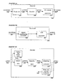
- Fig. 1A is a block diagram setting forth an illustrative implementation of a transmitter 100 of a system according to the present invention equipped to convert incoming binary data into a TFB stream for transmission over a transmission medium to a receiver.
- An incoming binary data bit stream 110 includes a sequence of logical "1"s and "0"s. This bit stream 110 may originate from, for example, but not limited to, a computing device such as a personal computer, server, or computer-readable data storage device, and/or from a telephonic or other communications device.
- the incoming bit stream 110 is converted into TFB blocks 130 by an encoder 120, which will be described in more detail hereinafter with respect to Fig. 1B.
- the TFB blocks 130 are transformed into TFB packets 150 by modulating the block waveform with e.g. the central frequency of the channel to be used for transmission of this group of bits by a modulator 140. Additional to or instead of modulation processing may be added to compensate, either fully or in part, for the effect of the transmission medium. In an alternative embodiment TFB blocks 130 may also be transformed into TFB packets 150 without applying additional signal processing to the blocks 130. Subsequently a waveform 170 corresponding to the TFB packet 150 is generated by a waveform generator 160 and physically realized on the transmission medium. The waveform generator 160 will be described in more detail hereinbelow with respect to Fig. 1C.
- Fig. 1B is a block diagram representing an illustrative implementation of the encoder 120 of the transmitter 100 shown in Fig. 1A.
- the incoming bit stream 110 may be buffered in a receiving mechanism 121 before being encoded.
- the incoming bits are grouped in groups 122 of length M.
- An error correction mechanism 123 may add N-M bits for error correction, thus obtaining a group 124 of length N containing M bits of data and N-M error correction bits.
- Group length N corresponds to the number of TFB functions used for encoding and on the number of bits mapped onto a single TFB function. Both M and N may be determined dynamically, possibly per block.
- the error correction mechanism may be arranged to receive information on the quality of the transmission and/or the transmission medium on an input 129 to optimize the error correction algorithm depending on effects of the transmission and/or the transmission medium.
- padding bits may be added to the group 122 or 124.
- a weighing mechanism 125 for each bit in the group 124 a weighing factor is determined, which is to reflect the value of the bit ("0" or "1"). As an example, the weighing factor is -1 if the bit value is 0, and +1 if the bit value is 1.
- the weighing mechanism may be arranged to receive information on the quality of the transmission and/or the transmission medium on an input 131 for optimizing the weight generation, given the conditions of the transmission and/or the transmission medium.
- the weighing factors are by no means limited to the example given above and can be chosen freely to suit the application or system needs.
- a mapping mechanism 127 maps the N bits of the group 124 of bits onto N TFB functions, generated by a signal generation mechanism 128.
- the signal generation mechanism 128 may be arranged to receive information on the quality of the transmission and/or the transmission medium for optimizing the TFB functions, given the conditions of the transmission and/or the transmission medium
- the TFB functions are digital representations of TFB functions. It is, however, also possible to use analog, physical representations of the TFB functions.
- This mapping is achieved by multiplying a first function from a selected set of TFB functions with a first weighing factor, a second function with a second weighing factor and so on until all N functions have been multiplied with a weighing factor.
- the first function is multiplied by a weighing factor corresponding to the first bit of the group 124, the second function with a weighing factor corresponding to the second bit of the group 124 and so on.
- the mapping mechanism 125 adds all N thus weighted functions to form a TFB block 130.
- a weighing factor is determined, which is to reflect the value of the set of bits.
- the mapping mechanism 127 maps the N bits of the group 124 of bits onto N T TFB functions, generated by the signal generation mechanism 128. This mapping is, again, achieved by multiplying the first function from the selected set of TFB functions with the first weighing factor, the second function with the second weighing factor and so on until all N T functions have been multiplied with a weighing factor.
- the first function is multiplied by a weighing factor corresponding to the first set of n bits of the group 124, the second function with a weighing factor corresponding to the second set of n bits of the group 124 and so on.
- the mapping mechanism 125 adds all N T thus weighted functions to form a TFB block 130.
- Fig. 1C is a block diagram representing an illustrative implementation of the waveform generator 160 of the transmitter 100 shown in Fig. 1A.
- a sampler 162 is used to determine a digital representation 164 of the waveform of the packet 150 as generated by the modulator 140.
- a Digital-to-Analog (D/A) converter 166 converts the digital waveform 164 into an analog waveform.
- a transmission mechanism 168 puts the analog TFB waveform 170 on the transmission medium.
- the incoming bits 110 are digitally mapped on digital representations of the N TFB functions, the sum of which (block 130) is digitally determined and modulated before being converted to an analog waveform 170 which is put on the transmission medium.
- the invention is by no means limited to this embodiment.
- Alternative embodiments, wherein the incoming bit stream 110 is converted to an analog signal at a different point within the system all fall within the scope of the invention. Examples are multiplying N analog TFB functions with analog equivalents of the weighing factors or converting the N digitally weighed functions to analog waveforms prior to adding the separate waveforms to form a block.
- the invention could be embodied electronically, in firmware, in software, in hardware or in various combinations thereof.
- Fig. 2A is a block diagram setting forth an illustrative implementation of a receiver 200 of the system according to the present invention equipped to decode an incoming TFB waveform 210 into one or more streams of binary data 280.
- a front end 220 of the receiver 200 receives waveforms 210 from the transmission medium. As described hereinafter in more detail with respect to Fig. 2A the front end 220 converts the received waveform 210 to a sampled packet 230.
- a decoder 240 decomposes the packet 230 into a group 260 of bits as described below with respect to Fig. 2C. Finally the bit groups 260 are restored to a bit stream 280 by a bit stream generator 270 as described in more detail hereinbelow with respect to Fig. 2D.
- Fig. 2B is a block diagram representing an illustrative implementation of the front end 220 of the receiver 200 shown in Fig. 2A.
- the front end 220 receives an analog waveform signal 210 from the transmission medium, e.g. a wire.
- the incoming signal may be conditioned to improve the amplitude and/or signal to noise ratio in a signal conditioning mechanism 222.
- An Analog-to-Digital (A/D) converter 224 generates a digital sampled packet 230 corresponding to the received analog waveform 210.
- A/D Analog-to-Digital
- Fig. 2C is a block diagram representing an illustrative implementation of the decoder 240 of the receiver 200 shown in Fig. 2A.
- a waveform 170 as realized in the transmitter, may be distorted while propagated over the transmission medium, the distorted waveform 210 may be processed for compensation of the effect of the transmission and/ or the transmission medium, e.g. noise, attenuation and phase shifts, on the waveform by a compensator mechanism 246 yielding compensated received packets 248.
- compensation for the distortion introduced by the transmission medium can also be incorporated in the base functions; in such a case the collection of base functions may vary, possibly per block.
- Illustratively compensation for cross talk induced during transmission may be included in processing in both the transmitter 100 and the receiver 200.
- a calibration mechanism 242 may be used to determine the parameters that govern the compensation by comparing the received waveform 210 with a known sent waveform.
- a demodulator 250 demodulates the (digitally encoded) packets 248 with a carrier frequency for each channel used in the transmission, resulting in sampled blocks 252.
- sampled blocks 252 are matched with a set of TFB functions in order to determine a weighing factor for each of the functions in the set.
- bit i being set to 0 if that weighing factor is -1, or to 1 if the weighing factor is +1, in the case of the weighing factors given in the example above.
- the weighing factors are by no means limited to the example and can be chosen freely to suit the application or system needs.
- an i th function maps onto an i th bit in the sequence generated for a single block 252.
- the resulting N weighing factors are mapped onto a group 260 of N bits in such a way that the input block 124 is reconstructed with the probability P.
- the matching is done by computing an approximation of the inner products of the received packets 248 with the TFB functions used to decode the data.
- the matching process provides information on noise generated in the transmission and/or transmission medium, which is then estimated by a noise estimation mechanism 256 and sent back 258 to the transmitter for adaptation of the encoding, if required.
- this information can, for example, be directed to the input 129 of the error correction mechanism for optimizing the error correction algorithm, and/or to the input 131 of the weighing mechanism to be used in optimizing the weights applied to the TFB functions, given the effects of the transmission medium.
- the information can also be used to modify the set of TFB functions used within the transmitter. It is also possible to use information that has not been estimated by the estimation mechanism 256, e.g. from a separate measurement, for optimization.
- Fig. 2D is a block diagram representing an illustrative implementation of the bit stream generator 270 of the receiver 200 shown in Fig. 2A.
- the M data bits in the groups 260 extracted in the matching mechanism 254 are processed with an error correction algorithm, in an error correction mechanism 272, matching an algorithm used for encoding, so that the original bit sequence results.
- Group 274 of M decoded bits is placed in a buffer 276 and, after being concatenated, the resulting bit stream 280 is made available for external equipment, such as a computer, by an interface mechanism 278.
- the incoming waveforms 210 are digitized after signal conditioning and before compensation.
- the invention is by no means limited to this embodiment.
- Alternative embodiments, wherein the incoming waveform 210 is converted to digital data at a different point within the system all fall within the scope of the invention. Examples are digitally applying signal conditioning or compensating for e.g. attenuation in an analog fashion.
- the invention could be embodied electronically, in firmware, in software, in hardware or in various combinations thereof.
- Figs. 1A and 2A may be employed to create multiple channels using frequency division multiplexing (FDM) where each of the channels consists of a stream of packets. Each of these packets, in turn, is constructed from weighted sums of a set of TFB functions.
- FDM frequency division multiplexing
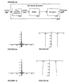
- Fig 3B is an example of a non-TFB function, in the frequency domain.
- the function of Fig. 3B is nicely confined to a rectangular slice in the frequency domain of 1 Hz wide, but its Fourier transform, the Sinc function, spills into plus and minus infinity in the time domain (Fig. 3A).
- a function that is confined to a rectangular slice in the time domain spills into plus and minus infinity in the frequency domain.
- Fig. 4A is an example of a TFB function in the time domain
- Fig 4B the corresponding TFB function in the frequency domain.
- Figs. 5A and 5B show enlargements of the time domain graphs of the TFB function, and the Sinc function, respectively. Note that the vertical plot range is reduced with respect to Figs. 3A and 4A in order to show the decay of local maxima.
Landscapes
- Signal Processing (AREA)
- Engineering & Computer Science (AREA)
- Computer Networks & Wireless Communication (AREA)
- Mobile Radio Communication Systems (AREA)
- Circuits Of Receivers In General (AREA)
- Data Exchanges In Wide-Area Networks (AREA)
- Digital Transmission Methods That Use Modulated Carrier Waves (AREA)
- Selective Calling Equipment (AREA)
- Arrangements For Transmission Of Measured Signals (AREA)
- Communication Control (AREA)
- Detection And Prevention Of Errors In Transmission (AREA)
- Cable Transmission Systems, Equalization Of Radio And Reduction Of Echo (AREA)
- Compression, Expansion, Code Conversion, And Decoders (AREA)
Claims (31)
- System zum Erhöhen eines Durchsatzes digitaler Daten durch Übertragen von zeit- und frequenzbegrenzten Funktionspaketen über ein Übertragungsmedium, wobei die zeit- und frequenzbegrenzten Funktionen glatte Funktionen sind, welche sowohl im Zeitbereich-als auch im Frequenzbereich eine begrenzte Ausdehnung haben, außerhalb welcher die Amplitude des Produkts der Funktion mit einem Polynom vernachlässigbar oder zumindest niedriger als ein vorbestimmter Schwellenwert ist, wobei das System einen Sender aufweist, mit:einem digitalen Empfangsmechanismus 121 zum Empfangen eines eingehenden Stroms 110 von digitalen Informationen auf einer oder mehreren eingehenden digitalen Leitungen, wobei die digitalen Informationen in einen binären Bitformat aus "0" und "1" vorliegen,einem Gewichtungsmechanismus 125 zum Erzeugen entsprechender Gewichtungsfaktoren unter Verwendung der digitalen Informationen, die von dem digitalen Empfangsmechanismus 121 empfangen werden;einem Signalerzeugungsmechanismus 128, der ausgestattet ist, um eine Vielzahl von zeit- und frequenzbegrenzten Funktionen zu erzeugen;
gekennzeichnet durcheinen Abbildungsmechanismus 127, der mit dem Signalerzeugungsmechanismus gekoppelt ist, zum Anwenden von durch den Gewichtungsmechanismus 128 erzeugten und empfangenen Gewichtungsfaktoren auf eine entsprechend erzeugte zeit- und frequenzbegrenzte Funktion, und danach Summieren der gewichteten zeit- und frequenzbegrenzten Funktionen, um dadurch eine entsprechende Vielzahl von zeit- und frequenzbegrenzten Paketen 150 zu erzeugen, wobei die Vielzahl von zeit- und frequenzbegrenzten Paketen einen zeit- und frequenzbegrenzten Informationsstrom aufweisen; undeinen Übertragungsmechanismus 168 zum Übertragen der Vielzahl von zeit- und frequenzbegrenzten Paketen über das Übertragungsmedium. - System gemäß Anspruch 1, wobei der Empfangsmechanismus 121-eine Einrichtung zum Puffern des eingehenden Stroms und eine Einrichtung zum Gruppieren der Bits in Gruppen aufweist.
- System gemäß Anspruch 2, wobei das System eingerichtet ist, um die Anzahl von Bits in einer Gruppe dynamisch zu bestimmen.
- System gemäß Anspruch 2, wobei die Einrichtung zum Gruppieren der Bits eingerichtet ist, um im Fall, dass in dem eingehenden Strom von Informationen unzureichende Daten sind, eines oder mehrere Füllbits hinzuzufügen, um eine Gruppe aufzufüllen.
- System gemäß Anspruch 2, mit einem Fehlerkorrekturmechanismus 129, der eingerichtet ist, um Fehlerkorrekturbits zu den Bitgruppen hinzuzufügen.
- System gemäß Anspruch 5, wobei das System eingerichtet ist, um die Anzahl von Fehlerkorrekturbits dynamisch zu definieren.
- System gemäß Anspruch 1, mit einem Modulator zum Modulieren der Summe der gewichteten zeit- und frequenzbegrenzten Funktionen mit einer Trägerfrequenz.
- System gemäß Anspruch 5, wobei der Fehlerkorrekturmechanismus 129 eingerichtet ist, um Informationen über die Qualität der Übertragung und/oder des Übertragungsmediums bei einer Eingabe zu empfangen, um den Fehlerkorrekturalgorithmus in Abhängigkeit von Einflüssen des Übertragungsmediums zu optimieren.
- System gemäß Anspruch 1, wobei der Gewichtungsmechanismus 125 eingerichtet ist, um Informationen über die Qualität der Übertragung und/oder des Übertragungsmediums bei einer Eingabe zu empfangen, zum Optimieren einer Gewichtungserzeugung in Anbetracht der Zustände des Übertragungsmediums.
- System gemäß Anspruch 1, wobei der Signalerzeugungsmechanismus 160 ausgestattet ist, um eine Vielzahl von digitalen Darstellungen von zeit- und frequenzbegrenzten Funktionen zu erzeugen.
- System gemäß Anspruch 1, weiter mit einem Empfänger 200 zum Empfangen eines eingehenden Informationsstroms 210 in der Form von zeit- und frequenzbegrenzten Paketen, die auf dem Übertragungsmedium übertragen werden; wobei der Empfänger einen Vorderabschnitt 220, einen Decodierer 240 zum Extrahieren der digitalen Informationen und einen Erzeugungsmechanismus 270 zum Erzeugen eines oder mehrerer abgehender binärer Datenbitströme 280 aufweist.
- System gemäß Anspruch 11, wobei der Vorderabschnitt 220 einen Analog-Digital-Wandler 224 zum Umwandeln des eingehenden Informationsstroms in einen abgetasteten Strom von Bits 230 aufweist.
- System gemäß Anspruch 11, wobei der Decodierer einen Kompensator 246 zum Korrigieren des abgetasteten eingehenden Informationsstroms 230 bezüglich Verzerrungen des Signals während der Übertragung und zum Bestimmen der Parameter, die die Korrektur steuern, aufweist.
- System gemäß Anspruch 13, wobei der Fehlerkorrekturmechanismus des Senders 129 eingerichtet ist, um die Parameter vom Kompensator des Empfängers zu empfangen.
- System gemäß Anspruch 13, wobei der Gewichtungsmechanismus 125 des Senders eingerichtet ist, um die Parameter vom Kompensator des Empfängers zu empfangen.
- System gemäß Anspruch 11, wobei der Decodierer 240 einen Demodulator 250 zum Demodulieren der zeit- und frequenzbegrenzten Pakete aufweist.
- System gemäß Anspruch 11, wobei der Decodierer 240 einen Signalerzeugungsmechanismus aufweist, der ausgestattet ist, um eine Vielzahl von zeit- und frequenzbegrenzten Funktionen zu erzeugen.
- System gemäß Anspruch 17, wobei der Decodierer einen Anpassungsmechanismus 254 zum Anpassen des empfangenen Informationsstroms an den Satz von zeit- und frequenzbegrenzten Funktionen aufweist, um für jede Funktion in dem Satz den Gewichtungsfaktor zu bestimmen.
- System gemäß Anspruch 18, wobei die zeit- und frequenzbegrenzten Funktionen, die in dem Anpassungsmechanismus verwendet werden, von den zeit- und frequenzbegrenzten Funktionen, die in dem Abbildungsmechanismus verwendet werden, verschieden sind.
- System gemäß Anspruch 11, wobei der Decodierer einen Schätzmechanismus 256 zum Schätzen von Informationen über das Rauschen, das durch das und/oder in dem Übertragungsmedium erzeugt wird, aufweist.
- System gemäß Anspruch 20, wobei der Signalerzeugungsmechanismus des Empfängers 200 eingerichtet ist, um die Informationen des Schätzmechanismus 256 zu empfangen und zu verwenden, um die erzeugten zeit- und frequenzbegrenzten Funktionen abzugleichen.
- System gemäß Anspruch 20, wobei der Signalerzeugungsmechanismus 128 des Senders 100 eingerichtet ist, um die Informationen des Schätzmechanismus 256 zu empfangen und zu verwenden, um die erzeugten zeit- und frequenzbegrenzten Funktionen abzugleichen.
- System gemäß Anspruch 11, wobei der Erzeugungsmechanismus 270 einen Fehlerkorrekturmechanismus 272 zum Anwenden einer Fehlerkorrektur auf den einen oder die mehreren abgehenden Datenströme aufweist.
- System gemäß Anspruch 11, wobei der Erzeugungsmechanismus 270 einen Puffer 76 für die decodierten Bits aufweist.
- System gemäß Anspruch 11, wobei der Erzeugungsmechanismus 270 einen Mechanismus 178 zum Verknüpfen der Bits und/oder zum Verfügbarmachen der Bits für ein externes Gerät aufweist.
- System gemäß Anspruch 11, wobei zumindest ein Teil des Decodierers in Software implementiert ist, die in einem programmierbaren Berechnungsmechanismus ausgeführt wird, wie etwa einem Allzweckcomputer, einem digitalen Signalprozessor (DSP) oder einem FPGA.
- System gemäß Anspruch 1 oder 11, wobei zumindest eine der zeit- und frequenzbegrenzten Funktionen aus der Teil-Klasse von orthogonalen zeit- und frequenzbegrenzten Funktionen ausgewählt wird.
- System gemäß Anspruch 1 oder 11, wobei zumindest eine der zeit- und frequenzbegrenzten Funktionen aus der Teil-Klasse von Hermite-Gauss-Funktionen ausgewählt wird.
- Sender, mit:einem digitalen Empfangsmechanismus zum Empfangen eines eingehenden Stroms von digitalen Informationen auf einer oder mehreren eingehenden digitalen Leitungen, wobei die digitalen Informationen in einen binären Bitformat aus "0" und "1" vorliegen,einem Gewichtungsmechanismus zum Erzeugen entsprechender Gewichtungsfaktoren unter Verwendung der digitalen Informationen, die von dem digitalen Empfangsmechanismus empfangen werden;einem Signalerzeugungsmechanismus, der ausgestattet ist, um eine Vielzahl von zeit- und frequenzbegrenzten Funktionen zu erzeugen;einem Abbildungsmechanismus, der mit dem Signalerzeugungsmechanismus gekoppelt ist, zum Anwenden von durch den Gewichtungsmechanismus erzeugten und empfangenen Gewichtungsfaktoren auf eine entsprechend erzeugte zeit- und frequenzbegrenzte Funktion, und danach Summieren der gewichteten zeit- und frequenzbegrenzten Funktionen, um dadurch eine entsprechende Vielzahl von zeit- und frequenzbegrenzten Paketen zu erzeugen, wobei die Vielzahl von zeit- und frequenzbegrenzten Paketen einen zeit- und frequenzbegrenzten Informationsstrom aufweisen; undeinem Übertragungsmechanismus zum Übertragen der Vielzahl von zeit- und frequenzbegrenzten Paketen über das Übertragungsmedium.
- Empfänger zum Empfangen eines eingehenden Informationsstroms in der Form von zeit- und frequenzbegrenzten Paketen, die auf einem Übertragungsmedium übertragen werden; wobei der Empfänger aufweist einen Vorderabschnitt, einen Decodierer zum Extrahieren der digitalen Informationen, wobei der Decodierer einen Demodulator zum Demodulieren der zeit- und frequenzbegrenzten Pakete aufweist; und einen Anpassungsmechanismus zum Anpassen des empfangenen Informationsstroms an einen Satz von zeit- und frequenzbegrenzten Funktionen, um für jede Funktion in dem Satz einen Gewichtungsfaktor zu bestimmen, und Abbilden der Gewichtungsfaktoren auf Gruppen von Bits; und einen Erzeugungsmechanismus, der die Gruppen von Bits verarbeitet, um einen oder mehrere abgehende binäre Datenbitströme zu erzeugen.
- Verfahren zum effektiven Erhöhen eines Durchsatzes digitaler Daten durch Übertragen von zeit- und frequenzbegrenzten Funktionspaketen über ein Übertragungsmedium, wobei die zeit- und frequenzbegrenzten Funktionen glatte Funktionen sind, welche sowohl im Zeitbereich als auch im Frequenzbereich eine begrenzte Ausdehnung haben, außerhalb welcher die Amplitude des Produkts der Funktion mit einem Polynom vernachlässigbar oder zumindest niedriger als ein vorbestimmter Schwellenwert ist, wobei das Verfahren die Schritte aufweist:Empfangen eines eingehenden Stroms von digitalen Informationen in einen binären Bitformat aus "0" und "1",Verwenden der digitalen Informationen, um eine Sequenz von Gewichtungsfaktoren zu erzeugen;Erzeugen eine Vielzahl von zeit- und frequenzbegrenzten Funktionen;Anwenden der Gewichtungsfaktoren auf die Vielzahl von zeit- und frequenzbegrenzten Funktionen, undSummieren der gewichteten zeit- und frequenzbegrenzten Funktionen, um dadurch eine entsprechende Vielzahl von zeit-- und frequenzbegrenzten Paketen zu erzeugen, wobei eine Vielzahl von zeit- und frequenzbegrenzten Paketen einen zeit- und frequenzbegrenzten Informationsstrom aufweisen; undÜbertragen der Vielzahl von zeit- und frequenzbegrenzten Paketen über das Übertragungsmedium.
Applications Claiming Priority (3)
| Application Number | Priority Date | Filing Date | Title |
|---|---|---|---|
| US326318 | 2002-12-20 | ||
| US10/326,318 US6898207B2 (en) | 1997-10-08 | 2002-12-20 | Techniques for communicating information using Hermite-Gaussian basis functions |
| PCT/NL2003/000911 WO2004057821A2 (en) | 2002-12-20 | 2003-12-19 | System and method for communicating digital information using time-and-frequency-bounded base functions |
Publications (2)
| Publication Number | Publication Date |
|---|---|
| EP1573994A2 EP1573994A2 (de) | 2005-09-14 |
| EP1573994B1 true EP1573994B1 (de) | 2007-06-06 |
Family
ID=32680739
Family Applications (1)
| Application Number | Title | Priority Date | Filing Date |
|---|---|---|---|
| EP03782990A Expired - Lifetime EP1573994B1 (de) | 2002-12-20 | 2003-12-19 | Verfahren und vorrichtung zur übertragung digitaler information mit zeit und frequenz begrenzte funktionen |
Country Status (12)
| Country | Link |
|---|---|
| US (1) | US6898207B2 (de) |
| EP (1) | EP1573994B1 (de) |
| KR (1) | KR101098634B1 (de) |
| CN (1) | CN1830188B (de) |
| AT (1) | ATE364283T1 (de) |
| AU (1) | AU2003290454A1 (de) |
| CA (1) | CA2511014C (de) |
| DE (1) | DE60314286T2 (de) |
| DK (1) | DK1573994T3 (de) |
| ES (1) | ES2287547T3 (de) |
| PT (1) | PT1573994E (de) |
| WO (1) | WO2004057821A2 (de) |
Families Citing this family (7)
| Publication number | Priority date | Publication date | Assignee | Title |
|---|---|---|---|---|
| US6944118B2 (en) * | 1997-10-08 | 2005-09-13 | Bandwidth Technology Corp. | System and method for communicating digital information using time-and-frequency-bounded base functions |
| US11044043B2 (en) | 1997-10-08 | 2021-06-22 | Erik Borculo | System and method for communicating information using time-and-frequency-bounded base functions |
| FI112427B (fi) * | 1999-11-05 | 2003-11-28 | Nokia Corp | Menetelmä langattoman päätelaitteen ominaisuuksien määrittämiseksi multimediasanoman välityspalvelussa, multimediasanoman välityspalvelu ja multimediapäätelaite |
| FI112307B (fi) | 2000-08-02 | 2003-11-14 | Nokia Corp | Viestintäpalvelu |
| US9002286B2 (en) * | 2009-03-30 | 2015-04-07 | Massachusetts Institute Of Technology | Method and system for identification and mitigation of errors in non-line-of-sight distance estimation |
| US9413448B2 (en) * | 2014-08-08 | 2016-08-09 | Nxgen Partners Ip, Llc | Systems and methods for focusing beams with mode division multiplexing |
| US10326526B2 (en) * | 2016-09-08 | 2019-06-18 | Nxgen Partners Ip, Llc | Method for muxing orthogonal modes using modal correlation matrices |
Family Cites Families (6)
| Publication number | Priority date | Publication date | Assignee | Title |
|---|---|---|---|---|
| US3384715A (en) * | 1964-09-17 | 1968-05-21 | Mc Donnell Douglas Corp | Multiplex communication systems employing orthogonal hermite waveforms |
| US4783804A (en) * | 1985-03-21 | 1988-11-08 | American Telephone And Telegraph Company, At&T Bell Laboratories | Hidden Markov model speech recognition arrangement |
| US5285474A (en) * | 1992-06-12 | 1994-02-08 | The Board Of Trustees Of The Leland Stanford, Junior University | Method for equalizing a multicarrier signal in a multicarrier communication system |
| US5715367A (en) * | 1995-01-23 | 1998-02-03 | Dragon Systems, Inc. | Apparatuses and methods for developing and using models for speech recognition |
| US6317161B1 (en) * | 1997-07-31 | 2001-11-13 | Texas Instruments Incorporated | Horizontal phase-locked loop for video decoder |
| US6603818B1 (en) * | 1999-09-23 | 2003-08-05 | Lockheed Martin Energy Research Corporation | Pulse transmission transceiver architecture for low power communications |
-
2002
- 2002-12-20 US US10/326,318 patent/US6898207B2/en not_active Expired - Lifetime
-
2003
- 2003-12-12 CN CN200380106891.9A patent/CN1830188B/zh not_active Expired - Fee Related
- 2003-12-19 EP EP03782990A patent/EP1573994B1/de not_active Expired - Lifetime
- 2003-12-19 ES ES03782990T patent/ES2287547T3/es not_active Expired - Lifetime
- 2003-12-19 CA CA2511014A patent/CA2511014C/en not_active Expired - Fee Related
- 2003-12-19 PT PT03782990T patent/PT1573994E/pt unknown
- 2003-12-19 DK DK03782990T patent/DK1573994T3/da active
- 2003-12-19 AT AT03782990T patent/ATE364283T1/de active
- 2003-12-19 AU AU2003290454A patent/AU2003290454A1/en not_active Abandoned
- 2003-12-19 WO PCT/NL2003/000911 patent/WO2004057821A2/en not_active Ceased
- 2003-12-19 DE DE60314286T patent/DE60314286T2/de not_active Expired - Lifetime
- 2003-12-19 KR KR1020057011607A patent/KR101098634B1/ko not_active Expired - Fee Related
Also Published As
| Publication number | Publication date |
|---|---|
| CN1830188B (zh) | 2011-04-06 |
| AU2003290454A8 (en) | 2004-07-14 |
| CN1830188A (zh) | 2006-09-06 |
| CA2511014C (en) | 2012-10-30 |
| ATE364283T1 (de) | 2007-06-15 |
| DE60314286T2 (de) | 2008-02-07 |
| KR101098634B1 (ko) | 2011-12-23 |
| HK1076949A1 (en) | 2006-01-27 |
| KR20060093644A (ko) | 2006-08-25 |
| DE60314286D1 (de) | 2007-07-19 |
| US20040047372A1 (en) | 2004-03-11 |
| US6898207B2 (en) | 2005-05-24 |
| DK1573994T3 (da) | 2007-10-08 |
| WO2004057821A3 (en) | 2004-08-19 |
| ES2287547T3 (es) | 2007-12-16 |
| EP1573994A2 (de) | 2005-09-14 |
| PT1573994E (pt) | 2007-09-13 |
| WO2004057821A2 (en) | 2004-07-08 |
| AU2003290454A1 (en) | 2004-07-14 |
| CA2511014A1 (en) | 2004-07-08 |
| WO2004057821A8 (en) | 2004-11-11 |
Similar Documents
| Publication | Publication Date | Title |
|---|---|---|
| US7894326B2 (en) | System and method for communicating information using time-and-frequency-bounded base functions | |
| KR100356383B1 (ko) | 송신시스템의 클리핑 및 양자화 효과소거 및 소거보상방법, 그리고 이를 이용한 디지털 송신시스템 | |
| US6002722A (en) | Multimode digital modem | |
| US5987061A (en) | Modem initialization process for line code and rate selection in DSL data communication | |
| US6044107A (en) | Method for interoperability of a T1E1.4 compliant ADSL modem and a simpler modem | |
| US6597746B1 (en) | System and method for peak to average power ratio reduction | |
| JP3679722B2 (ja) | マルチキャリア通信チャネルのための増強されたビットローディング | |
| US6021158A (en) | Hybrid wireless wire-line network integration and management | |
| US6038251A (en) | Direct equalization method | |
| US6055268A (en) | Multimode digital modem | |
| JP4130995B2 (ja) | 多重搬送波伝送システムにおける、あるいはそれに関する改良 | |
| US6381268B2 (en) | Methods and device for estimating and correcting clipping in a discrete multi-tone communications system | |
| US6549512B2 (en) | MDSL DMT architecture | |
| US20110026934A1 (en) | Transmission of broadband signals | |
| EP1330884A1 (de) | System und verfahren zur vergrösserung der betriebsreichweite und/oder zur vergrösserung der bandbreite einer kommunikationsstrecke | |
| US5751716A (en) | Multi-carrier transmission system adapted for packet data transfer | |
| US6366555B1 (en) | Method and device for controlling signal clipping in a discrete multi-tone communications system | |
| US11044043B2 (en) | System and method for communicating information using time-and-frequency-bounded base functions | |
| EP1573994B1 (de) | Verfahren und vorrichtung zur übertragung digitaler information mit zeit und frequenz begrenzte funktionen | |
| HK1076949B (en) | System and method for communicating digital information using time-and-frequency-bounded base functions | |
| JP4361494B2 (ja) | 時間周波数有界基本関数を用いてディジタル情報を通信するためのシステムおよび方法 | |
| KR100734532B1 (ko) | 소프트웨어 기반 adsl 모뎀에서 데이터 샘플들을버퍼링하기 위한 방법과 장치 | |
| Alagha | Modulation, pre-equalization and pulse shaping for PCM voiceband channels | |
| Channels | Modulation, Pre-Equalization and Pulse Shaping | |
| Reddy | Asymmetric digital subscriber line (ADSL) loop environment |
Legal Events
| Date | Code | Title | Description |
|---|---|---|---|
| PUAI | Public reference made under article 153(3) epc to a published international application that has entered the european phase |
Free format text: ORIGINAL CODE: 0009012 |
|
| 17P | Request for examination filed |
Effective date: 20050711 |
|
| AK | Designated contracting states |
Kind code of ref document: A2 Designated state(s): AT BE BG CH CY CZ DE DK EE ES FI FR GB GR HU IE IT LI LU MC NL PT RO SE SI SK |
|
| AX | Request for extension of the european patent |
Extension state: AL LT LV MK |
|
| REG | Reference to a national code |
Ref country code: HK Ref legal event code: DE Ref document number: 1076949 Country of ref document: HK |
|
| DAX | Request for extension of the european patent (deleted) | ||
| GRAP | Despatch of communication of intention to grant a patent |
Free format text: ORIGINAL CODE: EPIDOSNIGR1 |
|
| GRAS | Grant fee paid |
Free format text: ORIGINAL CODE: EPIDOSNIGR3 |
|
| GRAA | (expected) grant |
Free format text: ORIGINAL CODE: 0009210 |
|
| AK | Designated contracting states |
Kind code of ref document: B1 Designated state(s): AT BE BG CH CY CZ DE DK EE ES FI FR GB GR HU IE IT LI LU MC NL PT RO SE SI SK |
|
| REG | Reference to a national code |
Ref country code: GB Ref legal event code: FG4D |
|
| REG | Reference to a national code |
Ref country code: CH Ref legal event code: EP |
|
| REG | Reference to a national code |
Ref country code: IE Ref legal event code: FG4D |
|
| REF | Corresponds to: |
Ref document number: 60314286 Country of ref document: DE Date of ref document: 20070719 Kind code of ref document: P |
|
| REG | Reference to a national code |
Ref country code: PT Ref legal event code: SC4A Free format text: AVAILABILITY OF NATIONAL TRANSLATION Effective date: 20070903 |
|
| REG | Reference to a national code |
Ref country code: SE Ref legal event code: TRGR |
|
| REG | Reference to a national code |
Ref country code: CH Ref legal event code: NV Representative=s name: PATENTANWAELTE SCHAAD, BALASS, MENZL & PARTNER AG |
|
| REG | Reference to a national code |
Ref country code: DK Ref legal event code: T3 |
|
| ET | Fr: translation filed | ||
| REG | Reference to a national code |
Ref country code: ES Ref legal event code: FG2A Ref document number: 2287547 Country of ref document: ES Kind code of ref document: T3 |
|
| PG25 | Lapsed in a contracting state [announced via postgrant information from national office to epo] |
Ref country code: BE Free format text: LAPSE BECAUSE OF FAILURE TO SUBMIT A TRANSLATION OF THE DESCRIPTION OR TO PAY THE FEE WITHIN THE PRESCRIBED TIME-LIMIT Effective date: 20070606 |
|
| PG25 | Lapsed in a contracting state [announced via postgrant information from national office to epo] |
Ref country code: SI Free format text: LAPSE BECAUSE OF FAILURE TO SUBMIT A TRANSLATION OF THE DESCRIPTION OR TO PAY THE FEE WITHIN THE PRESCRIBED TIME-LIMIT Effective date: 20070606 Ref country code: CZ Free format text: LAPSE BECAUSE OF FAILURE TO SUBMIT A TRANSLATION OF THE DESCRIPTION OR TO PAY THE FEE WITHIN THE PRESCRIBED TIME-LIMIT Effective date: 20070606 Ref country code: BG Free format text: LAPSE BECAUSE OF FAILURE TO SUBMIT A TRANSLATION OF THE DESCRIPTION OR TO PAY THE FEE WITHIN THE PRESCRIBED TIME-LIMIT Effective date: 20070906 |
|
| PG25 | Lapsed in a contracting state [announced via postgrant information from national office to epo] |
Ref country code: SK Free format text: LAPSE BECAUSE OF FAILURE TO SUBMIT A TRANSLATION OF THE DESCRIPTION OR TO PAY THE FEE WITHIN THE PRESCRIBED TIME-LIMIT Effective date: 20070606 |
|
| PLBE | No opposition filed within time limit |
Free format text: ORIGINAL CODE: 0009261 |
|
| STAA | Information on the status of an ep patent application or granted ep patent |
Free format text: STATUS: NO OPPOSITION FILED WITHIN TIME LIMIT |
|
| PG25 | Lapsed in a contracting state [announced via postgrant information from national office to epo] |
Ref country code: GR Free format text: LAPSE BECAUSE OF FAILURE TO SUBMIT A TRANSLATION OF THE DESCRIPTION OR TO PAY THE FEE WITHIN THE PRESCRIBED TIME-LIMIT Effective date: 20070907 |
|
| 26N | No opposition filed |
Effective date: 20080307 |
|
| PG25 | Lapsed in a contracting state [announced via postgrant information from national office to epo] |
Ref country code: RO Free format text: LAPSE BECAUSE OF FAILURE TO SUBMIT A TRANSLATION OF THE DESCRIPTION OR TO PAY THE FEE WITHIN THE PRESCRIBED TIME-LIMIT Effective date: 20070606 |
|
| PG25 | Lapsed in a contracting state [announced via postgrant information from national office to epo] |
Ref country code: MC Free format text: LAPSE BECAUSE OF NON-PAYMENT OF DUE FEES Effective date: 20071231 |
|
| REG | Reference to a national code |
Ref country code: HK Ref legal event code: GR Ref document number: 1076949 Country of ref document: HK |
|
| PG25 | Lapsed in a contracting state [announced via postgrant information from national office to epo] |
Ref country code: EE Free format text: LAPSE BECAUSE OF FAILURE TO SUBMIT A TRANSLATION OF THE DESCRIPTION OR TO PAY THE FEE WITHIN THE PRESCRIBED TIME-LIMIT Effective date: 20070606 |
|
| PG25 | Lapsed in a contracting state [announced via postgrant information from national office to epo] |
Ref country code: CY Free format text: LAPSE BECAUSE OF FAILURE TO SUBMIT A TRANSLATION OF THE DESCRIPTION OR TO PAY THE FEE WITHIN THE PRESCRIBED TIME-LIMIT Effective date: 20070606 |
|
| PG25 | Lapsed in a contracting state [announced via postgrant information from national office to epo] |
Ref country code: HU Free format text: LAPSE BECAUSE OF FAILURE TO SUBMIT A TRANSLATION OF THE DESCRIPTION OR TO PAY THE FEE WITHIN THE PRESCRIBED TIME-LIMIT Effective date: 20071207 |
|
| PGFP | Annual fee paid to national office [announced via postgrant information from national office to epo] |
Ref country code: LU Payment date: 20110704 Year of fee payment: 8 Ref country code: DK Payment date: 20110627 Year of fee payment: 8 Ref country code: AT Payment date: 20110629 Year of fee payment: 8 Ref country code: GB Payment date: 20110627 Year of fee payment: 8 |
|
| PG25 | Lapsed in a contracting state [announced via postgrant information from national office to epo] |
Ref country code: IT Free format text: LAPSE BECAUSE OF NON-PAYMENT OF DUE FEES Effective date: 20101219 |
|
| PGFP | Annual fee paid to national office [announced via postgrant information from national office to epo] |
Ref country code: NL Payment date: 20111229 Year of fee payment: 9 Ref country code: SE Payment date: 20111230 Year of fee payment: 9 Ref country code: FI Payment date: 20111229 Year of fee payment: 9 Ref country code: IE Payment date: 20111230 Year of fee payment: 9 |
|
| PGFP | Annual fee paid to national office [announced via postgrant information from national office to epo] |
Ref country code: CH Payment date: 20120110 Year of fee payment: 9 Ref country code: FR Payment date: 20120119 Year of fee payment: 9 |
|
| PGFP | Annual fee paid to national office [announced via postgrant information from national office to epo] |
Ref country code: DE Payment date: 20111230 Year of fee payment: 9 Ref country code: PT Payment date: 20120222 Year of fee payment: 9 |
|
| PGFP | Annual fee paid to national office [announced via postgrant information from national office to epo] |
Ref country code: BE Payment date: 20120117 Year of fee payment: 9 Ref country code: IT Payment date: 20111230 Year of fee payment: 9 |
|
| REG | Reference to a national code |
Ref country code: PT Ref legal event code: MM4A Free format text: LAPSE DUE TO NON-PAYMENT OF FEES Effective date: 20130619 |
|
| PGFP | Annual fee paid to national office [announced via postgrant information from national office to epo] |
Ref country code: ES Payment date: 20120118 Year of fee payment: 9 |
|
| BERE | Be: lapsed |
Owner name: BANDWIDTH TECHNOLOGY CORP. INC. Effective date: 20121231 |
|
| REG | Reference to a national code |
Ref country code: NL Ref legal event code: V1 Effective date: 20130701 |
|
| PG25 | Lapsed in a contracting state [announced via postgrant information from national office to epo] |
Ref country code: SE Free format text: LAPSE BECAUSE OF NON-PAYMENT OF DUE FEES Effective date: 20121220 |
|
| REG | Reference to a national code |
Ref country code: CH Ref legal event code: PL |
|
| REG | Reference to a national code |
Ref country code: AT Ref legal event code: MM01 Ref document number: 364283 Country of ref document: AT Kind code of ref document: T Effective date: 20121219 |
|
| REG | Reference to a national code |
Ref country code: DK Ref legal event code: EBP |
|
| GBPC | Gb: european patent ceased through non-payment of renewal fee |
Effective date: 20121219 |
|
| PG25 | Lapsed in a contracting state [announced via postgrant information from national office to epo] |
Ref country code: PT Free format text: LAPSE BECAUSE OF NON-PAYMENT OF DUE FEES Effective date: 20130619 Ref country code: FI Free format text: LAPSE BECAUSE OF NON-PAYMENT OF DUE FEES Effective date: 20121219 |
|
| REG | Reference to a national code |
Ref country code: IE Ref legal event code: MM4A |
|
| REG | Reference to a national code |
Ref country code: FR Ref legal event code: ST Effective date: 20130830 |
|
| PG25 | Lapsed in a contracting state [announced via postgrant information from national office to epo] |
Ref country code: BE Free format text: LAPSE BECAUSE OF FAILURE TO SUBMIT A TRANSLATION OF THE DESCRIPTION OR TO PAY THE FEE WITHIN THE PRESCRIBED TIME-LIMIT Effective date: 20121231 |
|
| REG | Reference to a national code |
Ref country code: DE Ref legal event code: R119 Ref document number: 60314286 Country of ref document: DE Effective date: 20130702 |
|
| PG25 | Lapsed in a contracting state [announced via postgrant information from national office to epo] |
Ref country code: LI Free format text: LAPSE BECAUSE OF NON-PAYMENT OF DUE FEES Effective date: 20121231 Ref country code: IE Free format text: LAPSE BECAUSE OF NON-PAYMENT OF DUE FEES Effective date: 20121219 Ref country code: CH Free format text: LAPSE BECAUSE OF NON-PAYMENT OF DUE FEES Effective date: 20121231 Ref country code: NL Free format text: LAPSE BECAUSE OF NON-PAYMENT OF DUE FEES Effective date: 20130701 Ref country code: AT Free format text: LAPSE BECAUSE OF NON-PAYMENT OF DUE FEES Effective date: 20121219 Ref country code: DE Free format text: LAPSE BECAUSE OF NON-PAYMENT OF DUE FEES Effective date: 20130702 |
|
| PG25 | Lapsed in a contracting state [announced via postgrant information from national office to epo] |
Ref country code: FR Free format text: LAPSE BECAUSE OF NON-PAYMENT OF DUE FEES Effective date: 20130102 Ref country code: GB Free format text: LAPSE BECAUSE OF NON-PAYMENT OF DUE FEES Effective date: 20121219 |
|
| PG25 | Lapsed in a contracting state [announced via postgrant information from national office to epo] |
Ref country code: IT Free format text: LAPSE BECAUSE OF NON-PAYMENT OF DUE FEES Effective date: 20121219 |
|
| PG25 | Lapsed in a contracting state [announced via postgrant information from national office to epo] |
Ref country code: DK Free format text: LAPSE BECAUSE OF NON-PAYMENT OF DUE FEES Effective date: 20130102 |
|
| REG | Reference to a national code |
Ref country code: ES Ref legal event code: FD2A Effective date: 20140307 |
|
| PG25 | Lapsed in a contracting state [announced via postgrant information from national office to epo] |
Ref country code: LU Free format text: LAPSE BECAUSE OF NON-PAYMENT OF DUE FEES Effective date: 20121219 Ref country code: ES Free format text: LAPSE BECAUSE OF NON-PAYMENT OF DUE FEES Effective date: 20121220 |