EP1573260B1 - Echangeur thermique d'un systeme de ventilation - Google Patents
Echangeur thermique d'un systeme de ventilation Download PDFInfo
- Publication number
- EP1573260B1 EP1573260B1 EP02791012A EP02791012A EP1573260B1 EP 1573260 B1 EP1573260 B1 EP 1573260B1 EP 02791012 A EP02791012 A EP 02791012A EP 02791012 A EP02791012 A EP 02791012A EP 1573260 B1 EP1573260 B1 EP 1573260B1
- Authority
- EP
- European Patent Office
- Prior art keywords
- air
- outdoor
- indoor
- heat
- heat exchange
- Prior art date
- Legal status (The legal status is an assumption and is not a legal conclusion. Google has not performed a legal analysis and makes no representation as to the accuracy of the status listed.)
- Expired - Lifetime
Links
- 239000000463 material Substances 0.000 claims description 12
- 229910052782 aluminium Inorganic materials 0.000 claims description 8
- XAGFODPZIPBFFR-UHFFFAOYSA-N aluminium Chemical compound [Al] XAGFODPZIPBFFR-UHFFFAOYSA-N 0.000 claims description 8
- 239000011347 resin Substances 0.000 claims description 3
- 229920005989 resin Polymers 0.000 claims description 3
- 238000007599 discharging Methods 0.000 description 21
- 238000007664 blowing Methods 0.000 description 14
- 239000000428 dust Substances 0.000 description 2
- 238000005265 energy consumption Methods 0.000 description 2
- 239000012528 membrane Substances 0.000 description 2
- 238000005192 partition Methods 0.000 description 2
- 238000004378 air conditioning Methods 0.000 description 1
- 238000004140 cleaning Methods 0.000 description 1
- 230000009189 diving Effects 0.000 description 1
- 229920000554 ionomer Polymers 0.000 description 1
- 238000010030 laminating Methods 0.000 description 1
- 239000007769 metal material Substances 0.000 description 1
- 239000002245 particle Substances 0.000 description 1
- 229920005597 polymer membrane Polymers 0.000 description 1
- 238000004080 punching Methods 0.000 description 1
- 239000011343 solid material Substances 0.000 description 1
- 238000009423 ventilation Methods 0.000 description 1
Images


Classifications
-
- F—MECHANICAL ENGINEERING; LIGHTING; HEATING; WEAPONS; BLASTING
- F28—HEAT EXCHANGE IN GENERAL
- F28F—DETAILS OF HEAT-EXCHANGE AND HEAT-TRANSFER APPARATUS, OF GENERAL APPLICATION
- F28F13/00—Arrangements for modifying heat-transfer, e.g. increasing, decreasing
- F28F13/06—Arrangements for modifying heat-transfer, e.g. increasing, decreasing by affecting the pattern of flow of the heat-exchange media
- F28F13/12—Arrangements for modifying heat-transfer, e.g. increasing, decreasing by affecting the pattern of flow of the heat-exchange media by creating turbulence, e.g. by stirring, by increasing the force of circulation
-
- F—MECHANICAL ENGINEERING; LIGHTING; HEATING; WEAPONS; BLASTING
- F24—HEATING; RANGES; VENTILATING
- F24F—AIR-CONDITIONING; AIR-HUMIDIFICATION; VENTILATION; USE OF AIR CURRENTS FOR SCREENING
- F24F12/00—Use of energy recovery systems in air conditioning, ventilation or screening
- F24F12/001—Use of energy recovery systems in air conditioning, ventilation or screening with heat-exchange between supplied and exhausted air
- F24F12/006—Use of energy recovery systems in air conditioning, ventilation or screening with heat-exchange between supplied and exhausted air using an air-to-air heat exchanger
-
- F—MECHANICAL ENGINEERING; LIGHTING; HEATING; WEAPONS; BLASTING
- F28—HEAT EXCHANGE IN GENERAL
- F28D—HEAT-EXCHANGE APPARATUS, NOT PROVIDED FOR IN ANOTHER SUBCLASS, IN WHICH THE HEAT-EXCHANGE MEDIA DO NOT COME INTO DIRECT CONTACT
- F28D9/00—Heat-exchange apparatus having stationary plate-like or laminated conduit assemblies for both heat-exchange media, the media being in contact with different sides of a conduit wall
- F28D9/0062—Heat-exchange apparatus having stationary plate-like or laminated conduit assemblies for both heat-exchange media, the media being in contact with different sides of a conduit wall the conduits for one heat-exchange medium being formed by spaced plates with inserted elements
-
- Y—GENERAL TAGGING OF NEW TECHNOLOGICAL DEVELOPMENTS; GENERAL TAGGING OF CROSS-SECTIONAL TECHNOLOGIES SPANNING OVER SEVERAL SECTIONS OF THE IPC; TECHNICAL SUBJECTS COVERED BY FORMER USPC CROSS-REFERENCE ART COLLECTIONS [XRACs] AND DIGESTS
- Y02—TECHNOLOGIES OR APPLICATIONS FOR MITIGATION OR ADAPTATION AGAINST CLIMATE CHANGE
- Y02B—CLIMATE CHANGE MITIGATION TECHNOLOGIES RELATED TO BUILDINGS, e.g. HOUSING, HOUSE APPLIANCES OR RELATED END-USER APPLICATIONS
- Y02B30/00—Energy efficient heating, ventilation or air conditioning [HVAC]
- Y02B30/56—Heat recovery units
Definitions
- the present invention relates to a ventilating system for exchanging indoor air and outdoor air and particularly, to a heat exchanger of a ventilating system, capable of improving heat exchanging performance between outdoor air and indoor air.
- a ventilating system is a system for discharging polluted indoor air to the outdoor and sucking fresh outdoor air to the indoor, and the system includes an air cleaner for removing dust and foreign materials contained in the outdoor air, and a heat exchanger for transferring heat of the discharged indoor air to the sucked outdoor air.
- Figure 1 is a perspective view showing a conventional ventilating system.
- the ventilating system includes a case 2 which is mounted on a wall for dividing indoor and outdoor, blowing fans 4 and 6 which are mounted in the case 2, for ventilating air which is sucked and discharged, an air cleaner (not shown) which is installed in a portion to which the outdoor air inside the case 2 is sucked, for cleaning the outdoor air sucked to the indoor, and a heat exchanger 8 which is positioned inside the case 2, for performing a heat exchanging operation of indoor air discharged the outdoor and outdoor air sucked to the indoor.
- the case 2 is disposed in a hole formed on the wall for diving the indoor and outdoor, and accordingly, one side is positioned indoors and the other side is positioned outdoors.
- an outdoor suction hole 10 to which outdoor air is sucked and an indoor discharging hole 12 through which indoor air is discharged to the outdoor are respectively formed on the side wall of the case 2 positioned outdoors
- an indoor discharging hole 14 through which outdoor air is discharged to the indoor and an indoor suction hole 16 through which indoor air is sucked are respectively formed on the side wall of the case 2 positioned indoors.
- the blowing fans 4 and 6 includes a discharging blowing fan 4 which is installed in a position connected with the outdoor discharging hole 12, for providing a blowing pressure for discharging the indoor air to the outdoor, and a suction blowing fan 6 which is installed in a position connected with the indoor discharging hole 14, for providing a blowing pressure for sucking the outdoor air to the indoor.
- Figure 2 is a perspective view showing a conventional heat exchanger of a ventilating system
- Figure 3 is a partial perspective view showing the conventional heat exchanger of a ventilating system.
- the conventional heat exchanger 8 includes a plurality of base plates 20 which are laminated at a regular interval in a shape of a thin plate, first corrugation plates 22 which are respectively laminated in the spaces among the base plates 20, through which indoor air passes, and second corrugation plates 24 which are respectively laminated in the base plates 20 to be mutually crossed with the first corrugation plates 22 in turn, through which outdoor air passes.
- first and second corrugation plates 22 and 24 are curved in a triangular shape, and indoor and outdoor air passes to the inner and outer sides thereof, thus to mutually exchange heat.
- Such heat exchanger 8 is formed in a rectangular shape by sequentially laminating the first corrugation plates 22, base plates 20, and second corrugation plates 24.
- the upper and lower surfaces of the heat exchanger 8 are respectively closed by the base plate 20, and the both side surfaces of the heat exchanger are connected with the outdoor suction hole 10 and indoor discharging hole 14, and outdoor air passes therethrough.
- Another both side surfaces of the heat exchanger are respectively connected with the outdoor discharging hole 12 and indoor suction hole 16, and indoor air passes therethrough.
- the outdoor air is sucked to the outdoor suction port 10 and is supplied to the indoor through the indoor discharging hole 14 by passing the first corrugation plate 22.
- the discharging blowing fan 4 is driven, the indoor air is sucked through the indoor suction hole 16 and discharged to the indoor through the outdoor discharging hole 12 by passing the second corrugation plate 24.
- the first and second corrugation plates 22 and 24 are formed in a shape of a plate having a corrugation of a predetermined shape, and a boundary layer S is developed as the air flowing in the first and second corrugation plates moves along from the inlet side to the outlet side. Therefore, heat transfer efficiency is degraded and indoor temperature is rapidly changed in case of ventilating since the outdoor air sucked to the indoor could not absorb heat in the indoor air. Also, energy consumption for recovering the indoor air is increased and indoor air conditioning performance is degraded.
- the boundary layer is developed and the air is air gets apart from the surface of the inside of the pipe, thus to degrade heat transfer efficiency that the heat of the indoor air is transferred to the outdoor air through the base plate 20.
- WO01/27552 A1 discloses a plate-type heat exchanger wherein the plates are constructed of ionomer membranes, such as sulfonated or carboxylated polymer membranes, which are capable of transferring a significant amount of moisture from one side of the membrane to the other side.
- ionomer membranes such as sulfonated or carboxylated polymer membranes
- the present invention provides a heat exchanger of a ventilating system, comprising: a plurality of heat exchanging plates which are laminated at a predetermined interval, a first air path through which outdoor air passes and a second air path through which indoor air passes being respectively located between adjacent heat exchanger plates; a first heat exchanger member which is laminated among the heat exchanger plates forming the first air path and is formed in a mesh type to increase turbulence of the outdoor air which flows through the first air path; and a second heat exchanger member which is laminated among the heat exchanger plates forming the second air path crossed with the first air path and is formed in a mesh type to increase turbulence of indoor air which flows through the second air path, wherein the first and second heat exchange members include a plurality of corrugations characterized by each of the corrugations being formed with a predetermined angle slanted from the direction that air flows.
- an object of the present invention is to provide a heat exchanger of a ventilating system, capable of improving heat transfer performance by increasing turbulence of air passing through an air path by positioning a mesh type air path type air path through which outdoor and indoor air passes.
- the heat exchanging plate is formed with an aluminum plate or paper materials.
- the first and second heat exchange members are positioned in a corrugated shape to secure the first and second air paths among the heat exchanging plates, and is formed with an aluminum material of the mesh type so that the outdoor and indoor air flowed to the first and second air paths can pass from the upper surface to the lower surface of the heat exchange members, or from the lower surface to the upper surface.
- the first and second heat exchange members are positioned just a predetermined angle slanted from the direction that the air flows.
- the first and second heat exchange members are positioned 30° ⁇ 60° slanted from the direction that the air flows.
- the first and second heat exchange members are positioned in a corrugated shape to secure the first and second air paths among the heat exchanging plates, and is formed in a plate type that a plurality of through holes are formed therein, so that the outdoor and indoor air flowed to the first and second air paths can pass from the upper surface to the lower surface of the heat exchange members, or from the lower surface to the upper surface.
- the first and second heat exchange members are formed with aluminum or paper materials.
- the first and second heat exchange members are formed with a porous resin film.
- FIG. 5 is a perspective view showing a heat exchanger of a ventilating system in accordance with the present invention.
- a case 2 is mounted to penetrate a wall which divides the indoor and outdoor, a side surface of the case 2 is positioned outdoors and the other side surface is positioned indoors.
- an outdoor suction hole 10 through which the outdoor air is sucked and an outdoor discharging hole 12 through which the indoor air is discharged are respectively formed on a side surface positioned at the outdoor of the case 2
- an indoor discharging hole 14 through which the outdoor air is discharged to the indoor and an indoor suction hole 16 through which the indoor air is sucked are respectively formed on a side surface positioned at the indoor of the case 2.
- a discharging blowing fan 4 for giving a blowing pressure for discharging the indoor air to the outdoor is installed in a position connected with the outdoor discharging hole 12 inside the case 2
- a suction blowing fan 6 for giving a blowing pressure for sucking the outdoor air to the indoor is installed in a position connected with the indoor discharging hole 14 inside the case 2.
- An air cleaner (not shown) for removing foreign materials, dust and the like contained in the outdoor air is installed on the suction channel inside the case 2, and a heat exchanger 8 for transferring heat of the discharged indoor air to the sucked indoor air is installed inside the case 2.
- the heat exchanger 8 includes a heat exchange plates 50 which are laminated in a thin plate shape at a predetermined interval, a first heat exchange member 54 which is laminated among the heat exchange plates 50 and has a mesh structure to prevent development of a boundary layer in case the outdoor air flows being attached on the first air path 52 through which the outdoor air passes, and a second heat exchange member 58 which is laminated among the heat exchange plates 50 to be crossed with the first heat exchange member 54 and has a mesh structure to prevent development of a boundary layer in case the indoor air flows being attached on the second air path 56 through which the indoor air passes.
- First partitions 66 for preventing inflow of indoor air to the first air path 52 are attached on the both side surfaces of the heat exchanger 8 through which the outdoor air passes and second partitions 68 for preventing inflow of outdoor air to the second air path 56 are attached on the other both side surfaces of the heat exchanger 8 through which the outdoor air passes.
- the heat exchange plate 50 is made of materials having an excellent heat exchange efficiency, and as an embodiment of the plate, it can be formed with a thin aluminum plate or paper materials.
- the first and second heat exchange member 54 and 58 are formed in a same shape, are installed to be crossed with each other according to the direction that the air flows, and are laminated in turn.
- such first and second heat exchange members 54 and 58 are positioned in a corrugated shape to secure the first and second air paths 52 and 56 among the heat exchange plates 50, and it is desirable that the members are formed with aluminum materials of a mesh type so that the outdoor and indoor air flowed to the first and second air paths 52 and 56 can pass from the upper surface to the lower surface of the heat exchange members 54 and 58, or from the lower surface to the upper surface.
- the heat exchange members 54 and 58 are formed a predetermined angle slanted from the direction that air flows. That is, the heat exchange members 54 and 58 are positioned an angle ⁇ slanted from the P direction that the air flows, and increase turbulence of the air passing from the upper surface to the lower surface of the heat exchange members 54 and 58, or from the lower surface to the upper surface of the heat exchange members 54 and 58, thus to increase heat transfer efficiency.
- the angle ⁇ that the heat exchange member is positioned from the direction that the air flows is about 30° ⁇ 60°.
- the outdoor air is sucked through the outdoor suction hole 10
- various dusts and foreign materials are removed by passing the air cleaner
- the outdoor air is supplied to the indoor through the indoor discharging hole 14 by passing the first air path 52.
- the discharging blowing fan 4 is driven, the indoor air is sucked through the indoor suction hole 16, and discharged to the outdoor through the outdoor discharging hole 12 by passing the second air path 56.
- the air turbulence of the air is increased, thus to improve heat transfer performance by preventing development of the boundary layer.
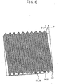
- FIG. 7 is a partial perspective view showing the structure of the heat exchanger in accordance with the second embodiment of the present invention.
- the heat exchanger in accordance with the second embodiment is formed in a structure as a heat exchanger 8 described in the above embodiment, and formed in a plate type having a plurality of through holes 72.
- the heat exchange member 70 in accordance with the second embodiment is formed in a corrugated plate shape at a predetermined angle and a plurality of through holes 72 through which air can pass are formed therein.
- the heat exchange member 70 is manufactured by punching a plurality of through holes on metal materials such as aluminum and the like, or paper materials.
- the heat exchange member can be formed with a porous resin film.
- the angle a that the heat exchange member is positioned is formed to be 30° ⁇ 60° slanted from the direction that the air flows as in the above embodiment.
- the heat exchange member has a mesh structure in which a plurality of holes are formed and is positioned a predetermined angle slanted from the direction that the air flows. Accordingly, as the air passing through the first and second air paths flows from the upper surface to the lower surface of the heat exchange member, or from the lower surface to the upper surface, turbulence is generated in the flowing air, and development of the boundary layer can be restricted, thus to improve heat transfer performance.
Landscapes
- Engineering & Computer Science (AREA)
- Mechanical Engineering (AREA)
- General Engineering & Computer Science (AREA)
- Physics & Mathematics (AREA)
- Thermal Sciences (AREA)
- Chemical & Material Sciences (AREA)
- Combustion & Propulsion (AREA)
- Heat-Exchange Devices With Radiators And Conduit Assemblies (AREA)
- Central Air Conditioning (AREA)
Claims (6)
- Échangeur de chaleur (8) d'un système de ventilation, comprenant :une pluralité de plaques d'échange de chaleur (50) empilées à un intervalle prédéterminé, un premier passage d'air (52) par lequel passe de l'air extérieur et un second passage d'air (56) par lequel passe de l'air intérieur étant respectivement situés entre des plaques d'échange de chaleur (50) adjacentes ;un premier élément échangeur de chaleur (54) qui s'étend entre les plaques d'échange de chaleur (50) formant le premier passage d'air (52) et conçu en forme de treillis pour accroître la turbulence de l'air extérieur qui circule dans le premier passage d'air (52) ; etun second élément échangeur de chaleur (58) qui s'étend entre les plaques d'échange de chaleur (50) formant le second passage d'air (56) qui croise le premier passage d'air (52) et conçu en forme de treillis pour accroître la turbulence de l'air extérieur qui circule dans le second passage d'air (56),dans lequel le premier (54) et le second (58) élément échangeur de chaleur comprennent une pluralité d'ondulations caractérisées par le fait que chaque ondulation est formée avec un angle prédéterminé d'obliquité par rapport au sens de circulation de l'air.
- Échangeur de chaleur (8) selon la revendication 1, dans lequel la plaque d'échange de chaleur est faite d'une plaque d'aluminium ou de matériaux à base de papier.
- Échangeur de chaleur (8) selon la revendication 1, dans lequel le premier (54) et le second (58) élément échangeur de chaleur sont positionnés de façon à fixer le premier (52) et le second (56) passage d'air entre les plaques d'échange de chaleur (50), et chacun est fait d'un matériau à base d'aluminium en forme de treillis, de telle sorte que l'air extérieur et intérieur amené au premier (52) et au second (56) passage d'air puisse passer de la surface supérieure à la surface inférieure des éléments échangeurs de chaleur (54, 58), ou de la surface inférieure à la surface supérieure.
- Échangeur de chaleur (8) selon la revendication 1, dans lequel le premier (54) et le second (58) élément échangeur de chaleur sont positionnés obliques de 30°-60° par rapport au sens de circulation de l'air.
- Échangeur de chaleur (8) selon la revendication 1, dans lequel le premier (54) et second (58) élément échangeur de chaleur sont positionnés de façon à fixer le premier (52) et le second (56) passage d'air entre les plaques d'échange de chaleur (50), et chacun est formé dans un type de plaque dans laquelle une pluralité de trous traversants sont formés, de telle sorte que l'air extérieur et intérieur circulant vers le premier (52) et le second (56) passage d'air puisse passer de la surface supérieure à la surface inférieure des éléments échangeurs de chaleur (54, 58), ou de la surface inférieure à la surface supérieure.
- Échangeur de chaleur (8) selon la revendication 5, dans lequel le premier (54) et le second (58) élément échangeur de chaleur sont dotés d'un film de résine poreuse.
Applications Claiming Priority (1)
| Application Number | Priority Date | Filing Date | Title |
|---|---|---|---|
| PCT/KR2002/002265 WO2004051172A2 (fr) | 2002-12-02 | 2002-12-02 | Echangeur thermique d'un systeme de ventilation |
Publications (2)
| Publication Number | Publication Date |
|---|---|
| EP1573260A2 EP1573260A2 (fr) | 2005-09-14 |
| EP1573260B1 true EP1573260B1 (fr) | 2008-03-19 |
Family
ID=32464304
Family Applications (1)
| Application Number | Title | Priority Date | Filing Date |
|---|---|---|---|
| EP02791012A Expired - Lifetime EP1573260B1 (fr) | 2002-12-02 | 2002-12-02 | Echangeur thermique d'un systeme de ventilation |
Country Status (8)
| Country | Link |
|---|---|
| US (1) | US7228891B2 (fr) |
| EP (1) | EP1573260B1 (fr) |
| CN (1) | CN1735783A (fr) |
| AT (1) | ATE389857T1 (fr) |
| AU (1) | AU2002368423B2 (fr) |
| DE (1) | DE60225734T2 (fr) |
| ES (1) | ES2301696T3 (fr) |
| WO (1) | WO2004051172A2 (fr) |
Families Citing this family (40)
| Publication number | Priority date | Publication date | Assignee | Title |
|---|---|---|---|---|
| US7185483B2 (en) * | 2003-01-21 | 2007-03-06 | General Electric Company | Methods and apparatus for exchanging heat |
| CA2487459A1 (fr) * | 2004-11-09 | 2006-05-09 | Venmar Ventilation Inc. | Coeur d'echangeur thermique avec entretoise metallique aplatie |
| TWI326691B (en) * | 2005-07-22 | 2010-07-01 | Kraton Polymers Res Bv | Sulfonated block copolymers, method for making same, and various uses for such block copolymers |
| EP1870657A1 (fr) * | 2006-06-24 | 2007-12-26 | Colbond B.V. | Échangeur de chaleur |
| KR100826023B1 (ko) * | 2006-12-28 | 2008-04-28 | 엘지전자 주식회사 | 환기 장치의 열교환기 |
| FR2913107B1 (fr) * | 2007-02-23 | 2009-05-08 | Pierre Vironneau | Procede pour realiser un echangeur thermique et echangeur thermique obtenu selon ce procede |
| US8590606B2 (en) * | 2007-06-18 | 2013-11-26 | Mitsubishi Electric Corporation | Heat exchange element and manufacturing method thereof, heat exchanger, and heat exchange ventilator |
| GB0720627D0 (en) * | 2007-10-19 | 2007-11-28 | Applied Cooling Technology Ltd | Turbulator for heat exchanger tube and method of manufacture |
| US20090260789A1 (en) * | 2008-04-21 | 2009-10-22 | Dana Canada Corporation | Heat exchanger with expanded metal turbulizer |
| JP2009264642A (ja) * | 2008-04-24 | 2009-11-12 | Panasonic Corp | 熱交換機器用風路構成板 |
| US8012539B2 (en) | 2008-05-09 | 2011-09-06 | Kraton Polymers U.S. Llc | Method for making sulfonated block copolymers, method for making membranes from such block copolymers and membrane structures |
| US8445631B2 (en) | 2009-10-13 | 2013-05-21 | Kraton Polymers U.S. Llc | Metal-neutralized sulfonated block copolymers, process for making them and their use |
| US8263713B2 (en) | 2009-10-13 | 2012-09-11 | Kraton Polymers U.S. Llc | Amine neutralized sulfonated block copolymers and method for making same |
| US8800308B2 (en) | 2010-05-25 | 2014-08-12 | 7Ac Technologies, Inc. | Methods and systems for desiccant air conditioning with combustion contaminant filtering |
| FI20105734A (fi) * | 2010-06-24 | 2011-12-25 | Vahterus Oy | Levylämmönsiirrin ja menetelmä levylämmönsiirtimen valmistamiseksi |
| CN101907408A (zh) * | 2010-07-30 | 2010-12-08 | 中国电力工程顾问集团东北电力设计院 | 火力发电厂表面式间接空冷系统板式凝汽器 |
| US9394414B2 (en) | 2010-09-29 | 2016-07-19 | Kraton Polymers U.S. Llc | Elastic, moisture-vapor permeable films, their preparation and their use |
| US9429366B2 (en) | 2010-09-29 | 2016-08-30 | Kraton Polymers U.S. Llc | Energy recovery ventilation sulfonated block copolymer laminate membrane |
| JP5802755B2 (ja) | 2010-10-18 | 2015-11-04 | クレイトン・ポリマーズ・ユー・エス・エル・エル・シー | スルホン化ブロックコポリマー組成物の製造方法 |
| US20120151934A1 (en) * | 2010-12-17 | 2012-06-21 | General Vortex Energy, Inc. | Recuperator with wire mesh |
| US8899309B2 (en) * | 2010-12-20 | 2014-12-02 | Daikin Industries, Ltd. | Ventilation device |
| CN102062551A (zh) * | 2011-01-19 | 2011-05-18 | 河北工程大学 | 流体热交换器 |
| US9310141B2 (en) | 2011-06-22 | 2016-04-12 | Gerald William Niebur | Counter current heat exchange module |
| US9861941B2 (en) | 2011-07-12 | 2018-01-09 | Kraton Polymers U.S. Llc | Modified sulfonated block copolymers and the preparation thereof |
| EP3686538A1 (fr) | 2012-06-11 | 2020-07-29 | 7AC Technologies, Inc. | Procédés et systèmes pour échangeurs de chaleur à écoulement turbulent résistants à la corrosion |
| US20140014289A1 (en) * | 2012-07-11 | 2014-01-16 | Kraton Polymers U.S. Llc | Enhanced-efficiency energy recovery ventilation core |
| US9631848B2 (en) | 2013-03-01 | 2017-04-25 | 7Ac Technologies, Inc. | Desiccant air conditioning systems with conditioner and regenerator heat transfer fluid loops |
| US20140260399A1 (en) | 2013-03-14 | 2014-09-18 | 7Ac Technologies, Inc. | Methods and systems for mini-split liquid desiccant air conditioning |
| EP3667191B1 (fr) | 2013-06-12 | 2024-05-29 | Copeland LP | Système de climatisation à déshydratant liquide et procédé de déshumidification et de refroidissement d'un flux d'air dans un bâtiment |
| EP3071893B1 (fr) * | 2013-11-19 | 2019-03-06 | 7AC Technologies, Inc. | Procédés et systèmes pour échangeurs de chaleur résistants à la corrosion, à écoulement turbulent |
| JP6674382B2 (ja) | 2014-03-20 | 2020-04-01 | 7エーシー テクノロジーズ,インコーポレイテッド | 屋上型液体乾燥剤システム及び方法 |
| US9630132B2 (en) * | 2014-07-01 | 2017-04-25 | Caterpillar Inc. | Fluid filtering system |
| CN107110525B (zh) | 2014-11-21 | 2020-02-11 | 7Ac技术公司 | 用于微分体液体干燥剂空气调节的方法和系统 |
| DE102014017362A1 (de) * | 2014-11-24 | 2016-05-25 | Klingenburg Gmbh | Plattenelement für einen Plattenwärmetauscher |
| US20220163272A1 (en) * | 2017-05-18 | 2022-05-26 | Kai Klingenburg | Heat-exchanger plate |
| CN111448425A (zh) | 2017-11-01 | 2020-07-24 | 7Ac技术公司 | 用于液体干燥剂空调系统的储罐系统 |
| WO2019089957A1 (fr) | 2017-11-01 | 2019-05-09 | 7Ac Technologies, Inc. | Procédés et appareil de distribution uniforme de déshydratant liquide dans des modules de membrane dans des systèmes de climatisation à déshydratant liquide |
| US11022330B2 (en) | 2018-05-18 | 2021-06-01 | Emerson Climate Technologies, Inc. | Three-way heat exchangers for liquid desiccant air-conditioning systems and methods of manufacture |
| CN109974488B (zh) * | 2019-04-22 | 2024-04-30 | 佛山市科蓝环保科技股份有限公司 | 换热结构及带有该换热结构的换热装置 |
| CN113587706B (zh) * | 2021-08-01 | 2022-11-04 | 北京工业大学 | 一种折叠式换热器及其整体式新风空调机 |
Family Cites Families (13)
| Publication number | Priority date | Publication date | Assignee | Title |
|---|---|---|---|---|
| US1458128A (en) * | 1919-10-13 | 1923-06-12 | Edward T Curran | Radiator |
| US2314966A (en) * | 1937-03-29 | 1943-03-30 | Astle William | Plate heat exchanger |
| US2616671A (en) * | 1949-02-16 | 1952-11-04 | Creamery Package Mfg Co | Plate heat exchanger |
| US3666007A (en) * | 1970-03-17 | 1972-05-30 | Mitsubishi Electric Corp | Apparatus for effecting continuous and simultaneous transfer of heat and moisture between two air streams |
| DE2333697A1 (de) | 1973-07-03 | 1975-01-23 | Kloeckner Humboldt Deutz Ag | Rekuperativer plattenwaermetauscher |
| US5031693A (en) * | 1990-10-31 | 1991-07-16 | Sundstrand Corporation | Jet impingement plate fin heat exchanger |
| JP3203037B2 (ja) | 1992-04-02 | 2001-08-27 | エムイーシープラント株式会社 | 物質および/または熱交換塔用の充填材 |
| SE470339B (sv) * | 1992-06-12 | 1994-01-24 | Alfa Laval Thermal | Plattvärmeväxlare för vätskor med olika flöden |
| US6127571A (en) * | 1997-11-11 | 2000-10-03 | Uop Llc | Controlled reactant injection with permeable plates |
| US6145588A (en) * | 1998-08-03 | 2000-11-14 | Xetex, Inc. | Air-to-air heat and moisture exchanger incorporating a composite material for separating moisture from air technical field |
| KR20000010461U (ko) | 1998-11-21 | 2000-06-15 | 장병주 | 열회수식 환기시스템에서의 열교환 소자 |
| WO2001027552A1 (fr) * | 1999-10-08 | 2001-04-19 | Carrier Corporation | Echangeur thermique du type plaque |
| FR2811747B1 (fr) * | 2000-07-11 | 2002-10-11 | Air Liquide | Ailette d'echange thermique pour echangeur de chaleur a plaques brasees, et echangeur de chaleur correspondant |
-
2002
- 2002-12-02 CN CNA02830179XA patent/CN1735783A/zh active Pending
- 2002-12-02 ES ES02791012T patent/ES2301696T3/es not_active Expired - Lifetime
- 2002-12-02 US US10/536,959 patent/US7228891B2/en not_active Expired - Fee Related
- 2002-12-02 AU AU2002368423A patent/AU2002368423B2/en not_active Ceased
- 2002-12-02 DE DE60225734T patent/DE60225734T2/de not_active Expired - Lifetime
- 2002-12-02 WO PCT/KR2002/002265 patent/WO2004051172A2/fr not_active Application Discontinuation
- 2002-12-02 EP EP02791012A patent/EP1573260B1/fr not_active Expired - Lifetime
- 2002-12-02 AT AT02791012T patent/ATE389857T1/de not_active IP Right Cessation
Also Published As
| Publication number | Publication date |
|---|---|
| AU2002368423A1 (en) | 2004-06-23 |
| DE60225734T2 (de) | 2009-04-23 |
| US7228891B2 (en) | 2007-06-12 |
| AU2002368423B2 (en) | 2007-08-23 |
| DE60225734D1 (de) | 2008-04-30 |
| ATE389857T1 (de) | 2008-04-15 |
| CN1735783A (zh) | 2006-02-15 |
| ES2301696T3 (es) | 2008-07-01 |
| US20060070728A1 (en) | 2006-04-06 |
| WO2004051172A2 (fr) | 2004-06-17 |
| WO2004051172A3 (fr) | 2005-03-03 |
| EP1573260A2 (fr) | 2005-09-14 |
Similar Documents
| Publication | Publication Date | Title |
|---|---|---|
| EP1573260B1 (fr) | Echangeur thermique d'un systeme de ventilation | |
| JP3577863B2 (ja) | 対向流型熱交換器 | |
| EP1573262B1 (fr) | Echangeur de chaleur d'un systeme de ventilation | |
| US7147049B2 (en) | Heat exchanger of ventilating system | |
| US7237603B2 (en) | Heat exchanger of ventilating system | |
| JP2009121727A (ja) | 全熱交換型換気装置 | |
| EP1680638B1 (fr) | Echangeur de chaleur pour ventilateur | |
| EP1704377B1 (fr) | Echangeur thermique destine a un ventilateur | |
| KR100898926B1 (ko) | 환기 장치용 열교환기 | |
| KR100908257B1 (ko) | 공기조화기용 열교환소자 조립체 | |
| KR20000010461U (ko) | 열회수식 환기시스템에서의 열교환 소자 | |
| JP2001174172A (ja) | 熱交換素子 | |
| JPH0136013B2 (fr) | ||
| KR20050086741A (ko) | 환기 장치용 열교환기 | |
| KR20050087796A (ko) | 환기 장치용 열교환기 | |
| KR20050089801A (ko) | 환기 장치용 열교환기 | |
| KR20040040176A (ko) | 공기조화기용 열교환소자 조립체 | |
| KR20040040166A (ko) | 공기조화기용 열교환소자 조립체 |
Legal Events
| Date | Code | Title | Description |
|---|---|---|---|
| PUAI | Public reference made under article 153(3) epc to a published international application that has entered the european phase |
Free format text: ORIGINAL CODE: 0009012 |
|
| 17P | Request for examination filed |
Effective date: 20050609 |
|
| AK | Designated contracting states |
Kind code of ref document: A2 Designated state(s): AT BE BG CH CY CZ DE DK EE ES FI FR GB GR IE IT LI LU MC NL PT SE SI SK TR |
|
| AX | Request for extension of the european patent |
Extension state: AL LT LV MK RO |
|
| DAX | Request for extension of the european patent (deleted) | ||
| 17Q | First examination report despatched |
Effective date: 20061011 |
|
| 17Q | First examination report despatched |
Effective date: 20061011 |
|
| GRAP | Despatch of communication of intention to grant a patent |
Free format text: ORIGINAL CODE: EPIDOSNIGR1 |
|
| RAP1 | Party data changed (applicant data changed or rights of an application transferred) |
Owner name: LG ELECTRONICS INC. |
|
| GRAS | Grant fee paid |
Free format text: ORIGINAL CODE: EPIDOSNIGR3 |
|
| GRAA | (expected) grant |
Free format text: ORIGINAL CODE: 0009210 |
|
| AK | Designated contracting states |
Kind code of ref document: B1 Designated state(s): AT BE BG CH CY CZ DE DK EE ES FI FR GB GR IE IT LI LU MC NL PT SE SI SK TR |
|
| REG | Reference to a national code |
Ref country code: GB Ref legal event code: FG4D |
|
| RIN1 | Information on inventor provided before grant (corrected) |
Inventor name: SHIN, SOO-YEON,BOOYOUNG APT. Inventor name: CHO, MIN-CHUL Inventor name: LEE, SEONG-HWAN Inventor name: LEE, SUNG-HWA |
|
| REG | Reference to a national code |
Ref country code: CH Ref legal event code: EP |
|
| REF | Corresponds to: |
Ref document number: 60225734 Country of ref document: DE Date of ref document: 20080430 Kind code of ref document: P |
|
| REG | Reference to a national code |
Ref country code: IE Ref legal event code: FG4D |
|
| REG | Reference to a national code |
Ref country code: ES Ref legal event code: FG2A Ref document number: 2301696 Country of ref document: ES Kind code of ref document: T3 |
|
| PG25 | Lapsed in a contracting state [announced via postgrant information from national office to epo] |
Ref country code: FI Free format text: LAPSE BECAUSE OF FAILURE TO SUBMIT A TRANSLATION OF THE DESCRIPTION OR TO PAY THE FEE WITHIN THE PRESCRIBED TIME-LIMIT Effective date: 20080319 |
|
| PG25 | Lapsed in a contracting state [announced via postgrant information from national office to epo] |
Ref country code: AT Free format text: LAPSE BECAUSE OF FAILURE TO SUBMIT A TRANSLATION OF THE DESCRIPTION OR TO PAY THE FEE WITHIN THE PRESCRIBED TIME-LIMIT Effective date: 20080319 |
|
| NLV1 | Nl: lapsed or annulled due to failure to fulfill the requirements of art. 29p and 29m of the patents act | ||
| PG25 | Lapsed in a contracting state [announced via postgrant information from national office to epo] |
Ref country code: BE Free format text: LAPSE BECAUSE OF FAILURE TO SUBMIT A TRANSLATION OF THE DESCRIPTION OR TO PAY THE FEE WITHIN THE PRESCRIBED TIME-LIMIT Effective date: 20080319 Ref country code: SI Free format text: LAPSE BECAUSE OF FAILURE TO SUBMIT A TRANSLATION OF THE DESCRIPTION OR TO PAY THE FEE WITHIN THE PRESCRIBED TIME-LIMIT Effective date: 20080319 |
|
| PG25 | Lapsed in a contracting state [announced via postgrant information from national office to epo] |
Ref country code: SK Free format text: LAPSE BECAUSE OF FAILURE TO SUBMIT A TRANSLATION OF THE DESCRIPTION OR TO PAY THE FEE WITHIN THE PRESCRIBED TIME-LIMIT Effective date: 20080319 Ref country code: SE Free format text: LAPSE BECAUSE OF FAILURE TO SUBMIT A TRANSLATION OF THE DESCRIPTION OR TO PAY THE FEE WITHIN THE PRESCRIBED TIME-LIMIT Effective date: 20080619 Ref country code: PT Free format text: LAPSE BECAUSE OF FAILURE TO SUBMIT A TRANSLATION OF THE DESCRIPTION OR TO PAY THE FEE WITHIN THE PRESCRIBED TIME-LIMIT Effective date: 20080826 Ref country code: CZ Free format text: LAPSE BECAUSE OF FAILURE TO SUBMIT A TRANSLATION OF THE DESCRIPTION OR TO PAY THE FEE WITHIN THE PRESCRIBED TIME-LIMIT Effective date: 20080319 |
|
| PG25 | Lapsed in a contracting state [announced via postgrant information from national office to epo] |
Ref country code: NL Free format text: LAPSE BECAUSE OF FAILURE TO SUBMIT A TRANSLATION OF THE DESCRIPTION OR TO PAY THE FEE WITHIN THE PRESCRIBED TIME-LIMIT Effective date: 20080319 |
|
| EN | Fr: translation not filed | ||
| PLBE | No opposition filed within time limit |
Free format text: ORIGINAL CODE: 0009261 |
|
| STAA | Information on the status of an ep patent application or granted ep patent |
Free format text: STATUS: NO OPPOSITION FILED WITHIN TIME LIMIT |
|
| PG25 | Lapsed in a contracting state [announced via postgrant information from national office to epo] |
Ref country code: DK Free format text: LAPSE BECAUSE OF FAILURE TO SUBMIT A TRANSLATION OF THE DESCRIPTION OR TO PAY THE FEE WITHIN THE PRESCRIBED TIME-LIMIT Effective date: 20080319 |
|
| 26N | No opposition filed |
Effective date: 20081222 |
|
| PG25 | Lapsed in a contracting state [announced via postgrant information from national office to epo] |
Ref country code: EE Free format text: LAPSE BECAUSE OF FAILURE TO SUBMIT A TRANSLATION OF THE DESCRIPTION OR TO PAY THE FEE WITHIN THE PRESCRIBED TIME-LIMIT Effective date: 20080319 Ref country code: BG Free format text: LAPSE BECAUSE OF FAILURE TO SUBMIT A TRANSLATION OF THE DESCRIPTION OR TO PAY THE FEE WITHIN THE PRESCRIBED TIME-LIMIT Effective date: 20080619 |
|
| PG25 | Lapsed in a contracting state [announced via postgrant information from national office to epo] |
Ref country code: MC Free format text: LAPSE BECAUSE OF NON-PAYMENT OF DUE FEES Effective date: 20081231 |
|
| REG | Reference to a national code |
Ref country code: CH Ref legal event code: PL |
|
| PG25 | Lapsed in a contracting state [announced via postgrant information from national office to epo] |
Ref country code: CY Free format text: LAPSE BECAUSE OF FAILURE TO SUBMIT A TRANSLATION OF THE DESCRIPTION OR TO PAY THE FEE WITHIN THE PRESCRIBED TIME-LIMIT Effective date: 20080319 |
|
| PG25 | Lapsed in a contracting state [announced via postgrant information from national office to epo] |
Ref country code: CH Free format text: LAPSE BECAUSE OF NON-PAYMENT OF DUE FEES Effective date: 20081231 Ref country code: IE Free format text: LAPSE BECAUSE OF NON-PAYMENT OF DUE FEES Effective date: 20081202 Ref country code: LI Free format text: LAPSE BECAUSE OF NON-PAYMENT OF DUE FEES Effective date: 20081231 |
|
| PG25 | Lapsed in a contracting state [announced via postgrant information from national office to epo] |
Ref country code: LU Free format text: LAPSE BECAUSE OF NON-PAYMENT OF DUE FEES Effective date: 20081202 |
|
| PG25 | Lapsed in a contracting state [announced via postgrant information from national office to epo] |
Ref country code: TR Free format text: LAPSE BECAUSE OF FAILURE TO SUBMIT A TRANSLATION OF THE DESCRIPTION OR TO PAY THE FEE WITHIN THE PRESCRIBED TIME-LIMIT Effective date: 20080319 |
|
| PG25 | Lapsed in a contracting state [announced via postgrant information from national office to epo] |
Ref country code: GR Free format text: LAPSE BECAUSE OF FAILURE TO SUBMIT A TRANSLATION OF THE DESCRIPTION OR TO PAY THE FEE WITHIN THE PRESCRIBED TIME-LIMIT Effective date: 20080620 |
|
| PG25 | Lapsed in a contracting state [announced via postgrant information from national office to epo] |
Ref country code: FR Free format text: LAPSE BECAUSE OF FAILURE TO SUBMIT A TRANSLATION OF THE DESCRIPTION OR TO PAY THE FEE WITHIN THE PRESCRIBED TIME-LIMIT Effective date: 20090109 |
|
| PGFP | Annual fee paid to national office [announced via postgrant information from national office to epo] |
Ref country code: DE Payment date: 20161107 Year of fee payment: 15 Ref country code: GB Payment date: 20161110 Year of fee payment: 15 |
|
| PGFP | Annual fee paid to national office [announced via postgrant information from national office to epo] |
Ref country code: IT Payment date: 20161214 Year of fee payment: 15 Ref country code: ES Payment date: 20161118 Year of fee payment: 15 |
|
| REG | Reference to a national code |
Ref country code: DE Ref legal event code: R119 Ref document number: 60225734 Country of ref document: DE |
|
| GBPC | Gb: european patent ceased through non-payment of renewal fee |
Effective date: 20171202 |
|
| PG25 | Lapsed in a contracting state [announced via postgrant information from national office to epo] |
Ref country code: DE Free format text: LAPSE BECAUSE OF NON-PAYMENT OF DUE FEES Effective date: 20180703 Ref country code: IT Free format text: LAPSE BECAUSE OF NON-PAYMENT OF DUE FEES Effective date: 20171202 |
|
| PG25 | Lapsed in a contracting state [announced via postgrant information from national office to epo] |
Ref country code: GB Free format text: LAPSE BECAUSE OF NON-PAYMENT OF DUE FEES Effective date: 20171202 |
|
| REG | Reference to a national code |
Ref country code: ES Ref legal event code: FD2A Effective date: 20190702 |
|
| PG25 | Lapsed in a contracting state [announced via postgrant information from national office to epo] |
Ref country code: ES Free format text: LAPSE BECAUSE OF NON-PAYMENT OF DUE FEES Effective date: 20171203 |