EP1573211B1 - Dispositif de diagnostic d'etat d'un composant hydraulique, en particulier un cylindre hydraulique - Google Patents
Dispositif de diagnostic d'etat d'un composant hydraulique, en particulier un cylindre hydraulique Download PDFInfo
- Publication number
- EP1573211B1 EP1573211B1 EP03789082A EP03789082A EP1573211B1 EP 1573211 B1 EP1573211 B1 EP 1573211B1 EP 03789082 A EP03789082 A EP 03789082A EP 03789082 A EP03789082 A EP 03789082A EP 1573211 B1 EP1573211 B1 EP 1573211B1
- Authority
- EP
- European Patent Office
- Prior art keywords
- fluid
- control
- diagnostic module
- lines
- data
- Prior art date
- Legal status (The legal status is an assumption and is not a legal conclusion. Google has not performed a legal analysis and makes no representation as to the accuracy of the status listed.)
- Expired - Lifetime
Links
- 238000003745 diagnosis Methods 0.000 title claims abstract description 12
- 239000012530 fluid Substances 0.000 claims abstract description 82
- 230000005540 biological transmission Effects 0.000 claims abstract description 9
- 230000003287 optical effect Effects 0.000 claims abstract description 9
- 238000012544 monitoring process Methods 0.000 claims abstract 7
- 230000000712 assembly Effects 0.000 claims description 4
- 238000000429 assembly Methods 0.000 claims description 4
- 238000001514 detection method Methods 0.000 claims description 2
- 238000010079 rubber tapping Methods 0.000 claims description 2
- 238000005259 measurement Methods 0.000 abstract 1
- 230000008878 coupling Effects 0.000 description 8
- 238000010168 coupling process Methods 0.000 description 8
- 238000005859 coupling reaction Methods 0.000 description 8
- 238000009434 installation Methods 0.000 description 3
- 230000013011 mating Effects 0.000 description 3
- 230000008901 benefit Effects 0.000 description 2
- 230000009467 reduction Effects 0.000 description 2
- 238000004891 communication Methods 0.000 description 1
- 239000004020 conductor Substances 0.000 description 1
- 230000001419 dependent effect Effects 0.000 description 1
- 238000013461 design Methods 0.000 description 1
- 238000011156 evaluation Methods 0.000 description 1
- 238000012423 maintenance Methods 0.000 description 1
- 238000012986 modification Methods 0.000 description 1
- 230000004048 modification Effects 0.000 description 1
- 238000012546 transfer Methods 0.000 description 1
Images

Classifications
-
- F—MECHANICAL ENGINEERING; LIGHTING; HEATING; WEAPONS; BLASTING
- F15—FLUID-PRESSURE ACTUATORS; HYDRAULICS OR PNEUMATICS IN GENERAL
- F15B—SYSTEMS ACTING BY MEANS OF FLUIDS IN GENERAL; FLUID-PRESSURE ACTUATORS, e.g. SERVOMOTORS; DETAILS OF FLUID-PRESSURE SYSTEMS, NOT OTHERWISE PROVIDED FOR
- F15B19/00—Testing; Calibrating; Fault detection or monitoring; Simulation or modelling of fluid-pressure systems or apparatus not otherwise provided for
- F15B19/005—Fault detection or monitoring
-
- F—MECHANICAL ENGINEERING; LIGHTING; HEATING; WEAPONS; BLASTING
- F15—FLUID-PRESSURE ACTUATORS; HYDRAULICS OR PNEUMATICS IN GENERAL
- F15B—SYSTEMS ACTING BY MEANS OF FLUIDS IN GENERAL; FLUID-PRESSURE ACTUATORS, e.g. SERVOMOTORS; DETAILS OF FLUID-PRESSURE SYSTEMS, NOT OTHERWISE PROVIDED FOR
- F15B15/00—Fluid-actuated devices for displacing a member from one position to another; Gearing associated therewith
- F15B15/20—Other details, e.g. assembly with regulating devices
- F15B15/28—Means for indicating the position, e.g. end of stroke
- F15B15/2815—Position sensing, i.e. means for continuous measurement of position, e.g. LVDT
- F15B15/2838—Position sensing, i.e. means for continuous measurement of position, e.g. LVDT with out using position sensors, e.g. by volume flow measurement or pump speed
Definitions
- the invention relates to a device for condition diagnosis of a fluidic cylinder according to the preamble of claim 1.
- a measuring arrangement or a computer module which merely serves for diagnosis, that is, interrogates and checks measuring and sensor data.
- the control of the known fluidic cylinder must be done via a separate arrangement. This leads to a multiplication of connecting lines.
- US-A-5 823 088 discloses fluidic cylinders provided with control valve assemblies, but does not address diagnostic functions.
- An object of the present invention is to provide a device of the type mentioned, in which the assembly cost is substantially reduced.
- the diagnostic module is arranged in a simple manner only by mating with one or two fluid lines between the fluid source and the fluidic cylinder.
- the integrated electrical or optical lines eg light guides
- the control, diagnostic connections and / or energy transmission connections are produced at the same time, so that essentially no additional wiring is required.
- the diagnostic module for data acquisition and for controlling the fluidic cylinder via the control valve assembly only has to be connected to the fluidic cylinder.
- the simple mating allows a very quick and easy installation with a minimum number of lines, which also avoids errors due to incorrect wiring.
- the diagnostic module is arranged directly on the fluidic cylinder and connected via a fluid line to the fluid source, wherein the electrical or optical lines of the fluid line transmission lines for data and supply energy. It must therefore simply plugged together the diagnostic module with the fluidic cylinder and a fluid line between the diagnostic module and the fluid source are plugged in a simple manner.
- the diagnostic module is arranged directly on the fluid source and connected to the fluidic cylinder via a corresponding fluid line.
- the installation effort is correspondingly low here.
- Another advantage is the use of the common fluid source and a common communication interface (e.g., fieldbus connection).
- the diagnostic module is arranged neither on the fluidic cylinder nor on the fluid source, but connected via a first fluid line to the fluid source and via a second fluid line to the fluidic cylinder.
- the electrical or optical and fluidic assembly can be done by simply mating with the two fluid lines.
- the electrical lines of the second fluid line are control and / or transmission lines for supply energy, that is, for example, supply energy for a control valve on the fluidic cylinder.
- the control and / or monitoring center can be arranged either in a device also having the fluid source or externally.
- an electrical branching or tapping element is expediently provided in the first fluid line for connecting an electrical cable leading to the externally arranged control and / or monitoring center.
- the diagnostic module can also be connected directly via a cable to the externally arranged control and / or monitoring center.
- the device having the fluid source is provided with valve arrangements, for example a valve battery or a component thereof.
- the diagnostic module is preferably additionally provided with a pressure sensor and / or a temperature sensor. Furthermore, a sensor for detecting the electric current to the fluidic cylinder may be included.
- the microcomputer is designed in the diagnostic module for evaluating the diagnostic data and transmitting it to the control and / or monitoring center, in particular also for receiving control data.
- a controllable by the microcomputer for switching the to the fluidic cylinder leading control and / or supply power line.
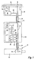
- a fluid source 10 is connected via a fluid channel 11 to a fluidic component 12, which is designed as a fluidic cylinder 13 with an integrated control valve 14.
- the fluidic cylinder 13 can be designed as a single- or double-acting cylinder.
- the fluid source 10 may be a simple branch 15 from a supply channel 16, but the fluid source 10 may also be a fluidic maintenance unit, for example or valve battery may be formed, which has a control and / or data bus 17 which is connected to an internal or external, not shown in Figure 1 control and / or monitoring center.
- the control and / or data bus 17 also has additional power lines, all lines being shown for simplicity only by a single line.
- a coupling member 18 is connected both via a bus terminal 19 to the control and / or data bus 17 and to the corresponding power lines. In the coupling member 18, data and energy are then coupled and supplied to a common data / power line 20.
- the fluid channel 11 between the fluid source 10 and fluidic component 12 consists of the series connection of a first fluid line 21, a through-line 22 through a diagnostic module 23 and a second fluid line 24.
- the two fluid lines 21 and 24 each have on or in the walls integrated electrical lines to the data - and / or energy transfer. These are generally two lines, although the number may be higher. Instead of electrical lines, optical lines may also be provided, e.g. Light guide.
- the coupling member 18 in the fluid source 10 is electrically connected via the data / power line 20 to a coupling member 25 in the diagnostic module 23.
- the data / power line 20 is formed along the first fluid line 21 by its integrated electrical conductor in the wall.
- the coupling member 25 serves to decouple the received electrical or optical signals into data and energy.
- the data is fed to a microcomputer 26 while the decoupled energy is supplied via a power switch 27, a current measuring sensor 28 and the integrated lines in the second Fluid line 24 is the control valve 14 of the fluid power component 12 is supplied.
- a flow sensor 29 a pressure sensor 30 and a temperature sensor 31
- the corresponding parameters of the fluid in the passage line 22 are detected and supplied to the microcomputer 26.
- the fluid source 10, the diagnostic module 23 and the fluid power component 12 are connected to each other by simply plugging together with the two fluid lines 21, 24. In each case, the fluidic and the electrical or optical connections are made simultaneously.
- the fluid lines 21 and 24 preferably have the same design.
- a control signal for the control valve 14 is transmitted from the control and / or data bus 17 to the microcomputer 26. This converts the data into control signals for the power switch 27, through which the control valve 14 is actuated.
- the respective states and positions of the fluidic cylinder 13 in the microcomputer 26 are detected by comparison with stored characteristic curves or characteristic curve values. This is described in more detail in DE 19628221 C2 cited at the outset. In this way, position and limit switches on the fluidic cylinder 13 or other actuators or components can be saved.
- the status data acquired in this way can be transmitted via the coupling element 25, the data / power line 20, the coupling element 18 and the bus connection element 19 to the control and / or data bus 17, from where they can be transmitted to a control and / or monitoring center , which is not shown in detail.
- the microcomputer 26 can also have its own control intelligence have, so that it controls the circuit breaker according to a predetermined program depending on the detected state data.
- the current measured by means of the current measuring sensor 28 to the valve coil of the control valve 14 can cooperate both to form the state data and to control the circuit breaker 27.
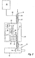
- the second embodiment shown in Figure 2 shows many similarities with the first embodiment, wherein the same or equivalent components and assemblies are provided with the same reference numerals and not described again.
- the data / power line 20, starting from the coupling member 25 in the diagnostic module 23 is not connected to an electronics in the fluid source 10, but directly to an external control and / or monitoring center 32.
- a branch element 33 is provided in the first fluid line 21, through which the data / power line 20 is branched out of the first fluid line 21 and guided to the control and / or monitoring center 32. It is of course also possible to branch off only one data line to the control and / or monitoring center 32, while a power line is still led to the fluid source 10.
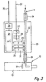
- a first fluidic line 34 occurs here between the fluid source 10, not shown here, and the diagnostic module 23, which contains no electrical lines.
- the microcomputer 26 is directly via an electrical interface 35 and at least one data line 36, for example, as an I / O control line or field bus may be formed, connected to the external control and / or monitoring center, not shown here.
- the power switch 27 is connected via a Vesorgungs effet 37 with a supply voltage source.
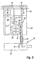
- the diagnostic module 23 is arranged directly on the fluidic component 12, or connected thereto or integrated therein.
- the second fluid line 24 is therefore eliminated.
- this embodiment corresponds to the first embodiment shown in FIG.
- the diagnostic module 23 is disposed directly on the fluid source 10 and connected thereto.
- the first fluid line 21 or 34 is therefore eliminated.
- the microcomputer 26 of the diagnostic module 23 is connected directly via the bus terminal 19 to the control and / or data bus 17 of the fluid source 10. Accordingly, the power switch 27 is directly connected to corresponding power lines of the control and / or data bus 17.
Claims (13)
- Dispositif de diagnostic d'état d'un cylindre hydraulique, qui est relié via au moins un canal fluidique (11) à une source de fluide, avec un module de diagnostic (23) électronique destiné au diagnostic de l'état du cylindre hydraulique (13) au moins par détection du débit hydraulique au moyen d'un débitmètre (29), le module de diagnostic (23) possédant au moins une conduite de passage (22) fluidique intégrée qui est dotée pour le diagnostic d'un débitmètre (29), et qui forme, conjointement à au moins une conduite fluidique montée en série (21, 24, 34), le canal fluidique (11), et le module de diagnostic (23) étant en connexion avec une centrale de commande et/ou de contrôle (32) recevant des données de diagnostic, caractérisé en ce qu'au moins une des lignes fluidiques (21, 24) est équipée d'au moins deux lignes électriques ou optiques intégrées pour la transmission de données et/ou d'énergie, en ce que le cylindre hydraulique (13) est équipé d'un dispositif de soupapes de commande (14) et en ce qu'un microordinateur (26) est prévu dans le module de diagnostic pour la commande du cylindre hydraulique (13).
- Dispositif selon la revendication 1, caractérisé en ce que le module de diagnostic (23) est disposé sur le cylindre hydraulique (13) et est relié via une conduite hydraulique (21) à la source de fluide (10), les lignes électriques (20) de la conduite fluidique (21) étant des lignes de transmission pour des données et pour l'énergie d'alimentation.
- Dispositif selon la revendication 1, caractérisé en ce que le module de diagnostic (23) est disposé sur la source de fluide (10) et est relié via une conduite fluidique correspondante (24) au cylindre hydraulique (13), les lignes électriques de la conduite fluidique (24) étant des lignes de transmission pour l'énergie d'alimentation.
- Dispositif selon la revendication 1, caractérisé en ce que le module de diagnostic (23) est relié via une première conduite fluidique (21 ; 34) à la source de fluide (10) et est relié via une seconde conduite fluidique (24) au cylindre hydraulique (13).
- Dispositif selon la revendication 4, caractérisé en ce que les lignes électriques de la seconde conduite fluidique (24) sont des lignes de transmission pour l'énergie d'alimentation ou des lignes de commande.
- Dispositif selon la revendication 4 ou 5, caractérisé en ce que les lignes électriques de la première conduite hydraulique (21) sont des conduites de transmission pour les données et pour l'énergie d'alimentation.
- Dispositif selon une des revendications précédentes, caractérisé en ce qu'une installation comprenant la source de fluide (10) comprend la centrale de commande et de contrôle, ou un bus de données (17) menant à celle-ci.
- Dispositif selon la revendication 6, caractérisé en ce que dans la première conduite fluidique (21) est prévu un élément de dérivation ou de branchement électrique (33) pour le raccordement d'un câble électrique conduisant à la centrale de commande et de contrôle (32) disposée en externe.
- Dispositif selon la revendication 4 ou 5, caractérisé en ce que le module de diagnostic (23) est relié via des câbles (36, 37) à la centrale de commande et de contrôle (32) disposée en externe.
- Dispositif selon une des revendications précédentes, caractérisé en ce que la source de fluide comprend des dispositifs de soupapes et/ou est conçue comme une unité de maintenance fluidique ou des composants d'une batterie de soupapes.
- Dispositif selon une des revendications précédentes, caractérisé en ce que le module de diagnostic (23) comprend en plus un capteur de pression (30) et/ou un capteur de température (31) et/ou un capteur (28) pour le courant électrique dirigé vers le cylindre hydraulique (13).
- Dispositif selon une des revendications précédentes, caractérisé en ce que le microordinateur (26) dans le module de diagnostic (23) est configuré pour la réception des données de commande par la centrale de commande et/ou de contrôle (32) et/ou pour l'exploitation des données de diagnostic et la transmission de celles-ci vers la centrale de commande et/ou de contrôle (32).
- Dispositif selon une des revendications précédentes, caractérisé en ce que le module de diagnostic (23) comprend un commutateur (27) contrôlable destiné à la commutation de la ligne électrique menant au cylindre hydraulique (13) à travers le microordinateur (26).
Applications Claiming Priority (3)
| Application Number | Priority Date | Filing Date | Title |
|---|---|---|---|
| DE10259394A DE10259394A1 (de) | 2002-12-19 | 2002-12-19 | Vorrichtung zur Zustandsdiagnose einer fluidtechnischen Komponente, insbesondere eines Fluidikzylinders |
| DE10259394 | 2002-12-19 | ||
| PCT/EP2003/013264 WO2004057197A1 (fr) | 2002-12-19 | 2003-11-26 | Dispositif de diagnostic d'etat d'un composant hydraulique, en particulier un cylindre hydraulique |
Publications (2)
| Publication Number | Publication Date |
|---|---|
| EP1573211A1 EP1573211A1 (fr) | 2005-09-14 |
| EP1573211B1 true EP1573211B1 (fr) | 2007-05-30 |
Family
ID=32519104
Family Applications (1)
| Application Number | Title | Priority Date | Filing Date |
|---|---|---|---|
| EP03789082A Expired - Lifetime EP1573211B1 (fr) | 2002-12-19 | 2003-11-26 | Dispositif de diagnostic d'etat d'un composant hydraulique, en particulier un cylindre hydraulique |
Country Status (5)
| Country | Link |
|---|---|
| EP (1) | EP1573211B1 (fr) |
| AT (1) | ATE363603T1 (fr) |
| DE (2) | DE10259394A1 (fr) |
| DK (1) | DK1573211T3 (fr) |
| WO (1) | WO2004057197A1 (fr) |
Families Citing this family (5)
| Publication number | Priority date | Publication date | Assignee | Title |
|---|---|---|---|---|
| DE102007010115A1 (de) | 2007-02-28 | 2008-09-04 | Robert Bosch Gmbh | Pneumatikantrieb mit Zylinderschalter |
| WO2010022746A1 (fr) * | 2008-08-26 | 2010-03-04 | Navalimpianti S.P.A. | Dispositif de mesure pour la mesure de la position d'actionneurs hydrauliques avec régulation |
| US20130060519A1 (en) * | 2010-05-06 | 2013-03-07 | Scandinavian Construction Comp. A/S | Encoder to determine the position of a piston in a hydraulic or a pneumatic cylinder |
| ITPR20120042A1 (it) * | 2012-07-02 | 2014-01-03 | Dvg Automation S P A | Apparecchio di comando e controllo delle funzioni di un attuatore |
| DE202015006675U1 (de) | 2015-09-25 | 2015-11-09 | Aventics Gmbh | Hilfsvorrichtung zur Einstellung der Endlagendämpfung pneumatischer Zylinder |
Family Cites Families (8)
| Publication number | Priority date | Publication date | Assignee | Title |
|---|---|---|---|---|
| EP0803653B1 (fr) * | 1996-04-26 | 2000-08-02 | Hygrama Ag | Système pneumatique de commande |
| DE19628221C2 (de) * | 1996-07-15 | 2000-05-31 | Festo Ag & Co | Verfahren und Vorrichtung zur Bestimmung von Betriebspositionen einer Arbeitseinrichtung |
| WO2001066957A2 (fr) * | 2000-03-08 | 2001-09-13 | Rosemount Inc. | Dispositif et procede de mesure pour piston d'actionneur hydraulique |
| US20010037689A1 (en) * | 2000-03-08 | 2001-11-08 | Krouth Terrance F. | Hydraulic actuator piston measurement apparatus and method |
| US6748968B1 (en) * | 2000-06-16 | 2004-06-15 | Arichell Technologies, Inc. | Method and apparatus for combined conduit/electrical-conductor junction installation |
| DE10048049A1 (de) * | 2000-09-28 | 2002-05-02 | Festo Ag & Co | Fluidtechnische Einrichtung mit einer Diagnoseeinrichtung |
| DE10049958B4 (de) * | 2000-10-10 | 2004-12-02 | Festo Ag & Co | Fluidtechnische Anordnung sowie Ventilanordnung und Aktuator hierfür |
| DE20120609U1 (de) * | 2001-12-20 | 2002-03-21 | Festo Ag & Co | Diagnoseeinrichtung für eine fluidtechnische Einrichtung sowie damit ausgestattete fluidtechnische Einrichtung |
-
2002
- 2002-12-19 DE DE10259394A patent/DE10259394A1/de not_active Ceased
-
2003
- 2003-11-26 DE DE50307396T patent/DE50307396D1/de not_active Expired - Lifetime
- 2003-11-26 AT AT03789082T patent/ATE363603T1/de not_active IP Right Cessation
- 2003-11-26 WO PCT/EP2003/013264 patent/WO2004057197A1/fr active IP Right Grant
- 2003-11-26 DK DK03789082T patent/DK1573211T3/da active
- 2003-11-26 EP EP03789082A patent/EP1573211B1/fr not_active Expired - Lifetime
Non-Patent Citations (1)
| Title |
|---|
| None * |
Also Published As
| Publication number | Publication date |
|---|---|
| DK1573211T3 (da) | 2007-10-01 |
| EP1573211A1 (fr) | 2005-09-14 |
| DE10259394A1 (de) | 2004-07-15 |
| ATE363603T1 (de) | 2007-06-15 |
| DE50307396D1 (de) | 2007-07-12 |
| WO2004057197A1 (fr) | 2004-07-08 |
Similar Documents
| Publication | Publication Date | Title |
|---|---|---|
| EP1325237B1 (fr) | Systeme fonctionnant au moyen de fluide et ensemble soupape, ainsi qu'actionneur pour ledit systeme | |
| EP1427086B1 (fr) | Appareil électrique et methode pour le faire fonctionner | |
| EP2024712A1 (fr) | Dispositif pour la transmission de valeurs de mesure | |
| DE102011000317A1 (de) | Druckempfindlicher Sensor und Herstellungsverfahren hierfür | |
| DE102006050429A1 (de) | Vorrichtung zum Sensieren von Getriebeschaltpositionen | |
| DE19629934A1 (de) | Sensor und Sensorsystem | |
| DE102014202276A1 (de) | Energieversorgung-Spannungsüberwachungsschaltung, Sensorschaltung für ein Fahrzeug und Servolenkungsvorrichtung | |
| DE202007018306U1 (de) | Messeinrichtung für modulare Steckverbinder | |
| EP1330610B1 (fr) | Dispositif d'actionnement fluidique commande par soupape | |
| EP3261200A1 (fr) | Système de détection pour installations de distribution | |
| EP1302755A1 (fr) | Capteur | |
| EP1573211B1 (fr) | Dispositif de diagnostic d'etat d'un composant hydraulique, en particulier un cylindre hydraulique | |
| EP0733883A1 (fr) | Unité de capteur | |
| EP0775835A2 (fr) | Appareil de détection de position | |
| EP1220236A2 (fr) | Câble | |
| EP1776518B1 (fr) | Capteur pour mesurer la position d'un element de reglage | |
| EP3097751B1 (fr) | Système adaptateur de communication, pour la technique de commande | |
| EP0809361B1 (fr) | Dispositif électronique de commutation et circuit pour la surveillance d'une installation technique | |
| EP3178301B1 (fr) | Appareil de terrain de la technique d'automatisation | |
| EP3983853B1 (fr) | Appareil de terrain de la technique de l'automatisation | |
| EP2217811B1 (fr) | Systeme d'installation electrique de type modulaire | |
| EP2196670B1 (fr) | Appareil pouvant être connecté avec un composant sous vide | |
| DE10327013A1 (de) | Steckkupplungssystem zum lösbaren elektrischen Verbinden eines programmierbaren Feldgeräts mit einem Feldbus oder mit einem Programmiergerät | |
| EP0888588B1 (fr) | Segment ou interface de bus pour connecter un module d'une commande programmable a un bus | |
| WO2021083734A1 (fr) | Système de mesure pour conducteurs électriques, en particulier conducteurs ht |
Legal Events
| Date | Code | Title | Description |
|---|---|---|---|
| PUAI | Public reference made under article 153(3) epc to a published international application that has entered the european phase |
Free format text: ORIGINAL CODE: 0009012 |
|
| 17P | Request for examination filed |
Effective date: 20050531 |
|
| AK | Designated contracting states |
Kind code of ref document: A1 Designated state(s): AT BE BG CH CY CZ DE DK EE ES FI FR GB GR HU IE IT LI LU MC NL PT RO SE SI SK TR |
|
| AX | Request for extension of the european patent |
Extension state: AL LT LV MK |
|
| DAX | Request for extension of the european patent (deleted) | ||
| 17Q | First examination report despatched |
Effective date: 20060314 |
|
| GRAP | Despatch of communication of intention to grant a patent |
Free format text: ORIGINAL CODE: EPIDOSNIGR1 |
|
| GRAS | Grant fee paid |
Free format text: ORIGINAL CODE: EPIDOSNIGR3 |
|
| GRAA | (expected) grant |
Free format text: ORIGINAL CODE: 0009210 |
|
| AK | Designated contracting states |
Kind code of ref document: B1 Designated state(s): AT BE BG CH CY CZ DE DK EE ES FI FR GB GR HU IE IT LI LU MC NL PT RO SE SI SK TR |
|
| PG25 | Lapsed in a contracting state [announced via postgrant information from national office to epo] |
Ref country code: FI Free format text: LAPSE BECAUSE OF FAILURE TO SUBMIT A TRANSLATION OF THE DESCRIPTION OR TO PAY THE FEE WITHIN THE PRESCRIBED TIME-LIMIT Effective date: 20070530 |
|
| REG | Reference to a national code |
Ref country code: GB Ref legal event code: FG4D Free format text: NOT ENGLISH |
|
| REG | Reference to a national code |
Ref country code: CH Ref legal event code: NV Representative=s name: TROESCH SCHEIDEGGER WERNER AG Ref country code: CH Ref legal event code: EP |
|
| GBT | Gb: translation of ep patent filed (gb section 77(6)(a)/1977) |
Effective date: 20070613 |
|
| REG | Reference to a national code |
Ref country code: IE Ref legal event code: FG4D Free format text: LANGUAGE OF EP DOCUMENT: GERMAN |
|
| REF | Corresponds to: |
Ref document number: 50307396 Country of ref document: DE Date of ref document: 20070712 Kind code of ref document: P |
|
| PG25 | Lapsed in a contracting state [announced via postgrant information from national office to epo] |
Ref country code: SE Free format text: LAPSE BECAUSE OF FAILURE TO SUBMIT A TRANSLATION OF THE DESCRIPTION OR TO PAY THE FEE WITHIN THE PRESCRIBED TIME-LIMIT Effective date: 20070830 |
|
| PG25 | Lapsed in a contracting state [announced via postgrant information from national office to epo] |
Ref country code: ES Free format text: LAPSE BECAUSE OF FAILURE TO SUBMIT A TRANSLATION OF THE DESCRIPTION OR TO PAY THE FEE WITHIN THE PRESCRIBED TIME-LIMIT Effective date: 20070910 |
|
| ET | Fr: translation filed | ||
| REG | Reference to a national code |
Ref country code: DK Ref legal event code: T3 |
|
| REG | Reference to a national code |
Ref country code: IE Ref legal event code: FD4D |
|
| PG25 | Lapsed in a contracting state [announced via postgrant information from national office to epo] |
Ref country code: IE Free format text: LAPSE BECAUSE OF FAILURE TO SUBMIT A TRANSLATION OF THE DESCRIPTION OR TO PAY THE FEE WITHIN THE PRESCRIBED TIME-LIMIT Effective date: 20070530 Ref country code: SI Free format text: LAPSE BECAUSE OF FAILURE TO SUBMIT A TRANSLATION OF THE DESCRIPTION OR TO PAY THE FEE WITHIN THE PRESCRIBED TIME-LIMIT Effective date: 20070530 Ref country code: PT Free format text: LAPSE BECAUSE OF FAILURE TO SUBMIT A TRANSLATION OF THE DESCRIPTION OR TO PAY THE FEE WITHIN THE PRESCRIBED TIME-LIMIT Effective date: 20071030 Ref country code: BG Free format text: LAPSE BECAUSE OF FAILURE TO SUBMIT A TRANSLATION OF THE DESCRIPTION OR TO PAY THE FEE WITHIN THE PRESCRIBED TIME-LIMIT Effective date: 20070830 Ref country code: CZ Free format text: LAPSE BECAUSE OF FAILURE TO SUBMIT A TRANSLATION OF THE DESCRIPTION OR TO PAY THE FEE WITHIN THE PRESCRIBED TIME-LIMIT Effective date: 20070530 |
|
| PG25 | Lapsed in a contracting state [announced via postgrant information from national office to epo] |
Ref country code: SK Free format text: LAPSE BECAUSE OF FAILURE TO SUBMIT A TRANSLATION OF THE DESCRIPTION OR TO PAY THE FEE WITHIN THE PRESCRIBED TIME-LIMIT Effective date: 20070530 |
|
| PLBE | No opposition filed within time limit |
Free format text: ORIGINAL CODE: 0009261 |
|
| STAA | Information on the status of an ep patent application or granted ep patent |
Free format text: STATUS: NO OPPOSITION FILED WITHIN TIME LIMIT |
|
| PG25 | Lapsed in a contracting state [announced via postgrant information from national office to epo] |
Ref country code: GR Free format text: LAPSE BECAUSE OF FAILURE TO SUBMIT A TRANSLATION OF THE DESCRIPTION OR TO PAY THE FEE WITHIN THE PRESCRIBED TIME-LIMIT Effective date: 20070831 |
|
| 26N | No opposition filed |
Effective date: 20080303 |
|
| PG25 | Lapsed in a contracting state [announced via postgrant information from national office to epo] |
Ref country code: RO Free format text: LAPSE BECAUSE OF FAILURE TO SUBMIT A TRANSLATION OF THE DESCRIPTION OR TO PAY THE FEE WITHIN THE PRESCRIBED TIME-LIMIT Effective date: 20070530 |
|
| BERE | Be: lapsed |
Owner name: FESTO A.G. & CO. Effective date: 20071130 |
|
| PG25 | Lapsed in a contracting state [announced via postgrant information from national office to epo] |
Ref country code: MC Free format text: LAPSE BECAUSE OF NON-PAYMENT OF DUE FEES Effective date: 20071130 |
|
| PG25 | Lapsed in a contracting state [announced via postgrant information from national office to epo] |
Ref country code: BE Free format text: LAPSE BECAUSE OF NON-PAYMENT OF DUE FEES Effective date: 20071130 |
|
| PG25 | Lapsed in a contracting state [announced via postgrant information from national office to epo] |
Ref country code: EE Free format text: LAPSE BECAUSE OF FAILURE TO SUBMIT A TRANSLATION OF THE DESCRIPTION OR TO PAY THE FEE WITHIN THE PRESCRIBED TIME-LIMIT Effective date: 20070530 |
|
| PGFP | Annual fee paid to national office [announced via postgrant information from national office to epo] |
Ref country code: NL Payment date: 20081120 Year of fee payment: 6 |
|
| PG25 | Lapsed in a contracting state [announced via postgrant information from national office to epo] |
Ref country code: AT Free format text: LAPSE BECAUSE OF NON-PAYMENT OF DUE FEES Effective date: 20071126 |
|
| PGFP | Annual fee paid to national office [announced via postgrant information from national office to epo] |
Ref country code: IT Payment date: 20081127 Year of fee payment: 6 |
|
| PGFP | Annual fee paid to national office [announced via postgrant information from national office to epo] |
Ref country code: FR Payment date: 20081118 Year of fee payment: 6 |
|
| PGFP | Annual fee paid to national office [announced via postgrant information from national office to epo] |
Ref country code: GB Payment date: 20081111 Year of fee payment: 6 |
|
| PG25 | Lapsed in a contracting state [announced via postgrant information from national office to epo] |
Ref country code: CY Free format text: LAPSE BECAUSE OF FAILURE TO SUBMIT A TRANSLATION OF THE DESCRIPTION OR TO PAY THE FEE WITHIN THE PRESCRIBED TIME-LIMIT Effective date: 20070530 |
|
| PG25 | Lapsed in a contracting state [announced via postgrant information from national office to epo] |
Ref country code: LU Free format text: LAPSE BECAUSE OF NON-PAYMENT OF DUE FEES Effective date: 20071126 |
|
| PG25 | Lapsed in a contracting state [announced via postgrant information from national office to epo] |
Ref country code: TR Free format text: LAPSE BECAUSE OF FAILURE TO SUBMIT A TRANSLATION OF THE DESCRIPTION OR TO PAY THE FEE WITHIN THE PRESCRIBED TIME-LIMIT Effective date: 20070530 Ref country code: HU Free format text: LAPSE BECAUSE OF FAILURE TO SUBMIT A TRANSLATION OF THE DESCRIPTION OR TO PAY THE FEE WITHIN THE PRESCRIBED TIME-LIMIT Effective date: 20071201 |
|
| PGFP | Annual fee paid to national office [announced via postgrant information from national office to epo] |
Ref country code: DK Payment date: 20091117 Year of fee payment: 7 |
|
| PGFP | Annual fee paid to national office [announced via postgrant information from national office to epo] |
Ref country code: CH Payment date: 20100121 Year of fee payment: 7 |
|
| REG | Reference to a national code |
Ref country code: NL Ref legal event code: V1 Effective date: 20100601 |
|
| GBPC | Gb: european patent ceased through non-payment of renewal fee |
Effective date: 20091126 |
|
| REG | Reference to a national code |
Ref country code: FR Ref legal event code: ST Effective date: 20100730 |
|
| PG25 | Lapsed in a contracting state [announced via postgrant information from national office to epo] |
Ref country code: FR Free format text: LAPSE BECAUSE OF NON-PAYMENT OF DUE FEES Effective date: 20091130 Ref country code: NL Free format text: LAPSE BECAUSE OF NON-PAYMENT OF DUE FEES Effective date: 20100601 |
|
| PG25 | Lapsed in a contracting state [announced via postgrant information from national office to epo] |
Ref country code: GB Free format text: LAPSE BECAUSE OF NON-PAYMENT OF DUE FEES Effective date: 20091126 |
|
| PG25 | Lapsed in a contracting state [announced via postgrant information from national office to epo] |
Ref country code: IT Free format text: LAPSE BECAUSE OF NON-PAYMENT OF DUE FEES Effective date: 20091126 |
|
| REG | Reference to a national code |
Ref country code: CH Ref legal event code: PL |
|
| REG | Reference to a national code |
Ref country code: DK Ref legal event code: EBP |
|
| PG25 | Lapsed in a contracting state [announced via postgrant information from national office to epo] |
Ref country code: LI Free format text: LAPSE BECAUSE OF NON-PAYMENT OF DUE FEES Effective date: 20101130 Ref country code: CH Free format text: LAPSE BECAUSE OF NON-PAYMENT OF DUE FEES Effective date: 20101130 |
|
| PG25 | Lapsed in a contracting state [announced via postgrant information from national office to epo] |
Ref country code: DK Free format text: LAPSE BECAUSE OF NON-PAYMENT OF DUE FEES Effective date: 20101130 |
|
| PGFP | Annual fee paid to national office [announced via postgrant information from national office to epo] |
Ref country code: DE Payment date: 20141022 Year of fee payment: 12 |
|
| REG | Reference to a national code |
Ref country code: DE Ref legal event code: R119 Ref document number: 50307396 Country of ref document: DE |
|
| PG25 | Lapsed in a contracting state [announced via postgrant information from national office to epo] |
Ref country code: DE Free format text: LAPSE BECAUSE OF NON-PAYMENT OF DUE FEES Effective date: 20160601 |